NISSAN 350Z 2007 Z33 LAN System Owner's Manual
350Z 2007 Z33
NISSAN
NISSAN
https://www.carmanualsonline.info/img/5/774/w960_774-0.png
NISSAN 350Z 2007 Z33 LAN System Owner's Manual
Trending: fuel, check engine, steering, tire pressure, wiring, ignition, ECU
Page 21 of 76
TROUBLE DIAGNOSES WORK FLOW
LAN-21
[CAN FUNDAMENTAL]
C
D
E
F
G
H
I
J
L
MA
B
LAN
Revision: 2006 November2007 350Z
CREATE INTERVIEW SHEET
Fill out the symptom described by the customer, vehicle condition, and CAN system type on the interview
sheet.
Interview Sheet (Example)
PKID1211E
Page 22 of 76
LAN-22
[CAN FUNDAMENTAL]
TROUBLE DIAGNOSES WORK FLOW
Revision: 2006 November2007 350Z
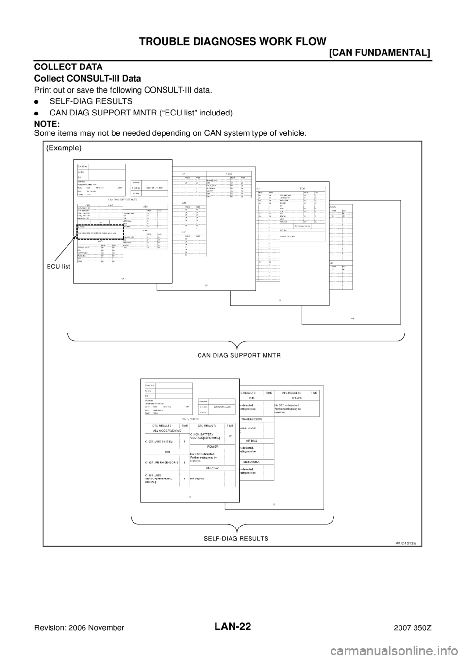
COLLECT DATA
Collect CONSULT-III Data
Print out or save the following CONSULT-III data.
�SELF-DIAG RESULTS
�CAN DIAG SUPPORT MNTR (“ECU list” included)
NOTE:
Some items may not be needed depending on CAN system type of vehicle.
PKID1212E
Page 23 of 76
TROUBLE DIAGNOSES WORK FLOW
LAN-23
[CAN FUNDAMENTAL]
C
D
E
F
G
H
I
J
L
MA
B
LAN
Revision: 2006 November2007 350Z
Create On-board Diagnosis Copy Sheet
Display the trouble diagnosis result of CAN communication with the on-board diagnosis function on the vehicle
monitor, etc. Copy them on the on-board diagnosis copy sheet.
NOTE:
For some models, CAN communication diagnosis result is received from the vehicle monitor. (CONSULT-III is
not available.)
SKIB8722E
Page 24 of 76
LAN-24
[CAN FUNDAMENTAL]
TROUBLE DIAGNOSES WORK FLOW
Revision: 2006 November2007 350Z
CREATE DIAGNOSIS SHEET
NOTE:
Be sure to use the diagnosis sheet for the correct CAN system type.
Print Diagnosis Sheet
Print the diagnosis sheet for the applicable CAN system type.
Check Collected Data
Make sure that all ECUs are received, referring to “ECU list”.
�For abbreviations, refer to LAN-41, "Abbreviation List" .
PKID1213E
Page 25 of 76
TROUBLE DIAGNOSES WORK FLOW
LAN-25
[CAN FUNDAMENTAL]
C
D
E
F
G
H
I
J
L
MA
B
LAN
Revision: 2006 November2007 350Z
DETECT THE ROOT CAUSE
Identify the root cause using the created diagnosis sheet.
Identifying the root cause
�Draw a line on the diagnosis sheet to indicate the possible cause. Narrow the search.
NOTE:
�Color-code when drawing lines.
�Do not draw a line onto a existing line.
�Drawing a line is not necessary if the circuit is shorted. Refer to LAN-32, "Present Error — Short Circuit —
" , LAN-39, "Past Error — Short Circuit —" .
Refer to the following for details of the trouble diagnosis procedure.
�LAN-26, "Present Error — Open Circuit —"
�LAN-32, "Present Error — Short Circuit —"
�LAN-33, "Past Error — Open Circuit —"
�LAN-39, "Past Error — Short Circuit —"
NOTE:
When the root cause appears to be a branch line or short circuit, be sure to check the control unit as well as
the communication line.
Page 26 of 76
LAN-26
[CAN FUNDAMENTAL]
TROUBLE DIAGNOSES WORK FLOW
Revision: 2006 November2007 350Z
Present Error — Open Circuit —
Identify the error circuit using information from the “CAN DIAG SUPPORT MNTR” (“ECU list” included).
1. ECU list: Check the items indicated in “ECU list”. Draw a line on the diagnosis sheet to indicate the error
circuit.
NOTE:
CAN communication line has no error if units other than Diag on CAN units are indicated. An error may be
on the power supply of the control unit, DDL1 line or DDL2 line.
a. “TCM” which is Diag on CAN unit, is not indicated on “ECU list”. This indicates that DLC is not receiving a
signal from TCM. Draw a line to indicate an error between DLC and TCM (line 1-a in the figure).
NOTE:
�Diag on CAN units are not indicated on the “ECU list” when the CAN line between Diag on CAN unit
and the data link connector is open.
�For a description of Diag on CAN, refer to LAN-6, "Diag on CAN" .
PKID1214E
Page 27 of 76
TROUBLE DIAGNOSES WORK FLOW
LAN-27
[CAN FUNDAMENTAL]
C
D
E
F
G
H
I
J
L
MA
B
LAN
Revision: 2006 November2007 350Z
2. CAN DIAG SUPPORT MNTR: Check each item on “CAN DIAG SUPPORT MNTR”. Draw a line on the
diagnosis sheet to indicate the error circuit.
a. Reception item of “ECM”: On “TCM”, “UNKWN” is indicated. This means ECM cannot receive the signal
from TCM. Draw a line to indicate an error between ECM and TCM (line 2-a in the figure).
NOTE:
If “UNKWN” is indicated on “TRANSMIT DIAG”, then the control unit cannot transmit CAN communication
signal to each unit. Draw a line between the control unit and the splice.
b. Reception item of “AFS”: On “TCM”, “UNKWN” is indicated. This means AFS cannot receive the signal
from TCM. Draw a line to indicate an error between AFS and TCM (line 2-b in the figure).
c. Reception item of “AV”: “UNKWN” is not indicated. This indicates normal communication between AV and
its receiving units. Do not draw any line.
PKID1215E
Page 28 of 76
LAN-28
[CAN FUNDAMENTAL]
TROUBLE DIAGNOSES WORK FLOW
Revision: 2006 November2007 350Z
d. Reception item of “BCM”: On “TCM”, “UNKWN” is indicated. This means BCM cannot receive the signal
from TCM. Draw a line to indicate an error between BCM and TCM (line 2-d in the figure).
e. Reception item of “EPS” and “I-KEY”: “UNKWN” is not indicated. This indicates normal communication
between EPS and I-KEY and their receiving units. Do not draw any line.
NOTE:
On CAN DIAG SUPPORT MNTR (without PAST), “UNKWN” is indicated even though the item is not used
in the trouble diagnosis. For the details of each item on CAN diagnostic support monitor, refer to LAN-44,
"CAN Diagnostic Support Monitor" .
PKID1216E
Page 29 of 76
TROUBLE DIAGNOSES WORK FLOW
LAN-29
[CAN FUNDAMENTAL]
C
D
E
F
G
H
I
J
L
MA
B
LAN
Revision: 2006 November2007 350Z
f. Reception item of “M&A”: On “TCM”, “UNKWN” is indicated. This means M&A cannot receive the signal
from TCM. Draw a line to indicate an error between M&A and TCM (line 2-f in the figure).
g. Reception item of “ADP”: On “TCM”, “UNKWN” is indicated. This means ADP cannot receive the signal
from TCM. Draw a line to indicate an error between ADP and TCM (line 2-g in the figure).
h. Reception item of “ABS”: “UNKWN” is not indicated. This indicates normal communication between ABS
and its receiving units. Do not draw any line.
PKID1217E
Page 30 of 76
LAN-30
[CAN FUNDAMENTAL]
TROUBLE DIAGNOSES WORK FLOW
Revision: 2006 November2007 350Z
i. Reception item of “IPDM-E”: “UNKWN” is not indicated. This indicates normal communication between
IPDM-E and its receiving units. Do not draw any line.
3. Based on information received from “CAN DIAG SUPPORT MNTR”, place a check mark on the known
good CAN communication line between ECM and IPDM-E.
a. Through the previous procedure, the circuit between ADP splice and TCM has the most amount of lines
(shade 3-a in the figure).
b. Place a check mark on the known good lines to establish the error circuit.
Reception item of “IPDM-E”: On “ECM”, “OK” is indicated. IPDM-E communicates normally with ECM. Put
a check mark on the normal circuit between ECM and IPDM-E (check mark 3-b in the figure).
PKID1218E
Trending: coolant level, headlamp, lights, fuel, wiring diagram, lock, warning
![NISSAN 350Z 2007 Z33 LAN System Owners Manual TROUBLE DIAGNOSES WORK FLOW
LAN-21
[CAN FUNDAMENTAL]
C
D
E
F
G
H
I
J
L
MA
B
LAN
Revision: 2006 November2007 350Z
CREATE INTERVIEW SHEET
Fill out the symptom described by the customer, vehicle conditio](/img/5/774/w960_774-20.png "NISSAN 350Z 2007 Z33 LAN System Owners Manual TROUBLE DIAGNOSES WORK FLOW
LAN-21
[CAN FUNDAMENTAL]
C
D
E
F
G
H
I
J
L
MA
B
LAN
Revision: 2006 November2007 350Z
CREATE INTERVIEW SHEET
Fill out the symptom described by the customer, vehicle conditio")
![NISSAN 350Z 2007 Z33 LAN System Owners Manual TROUBLE DIAGNOSES WORK FLOW
LAN-23
[CAN FUNDAMENTAL]
C
D
E
F
G
H
I
J
L
MA
B
LAN
Revision: 2006 November2007 350Z
Create On-board Diagnosis Copy Sheet
Display the trouble diagnosis result of CAN commun](/img/5/774/w960_774-22.png "NISSAN 350Z 2007 Z33 LAN System Owners Manual TROUBLE DIAGNOSES WORK FLOW
LAN-23
[CAN FUNDAMENTAL]
C
D
E
F
G
H
I
J
L
MA
B
LAN
Revision: 2006 November2007 350Z
Create On-board Diagnosis Copy Sheet
Display the trouble diagnosis result of CAN commun")
![NISSAN 350Z 2007 Z33 LAN System Owners Manual LAN-24
[CAN FUNDAMENTAL]
TROUBLE DIAGNOSES WORK FLOW
Revision: 2006 November2007 350Z
CREATE DIAGNOSIS SHEET
NOTE:
Be sure to use the diagnosis sheet for the correct CAN system type.
Print Diagnosis S](/img/5/774/w960_774-23.png "NISSAN 350Z 2007 Z33 LAN System Owners Manual LAN-24
[CAN FUNDAMENTAL]
TROUBLE DIAGNOSES WORK FLOW
Revision: 2006 November2007 350Z
CREATE DIAGNOSIS SHEET
NOTE:
Be sure to use the diagnosis sheet for the correct CAN system type.
Print Diagnosis S")
![NISSAN 350Z 2007 Z33 LAN System Owners Manual TROUBLE DIAGNOSES WORK FLOW
LAN-25
[CAN FUNDAMENTAL]
C
D
E
F
G
H
I
J
L
MA
B
LAN
Revision: 2006 November2007 350Z
DETECT THE ROOT CAUSE
Identify the root cause using the created diagnosis sheet.
Identi](/img/5/774/w960_774-24.png "NISSAN 350Z 2007 Z33 LAN System Owners Manual TROUBLE DIAGNOSES WORK FLOW
LAN-25
[CAN FUNDAMENTAL]
C
D
E
F
G
H
I
J
L
MA
B
LAN
Revision: 2006 November2007 350Z
DETECT THE ROOT CAUSE
Identify the root cause using the created diagnosis sheet.
Identi")
![NISSAN 350Z 2007 Z33 LAN System Owners Manual LAN-26
[CAN FUNDAMENTAL]
TROUBLE DIAGNOSES WORK FLOW
Revision: 2006 November2007 350Z
Present Error — Open Circuit —
Identify the error circuit using information from the “CAN DIAG SUPPORT MNTR�](/img/5/774/w960_774-25.png "NISSAN 350Z 2007 Z33 LAN System Owners Manual LAN-26
[CAN FUNDAMENTAL]
TROUBLE DIAGNOSES WORK FLOW
Revision: 2006 November2007 350Z
Present Error — Open Circuit —
Identify the error circuit using information from the “CAN DIAG SUPPORT MNTR�")
![NISSAN 350Z 2007 Z33 LAN System Owners Manual TROUBLE DIAGNOSES WORK FLOW
LAN-27
[CAN FUNDAMENTAL]
C
D
E
F
G
H
I
J
L
MA
B
LAN
Revision: 2006 November2007 350Z
2. CAN DIAG SUPPORT MNTR: Check each item on “CAN DIAG SUPPORT MNTR”. Draw a line o](/img/5/774/w960_774-26.png "NISSAN 350Z 2007 Z33 LAN System Owners Manual TROUBLE DIAGNOSES WORK FLOW
LAN-27
[CAN FUNDAMENTAL]
C
D
E
F
G
H
I
J
L
MA
B
LAN
Revision: 2006 November2007 350Z
2. CAN DIAG SUPPORT MNTR: Check each item on “CAN DIAG SUPPORT MNTR”. Draw a line o")
![NISSAN 350Z 2007 Z33 LAN System Owners Manual LAN-28
[CAN FUNDAMENTAL]
TROUBLE DIAGNOSES WORK FLOW
Revision: 2006 November2007 350Z
d. Reception item of “BCM”: On “TCM”, “UNKWN” is indicated. This means BCM cannot receive the signal
f](/img/5/774/w960_774-27.png "NISSAN 350Z 2007 Z33 LAN System Owners Manual LAN-28
[CAN FUNDAMENTAL]
TROUBLE DIAGNOSES WORK FLOW
Revision: 2006 November2007 350Z
d. Reception item of “BCM”: On “TCM”, “UNKWN” is indicated. This means BCM cannot receive the signal
f")
![NISSAN 350Z 2007 Z33 LAN System Owners Manual TROUBLE DIAGNOSES WORK FLOW
LAN-29
[CAN FUNDAMENTAL]
C
D
E
F
G
H
I
J
L
MA
B
LAN
Revision: 2006 November2007 350Z
f. Reception item of “M&A”: On “TCM”, “UNKWN” is indicated. This means M&A](/img/5/774/w960_774-28.png "NISSAN 350Z 2007 Z33 LAN System Owners Manual TROUBLE DIAGNOSES WORK FLOW
LAN-29
[CAN FUNDAMENTAL]
C
D
E
F
G
H
I
J
L
MA
B
LAN
Revision: 2006 November2007 350Z
f. Reception item of “M&A”: On “TCM”, “UNKWN” is indicated. This means M&A")
![NISSAN 350Z 2007 Z33 LAN System Owners Manual LAN-30
[CAN FUNDAMENTAL]
TROUBLE DIAGNOSES WORK FLOW
Revision: 2006 November2007 350Z
i. Reception item of “IPDM-E”: “UNKWN” is not indicated. This indicates normal communication between
IPDM-](/img/5/774/w960_774-29.png "NISSAN 350Z 2007 Z33 LAN System Owners Manual LAN-30
[CAN FUNDAMENTAL]
TROUBLE DIAGNOSES WORK FLOW
Revision: 2006 November2007 350Z
i. Reception item of “IPDM-E”: “UNKWN” is not indicated. This indicates normal communication between
IPDM-")