air condition NISSAN 370Z 2020 Owner´s Manual
[x] Cancel search | Manufacturer: NISSAN, Model Year: 2020, Model line: 370Z, Model: NISSAN 370Z 2020Pages: 455, PDF Size: 2.22 MB
Page 83 of 455
Supplemental air bag warning
light
After pushing the ignition switch to the
ON position, the supplemental air bag
warning light will illuminate. The air bag
warning light will turn off after about 7
seconds if the front air bag, side air bag
and curtain air bag systems and/or pre-
tensioner system are operational.
If any of the following conditions occur,
the front air bag, side air bag and curtain
air bag systems and/or pretensioner
system need servicing.
. The supplemental air bag warning
light remains on after approximately
7 seconds.
. The supplemental air bag warning
light flashes intermittently.
. The supplemental air bag warning
light does not come on at all.
It is recommended you visit a NISSAN
dealer for these services.
Unless checked and repaired, the Supple-
mental Restraint Systems and/or the
pretensioner seat belt may not function
properly.
For additional information, see “Supple-
mental restraint system” (P.1-31).
WARNING
If the supplemental air bag warning
light is on, it could mean that the
front air bag, side air bag and curtain
air bag systems and/or pretensioner
system will not operate in an acci-
dent. To help avoid injury to yourself
or others, have your vehicle checked.
It is recommended you visit a NISSAN
dealer for this service.
Vehicle Dynamic Control (VDC)
warning light
When the ignition switch is in the ON
position, the Vehicle Dynamic Control
(VDC) warning light illuminates and then
turns off.
The light will blink when the VDC system
or the traction control system is operat-
ing, thus alerting the driver that the
vehicle is nearing its traction limits. The
road surface may be slippery.
When the VDC warning light illuminates
when the VDC system is turned on, this
light alerts the driver to the fact that the
VDC system’s fail-safe mode is operating,
for example the VDC system may not be
functioning properly. Have the system checked. It is recommended you visit a
NISSAN dealer for this service. If a mal-
function occurs in the system, the VDC
system function will be canceled but the
vehicle is still driveable. For additional
information, see “Vehicle Dynamic Control
(VDC) system” (P.5-30) of this manual.
INDICATOR LIGHTS
Cruise indicator light
Cruise main switch indicator:
This light illuminates when the cruise
control main switch is pushed. The light
turns off when the main switch is pushed
again. When the cruise main switch in-
dicator light illuminates, the cruise control
system is operational. (See “Cruise con-
trol” (P.5-22).)
Cruise malfunction:
If the cruise indicator light blinks while the
engine is running, it may indicate the
cruise control system is not functioning
properly. Have the system checked. It is
recommended you visit a NISSAN dealer
for this service. (See “Cruise control” (P.5-
22).)
Instruments and controls2-15
Page 85 of 455
commended you visit a NISSAN dealer
for this service. You do not need to
have your vehicle towed to the dealer.
CAUTION
Continued vehicle operation without
having the emission control system
checked and repaired as necessary
could lead to poor driveability, re-
duced fuel economy, and possible
damage to the emission control sys-
tem.
Rear fog light indicator light (if
so equipped)
The rear fog light indicator light illumi-
nates when the rear fog light is on. (See
“Fog light switch” (P.2-39).)
Security indicator light
The light blinks when the ignition switch
is in the ACC, OFF or LOCK position. This
function indicates the security system
equipped on the vehicle is operational.
If the security system is malfunctioning,
this light will remain on while the ignition
switch is in the ON position. For additional
information, see “Security systems” (P.2- 30).
Soft top indicator light (Road-
ster models)
This light illuminates when the soft top is
being operated or it is stopped before
reaching a full open/close state. When the
top is fully opened or closed, the light will
turn off.
The light blinks while the soft top is not
fully opened or closed under the following
conditions:
. When the vehicle is driven.
. When the shift lever is in the R
(Reverse) position.
Be sure to fully open or close the soft top
when driving the vehicle.
The soft top can be moved with the soft
top operating switch only under all of the
following conditions:
. When the vehicle is stopped.
. When the ignition switch is ON.
. When the trunk is closed.
. When the shift lever is in a position
other than the R (Reverse) position.
CAUTION
Operate the soft top with the engine
running to prevent a discharged
battery.
When the soft top is operating, if any of
the above conditions are discontinued or
any of the following conditions are met,
the top will stop operating.
. When the shift lever is in the R
(Reverse) position.
. When the vehicle moves at a speed of
3 MPH (5 km/h) or more.
. When the battery voltage is extremely
low.
. When the temperature of the soft top
system becomes extremely high.
Release the operating switch, and push it
again under the above conditions until
the top is fully opened or closed. The soft
top indicator light will turn off when the
top operation is completely finished.
If the soft top indicator light illuminates
with the ignition switch ON, it may
indicate the electric soft top control unit
is not functioning properly. Have your
vehicle checked as soon as possible. It is
recommended you visit a NISSAN dealer
for this service.
Instruments and controls2-17
Page 107 of 455
signal will automatically flash three times.
Choose the appropriate method to signal
a lane change based on road and traffic
conditions.
SIC4066
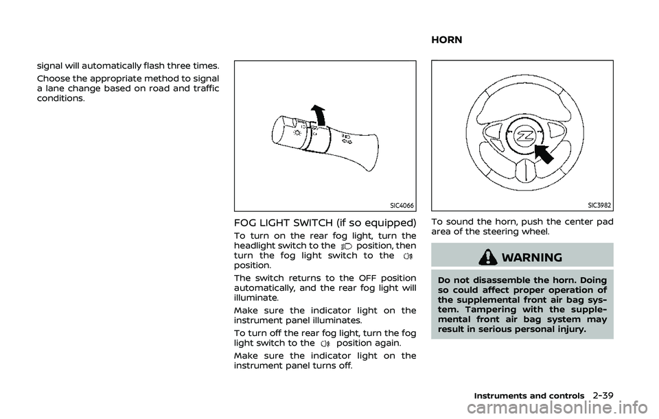
FOG LIGHT SWITCH (if so equipped)
To turn on the rear fog light, turn the
headlight switch to theposition, then
turn the fog light switch to the
position.
The switch returns to the OFF position
automatically, and the rear fog light will
illuminate.
Make sure the indicator light on the
instrument panel illuminates.
To turn off the rear fog light, turn the fog
light switch to the
position again.
Make sure the indicator light on the
instrument panel turns off.
SIC3982
To sound the horn, push the center pad
area of the steering wheel.
WARNING
Do not disassemble the horn. Doing
so could affect proper operation of
the supplemental front air bag sys-
tem. Tampering with the supple-
mental front air bag system may
result in serious personal injury.
Instruments and controls2-39
HORN
Page 110 of 455
2-42Instruments and controls
CAUTION
.Do not place objects in front of
the intake inlets located behind
and under the front seat. Doing
so could cause improper opera-
tion or interruption of the opera-
tion.
. The battery could run down if the
climate controlled seat is oper-
ated while the engine is not run-
ning.
. Do not use the climate controlled
seat for extended periods or
when no one is using the seat.
. Do not put anything on the seat
which insulates heat, such as a
blanket, cushion, seat cover, etc.
Otherwise, the seat may become
overheated.
. Do not place anything hard or
heavy on the seat or pierce it with
a pin or similar object. This may
result in damage to the climate
controlled seat.
. Any liquid spilled on the seat
should be removed immediately
with a dry cloth. .
The climate controlled seat has
air filters. Do not operate the
climate controlled seat without
the air filters. This may result in
damage to the system.
. When cleaning the seat, never use
gasoline, thinner, or any similar
materials.
. If any malfunctions are found or
the climate controlled seat does
not operate, turn the switch off
and have the system checked. It
is recommended you visit a
NISSAN dealer for this service.
SSD1161
The vehicle should be driven with the
Vehicle Dynamic Control (VDC) system on
for most driving conditions.
If the vehicle is stuck in mud or snow, the
VDC system reduces the engine output to
reduce wheel spin. The engine speed will
be reduced even if the accelerator is
depressed to the floor. If maximum en-
gine power is needed to free a stuck
vehicle, turn the VDC system off.
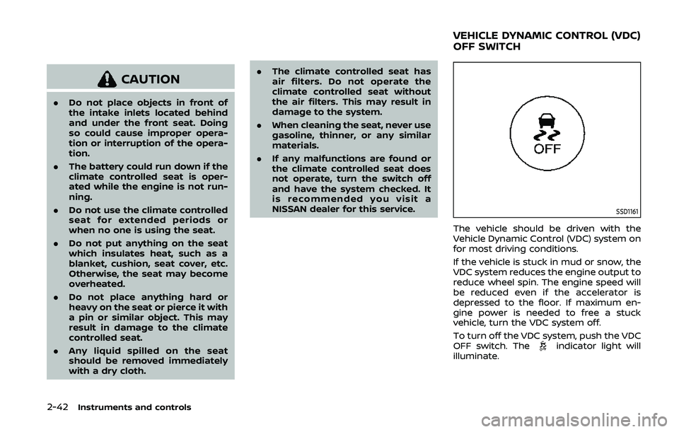
To turn off the VDC system, push the VDC
OFF switch. The
indicator light will
illuminate.
VEHICLE DYNAMIC CONTROL (VDC)
OFF SWITCH
Page 111 of 455
Push the VDC OFF switch again or restart
the engine to turn on the system. (See
“Vehicle Dynamic Control (VDC) system”
(P.5-30).)
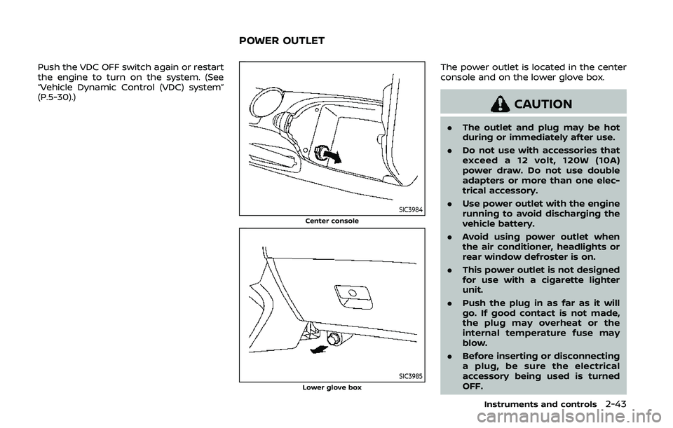
SIC3984Center console
SIC3985Lower glove box
The power outlet is located in the center
console and on the lower glove box.
CAUTION
.The outlet and plug may be hot
during or immediately after use.
. Do not use with accessories that
exceed a 12 volt, 120W (10A)
power draw. Do not use double
adapters or more than one elec-
trical accessory.
. Use power outlet with the engine
running to avoid discharging the
vehicle battery.
. Avoid using power outlet when
the air conditioner, headlights or
rear window defroster is on.
. This power outlet is not designed
for use with a cigarette lighter
unit.
. Push the plug in as far as it will
go. If good contact is not made,
the plug may overheat or the
internal temperature fuse may
blow.
. Before inserting or disconnecting
a plug, be sure the electrical
accessory being used is turned
OFF.
Instruments and controls2-43
POWER OUTLET
Page 132 of 455
3-6Pre-driving checks and adjustments
WARNING
.Radio waves could adversely af-
fect electric medical equipment.
Those who use a pacemaker
should contact the electric med-
ical equipment manufacturer for
the possible influences before
use.
. The Intelligent Key transmits
radio waves when the buttons
are pushed. The FAA advises that
the radio waves may affect air-
craft navigation and communica-
tion systems. Do not operate the
Intelligent Key while on an air-
plane. Make sure the buttons are
not operated unintentionally
when the unit is stored during a
flight.
The Intelligent Key system can operate all
the door and rear hatch/trunk lid locks
using the remote controller function or
pushing the request switch on the vehicle
without taking the key out from a pocket
or purse. The operating environment
and/or conditions may affect the Intelli-
gent Key system operation.
Be sure to read the following before using
the Intelligent Key system.
CAUTION
. Be sure to carry the Intelligent
Key with you when operating the
vehicle.
. Never leave the Intelligent Key in
the vehicle when you leave the
vehicle.
The Intelligent Key is always communi-
cating with the vehicle as it receives radio
waves. The Intelligent Key system trans-
mits weak radio waves. Environmental
conditions may interfere with the opera-
tion of the Intelligent Key system under
the following operating conditions.
. When operating near a location where
strong radio waves are transmitted,
such as a TV tower, power station and
broadcasting station.
. When in possession of wireless equip-
ment, such as a cellular telephone,
transceiver, and CB radio.
. When the Intelligent Key is in contact
with or covered by metallic materials.
. When any type of radio wave remote
control is used nearby.
. When the Intelligent Key is placed near
an electric appliance such as a perso-
nal computer. .
When the vehicle is parked near a
parking meter.
In such cases, correct the operating
conditions before using the Intelligent
Key function or use the mechanical key.
Although the life of the battery varies
depending on the operating conditions,
the battery’s life is approximately 2 years.
If the battery is discharged, replace it with
a new one.
When the Intelligent Key battery is almost
discharged, insert the Intelligent Key into
the Intelligent Key port to start the
engine. Replace the discharged battery
with a new one as soon as possible. For
more details, see “Push-button ignition
switch” (P.5-8).
Since the Intelligent Key is continuously
receiving radio waves, if the key is left
near equipment which transmits strong
radio waves, such as signals from a TV
and personal computer, the battery life
may become shorter.
For information regarding replacement of
a battery, see “Intelligent Key battery
replacement” (P.8-20).
As many as 4 Intelligent Keys can be
registered and used with one vehicle. For
information about the purchase and use
of additional Intelligent Keys, contact a
NISSAN dealer.
INTELLIGENT KEY SYSTEM
Page 139 of 455
WARNING
The Intelligent Key transmits radio
waves when the buttons are pushed.
The FAA advises that the radio waves
may affect aircraft navigation and
communication systems. Do not op-
erate the Intelligent Key while on an
airplane. Make sure the buttons are
not operated unintentionally when
the unit is stored during a flight.
It is possible to lock/unlock all doors, fuel-
filler door, activate the panic alarm and
open the windows by pushing the but-
tons on the Intelligent Key from outside
the vehicle.
Before locking the doors, make sure the
Intelligent Key is not left in the vehicle.
The LOCK/UNLOCK button on the Intelli-
gent Key can operate at a distance of
approximately 33 ft (10 m) from the
vehicle. (The effective distance depends
upon the conditions around the vehicle.)
As many as 4 Intelligent Keys can be used
with one vehicle. For information con-
cerning the purchase and use of addi-
tional Intelligent Keys, contact a NISSAN
dealer.
The lock and unlock buttons on the Intelligent Key will not operate when:
.
the distance between the Intelligent
Key and the vehicle is over 33 ft (10 m).
. the Intelligent Key battery is dis-
charged.
After locking with the remote keyless
entry function, pull the door handle to
make sure the doors are securely locked.
The LOCK/UNLOCK operating range var-
ies depending on the environment. To
securely operate the lock and unlock
buttons, approach the vehicle to about 3
ft (1 m) from the door.
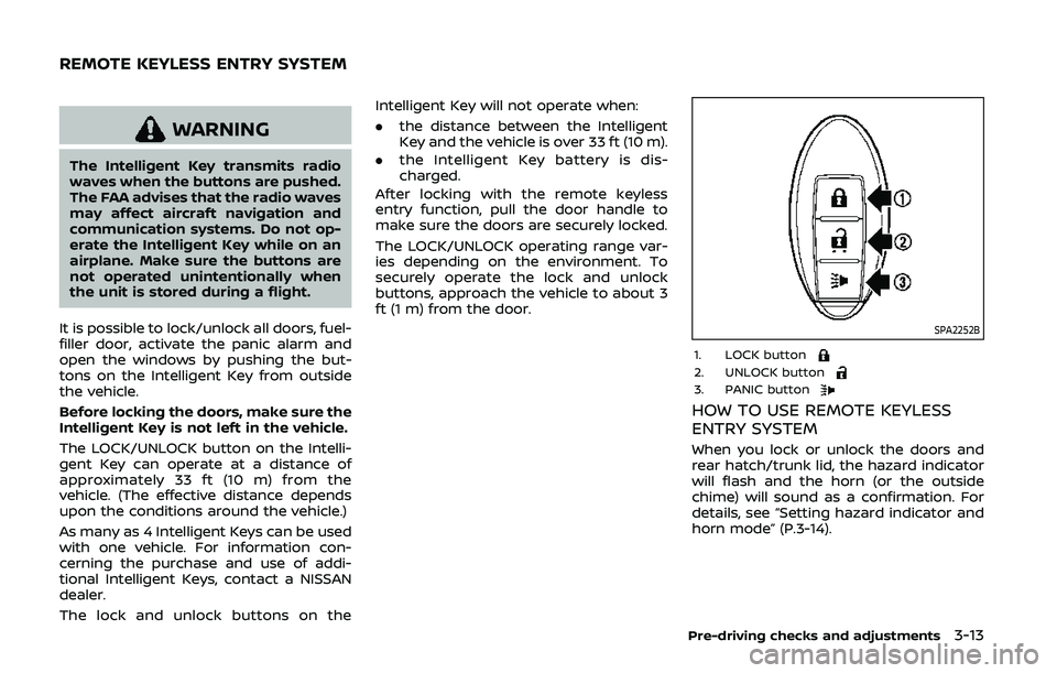
SPA2252B
1. LOCK button2. UNLOCK button3. PANIC button
HOW TO USE REMOTE KEYLESS
ENTRY SYSTEM
When you lock or unlock the doors and
rear hatch/trunk lid, the hazard indicator
will flash and the horn (or the outside
chime) will sound as a confirmation. For
details, see “Setting hazard indicator and
horn mode” (P.3-14).
Pre-driving checks and adjustments3-13
REMOTE KEYLESS ENTRY SYSTEM
Page 169 of 455
4 Center display, heater, air conditioner,audio, phone and voice recognition sys-
tems
Safety note ........................................................................\
................ 4-3
Center multi-function control panel
(models with navigation system) .................................... 4-4
How to use multi-function controller .................... 4-4
How to use touch screen ................................................ 4-5
Menu options ........................................................................\
.... 4-7
How to select menus on the screen ...................... 4-7
Vehicle information and settings (models with
navigation system) ...................................................................... 4-8 How to use STATUS button .......................................... 4-8
How to use brightness control and display
ON/OFF button ........................................................................\
4-8
How to use INFO button .................................................. 4-8
How to use SETTING button ...................................... 4-11
RearView monitor (mirror display type) .................. 4-17 RearView Monitor system operation .................. 4-18
How to read displayed lines ....................................... 4-18
Difference between predictive and
actual distances ................................................................... 4-19
Display settings (Type A) (if so equipped) ....... 4-21
Display settings (Type B) (if so equipped) ....... 4-21
RearView Monitor system limitations ................. 4-22
System maintenance ....................................................... 4-23 RearView Monitor (center display type) (if
so equipped) ........................................................................\
......... 4-24
RearView Monitor system operation ................ 4-24
How to read displayed lines .................................... 4-25
How to park with predictive course lines ...... 4-25
Difference between predictive and
actual distances ................................................................ 4-26
Adjusting the screen ...................................................... 4-28
Predictive course line settings ............................... 4-28
RearView Monitor system limitations .............. 4-29
System maintenance .................................................... 4-30
Ventilators ........................................................................\
.............. 4-30 Center ventilators ............................................................ 4-30
Side ventilators .................................................................. 4-31
Heater and air conditioner ................................................ 4-31 Automatic air conditioner (Type A) (if
so equipped) ........................................................................\
. 4-32
Automatic air conditioner (Type B) (if
so equipped) ........................................................................\
. 4-34
Operating tips ..................................................................... 4-36
In-cabin microfilter .......................................................... 4-36
Servicing air conditioner ............................................. 4-36
Page 171 of 455
WARNING
.Do not disassemble or modify
this system. If you do, it may
result in accidents, fire, or electric
shock.
. Do not use this system if you
notice any abnormality, such as
a frozen screen or lack of sound.
Continued use of the system may
result in accident, fire or electric
shock.
. In case you notice any foreign
object in the system hardware,
spill liquid on it, or notice smoke
or smell coming from it, stop
using the system immediately. It
is recommended you visit a
NISSAN dealer for servicing.
Ignoring such conditions may
lead to accidents, fire, or electric
shock.
. Park the vehicle in a safe location
and apply the parking brake to
view the images on the front
center display screen.
Do not attempt to operate the system in
extreme temperature conditions [below
−4°F (−20°C) and above 158°F (70°C)]. Operating this system under these con-
ditions may result in system malfunc-
tions.
Center display, heater, air conditioner, audio, phone and voice recognition systems4-3
SAFETY NOTE
Page 172 of 455
4-4Center display, heater, air conditioner, audio, phone and voice recognition systems
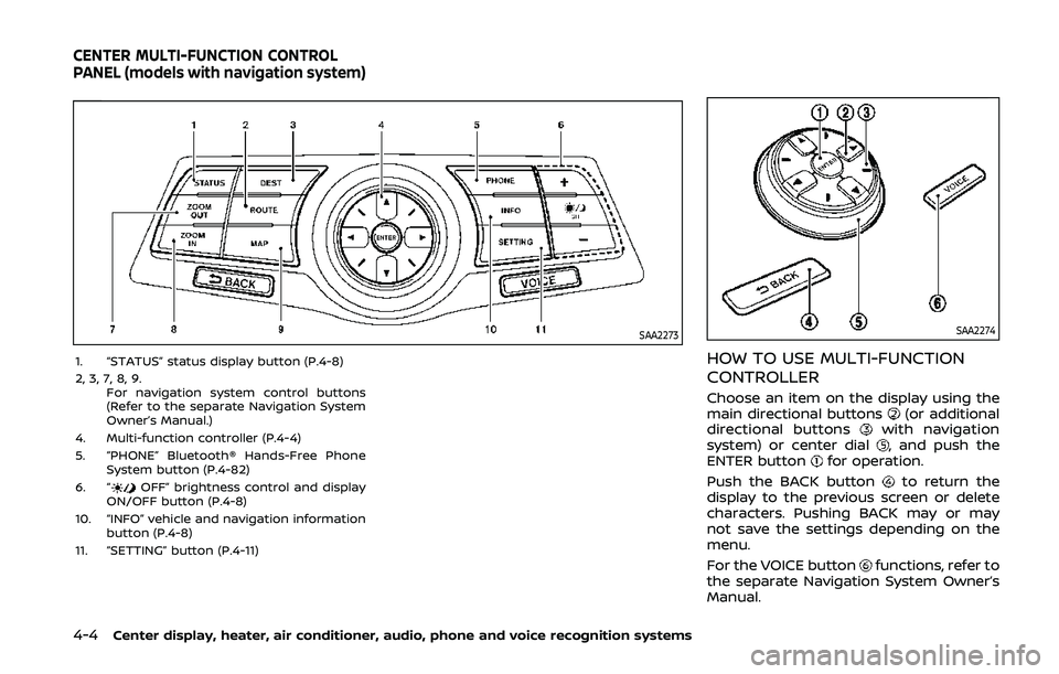
SAA2273
1. “STATUS” status display button (P.4-8)
2, 3, 7, 8, 9.For navigation system control buttons
(Refer to the separate Navigation System
Owner’s Manual.)
4. Multi-function controller (P.4-4)
5. “PHONE” Bluetooth® Hands-Free Phone System button (P.4-82)
6. “
OFF” brightness control and display
ON/OFF button (P.4-8)
10. “INFO” vehicle and navigation information button (P.4-8)
11. “SETTING” button (P.4-11)
SAA2274
HOW TO USE MULTI-FUNCTION
CONTROLLER
Choose an item on the display using the
main directional buttons(or additional
directional buttonswith navigation
system) or center dial, and push the
ENTER buttonfor operation.
Push the BACK button
to return the
display to the previous screen or delete
characters. Pushing BACK may or may
not save the settings depending on the
menu.
For the VOICE button
functions, refer to
the separate Navigation System Owner’s
Manual.
CENTER MULTI-FUNCTION CONTROL
PANEL (models with navigation system)