engine coolant NISSAN 370Z 2020 Owner´s Manual
[x] Cancel search | Manufacturer: NISSAN, Model Year: 2020, Model line: 370Z, Model: NISSAN 370Z 2020Pages: 455, PDF Size: 2.22 MB
Page 20 of 455
0-12Illustrated table of contents
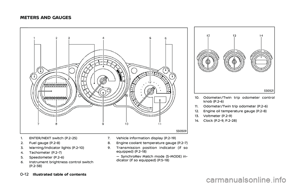
SSI0509
1. ENTER/NEXT switch (P.2-25)
2. Fuel gauge (P.2-8)
3. Warning/Indicator lights (P.2-10)
4. Tachometer (P.2-7)
5. Speedometer (P.2-6)
6. Instrument brightness control switch(P.2-38) 7. Vehicle information display (P.2-19)
8. Engine coolant temperature gauge (P.2-7)
9. Transmission position indicator (if so equipped) (P.2-18)
— SynchroRev Match mode (S-MODE) in-
dicator (if so equipped) (P.5-18)
SSI0521
10. Odometer/Twin trip odometer controlknob (P.2-6)
11. Odometer/Twin trip odometer (P.2-6)
12. Engine oil temperature gauge (P.2-8)
13. Voltmeter (P.2-9)
14. Clock (P.2-9, P.2-28)
METERS AND GAUGES
Page 21 of 455
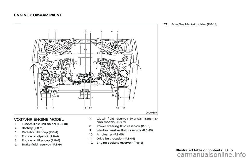
JVC0785X
VQ37VHR ENGINE MODEL1. Fuse/fusible link holder (P.8-18)
2. Battery (P.8-11)
3. Radiator filler cap (P.8-4)
4. Engine oil dipstick (P.8-6)
5. Engine oil filler cap (P.8-6)
6. Brake fluid reservoir (P.8-9)7. Clutch fluid reservoir (Manual Transmis-
sion models) (P.8-9)
8. Power steering fluid reservoir (P.8-8)
9. Window washer fluid reservoir (P.8-10)
10. Air cleaner (P.8-15)
11. Drive belt location (P.8-14)
12. Engine coolant reservoir (P.8-4) 13. Fuse/fusible link holder (P.8-18)
Illustrated table of contents0-13
ENGINE COMPARTMENT
Page 69 of 455
2 Instruments and controls
Cockpit ........................................................................\
.......................... 2-3
Instrument panel ........................................................................\
.. 2-4
Meters and gauges ..................................................................... 2-5Speedometer and odometer ........................................ 2-6
Tachometer ........................................................................\
........ 2-7
Engine coolant temperature gauge ....................... 2-7
Fuel gauge ........................................................................\
........... 2-8
Triple meter ........................................................................\
........ 2-8
Warning lights, indicator lights and
audible reminders ..................................................................... 2-10
Checking lights ..................................................................... 2-11
Warning lights ........................................................................\
2-11
Indicator lights ...................................................................... 2-15
Audible reminders .............................................................. 2-18
Vehicle information display ............................................... 2-19 Operational indicators .................................................... 2-20
Warnings and alerts .......................................................... 2-22
Maintenance indicators ................................................. 2-24
Trip computer ........................................................................\
2-25
Security systems ........................................................................\
2-30
Vehicle Security System ................................................ 2-30
NISSAN Vehicle Immobilizer System .................... 2-32
Wiper and washer switch .................................................... 2-33
Rear window defroster switch ........................................ 2-34 Headlight and turn signal switch ................................ 2-35
Xenon headlights ............................................................. 2-35
Headlight switch ............................................................... 2-36
Turn signal switch ........................................................... 2-38
Fog light switch (if so equipped) ......................... 2-39
Horn ........................................................................\
............................. 2-39
Heated seats (if so equipped) ......................................... 2-40
Climate controlled seats (if so equipped) ............. 2-41
Vehicle Dynamic Control (VDC) OFF switch ........ 2-42
Power outlet ........................................................................\
......... 2-43
Storage ........................................................................\
...................... 2-44 Instrument pocket (except for navigation
system equipped models) ......................................... 2-44
Cup holders ........................................................................\
... 2-44
Glove box ........................................................................\
........ 2-45
Console box ........................................................................\
.. 2-46
Rear parcel box .................................................................. 2-46
Cargo cover (if so equipped) ................................... 2-47
Windows ........................................................................\
................... 2-48 Power windows ................................................................. 2-48
Interior lights ........................................................................\
........ 2-51 Map lights ........................................................................\
....... 2-51
Interior light control switch ..................................... 2-51
Vanity mirror lights ................................................................. 2-52
Page 73 of 455
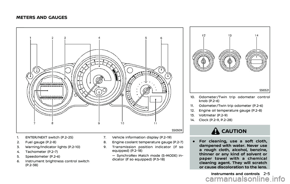
SSI0509
1. ENTER/NEXT switch (P.2-25)
2. Fuel gauge (P.2-8)
3. Warning/Indicator lights (P.2-10)
4. Tachometer (P.2-7)
5. Speedometer (P.2-6)
6. Instrument brightness control switch(P.2-38) 7. Vehicle information display (P.2-19)
8. Engine coolant temperature gauge (P.2-7)
9. Transmission position indicator (if so
equipped) (P.2-18)
— SynchroRev Match mode (S-MODE) in-
dicator (if so equipped) (P.5-18)
SSI0521
10. Odometer/Twin trip odometer controlknob (P.2-6)
11. Odometer/Twin trip odometer (P.2-6)
12. Engine oil temperature gauge (P.2-8)
13. Voltmeter (P.2-9)
14. Clock (P.2-9, P.2-28)
CAUTION
. For cleaning, use a soft cloth,
dampened with water. Never use
a rough cloth, alcohol, benzine,
thinner or any kind of solvent or
paper towel with a chemical
cleaning agent. They will scratch
or cause discoloration to the lens.
Instruments and controls2-5
METERS AND GAUGES
Page 75 of 455
SIC3974
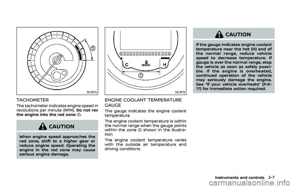
TACHOMETER
The tachometer indicates engine speed in
revolutions per minute (RPM).Do not rev
the engine into the red zone
.
CAUTION
When engine speed approaches the
red zone, shift to a higher gear or
reduce engine speed. Operating the
engine in the red zone may cause
serious engine damage.
SIC3975
ENGINE COOLANT TEMPERATURE
GAUGE
The gauge indicates the engine coolant
temperature.
The engine coolant temperature is within
the normal range when the gauge points
within the zone
shown in the illustra-
tion.
The engine coolant temperature varies
with the outside air temperature and
driving conditions.
CAUTION
If the gauge indicates engine coolant
temperature near the hot (H) end of
the normal range, reduce vehicle
speed to decrease temperature. If
gauge is over the normal range, stop
the vehicle as soon as safely possi-
ble. If the engine is overheated,
continued operation of the vehicle
may seriously damage the engine.
See “If your vehicle overheats” (P.6-
17) for immediate action required.
Instruments and controls2-7
Page 204 of 455
4-36Center display, heater, air conditioner, audio, phone and voice recognition systems
SAA2324
SAA2315
OPERATING TIPS
When the engine coolant temperature
and outside air temperature are low, the
air flow from the foot outlets may not
operate. This is not a malfunction. After
the coolant temperature warms up, air
will flow normally from the foot outlets.
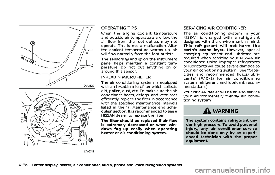
The sensors
andon the instrument
panel helps maintain a constant tem-
perature. Do not put anything on or
around this sensor.
IN-CABIN MICROFILTER
The air conditioning system is equipped
with an in-cabin microfilter which collects
dirt, pollen, dust, etc. To make sure the air
conditioner heats, defogs, and ventilates
efficiently, replace the filter in accordance
with the specified maintenance intervals
listed in the “9. Maintenance and sche-
dules” section. It is recommended to see a
NISSAN dealer to replace the filter.
The filter should be replaced if air flow
is extremely decreased or when win-
dows fog up easily when operating
heater or air conditioning system.
SERVICING AIR CONDITIONER
The air conditioning system in your
NISSAN is charged with a refrigerant
designed with the environment in mind.
This refrigerant will not harm the
earth’s ozone layer. However, special
charging equipment and lubricant are
required when servicing your NISSAN air
conditioner. Using improper refrigerants
or lubricants will cause severe damage to
your air conditioning system. (See “Capa-
cities and recommended fluids/lubri-
cants” (P.10-2) for air conditioning
system refrigerant and lubricant recom-
mendations.)
Your NISSAN dealer will be able to service
your environmentally friendly air condi-
tioning system.
WARNING
The system contains refrigerant un-
der high pressure. To avoid personal
injury, any air conditioner service
should be done only by an experi-
enced technician with the proper
equipment.
Page 299 of 455
5 Starting and driving
Precautions when starting and driving ...................... 5-2Exhaust gas (carbon monoxide) ................................ 5-2
Three-way catalyst ............................................................... 5-3
Tire Pressure Monitoring System (TPMS) ........... 5-3
Avoiding collision and rollover .................................... 5-6
Off-road recovery .................................................................. 5-6
Rapid air pressure loss ...................................................... 5-6
Drinking alcohol/drugs and driving ........................ 5-7
Push-button ignition switch ................................................ 5-8 Operating range for engine start function ....... 5-8
Push-button ignition switch operation ................ 5-9
Push-button ignition switch positions ................. 5-9
Emergency engine shut off ........................................ 5-10
Intelligent Key battery discharge ........................... 5-10
Before starting the engine ................................................. 5-11
Starting the engine .................................................................. 5-11
Driving the vehicle .................................................................... 5-12 Automatic transmission ................................................ 5-12
Manual Transmission ....................................................... 5-17
Parking brake ........................................................................\
....... 5-21
Cruise control ........................................................................\
....... 5-22 Precautions on cruise control .................................. 5-22
Cruise control operations ............................................ 5-23
Break-in schedule ..................................................................... 5-24
Fuel efficient driving tips ..................................................... 5-24 Increasing fuel economy .................................................... 5-25
Parking/parking on hills ...................................................... 5-26
Power steering ........................................................................\
.... 5-27
Brake system ........................................................................\
....... 5-27
Braking precautions ....................................................... 5-27
Parking brake break-in ................................................ 5-28
Brake assist ........................................................................\
........... 5-28 Brake assist ........................................................................\
... 5-28
Anti-lock Braking System (ABS) ............................ 5-28
Vehicle Dynamic Control (VDC) system .................. 5-30
Performance dampers (NISMO models) ................. 5-32
Cold weather driving ............................................................. 5-33 Freeing a frozen door lock ....................................... 5-33
Antifreeze ........................................................................\
........ 5-33
Battery ........................................................................\
............... 5-33
Draining of coolant water ......................................... 5-33
Tire equipment ................................................................... 5-33
Special winter equipment ......................................... 5-33
Driving on snow or ice ................................................. 5-33
Engine block heater (if so equipped) ............... 5-34
Active noise cancellation/Active sound
enhancement (if so equipped) ....................................... 5-35 Active noise cancellation ........................................... 5-35
Active sound enhancement ..................................... 5-35
Page 309 of 455
.Make sure the area around the vehicle
is clear.
. Check fluid levels such as engine oil,
coolant, brake fluid and window
washer fluid as frequently as possible,
or at least whenever you refuel.
. Check that all windows and lights are
clean.
. Visually inspect tires for their appear-
ance and condition. Also check tires
for proper inflation.
. Lock all doors.
. Position seat and adjust head re-
straints.
. Adjust inside and outside mirrors.
. Fasten seat belts and ask all passen-
gers to do likewise.
. Check the operation of warning lights
when the ignition switch is pushed to
the ON position. (See “Warning lights,
indicator lights and audible remin-
ders” (P.2-10).) 1. Apply the parking brake.
2.
Automatic Transmission (AT) model:
Move the shift lever to the P (Park) or N
(Neutral) position. (P is recommended.)
The starter is designed not to operate
unless the shift lever is in either of the
above positions.
Manual Transmission (MT) model:
Move the shift lever to the N (Neutral)
position. Depress the clutch pedal fully
to the floor.
The starter is designed not to operate
unless the clutch pedal is fully de-
pressed.
The Intelligent Key must be carried
when operating the ignition switch.
3. Push the ignition switch to the ON position. Firmly depress the brake
pedal (AT model) or the clutch pedal
(MT model) and push the ignition
switch to start the engine.
To start the engine immediately, push
and release the ignition switch while
depressing the brake pedal or the
clutch pedal with the ignition switch
in any position.
.If the engine is very hard to start inextremely cold weather or when
restarting, depress the accelerator
pedal a little (approximately 1/3 to the floor) and while holding, crank
the engine. Release the accelerator
pedal when the engine starts.
.If the engine is very hard to start
because it is flooded, depress the
accelerator pedal all the way to the
floor and hold it. Push the ignition
switch to the ON position to start
cranking the engine. After 5 or 6
seconds, stop cranking by pushing
the ignition switch to OFF. After
cranking the engine, release the
accelerator pedal. Crank the engine
with your foot off the accelerator
pedal by depressing the brake
pedal and pushing the push-button
ignition switch to start the engine.
If the engine starts, but fails to run,
repeat the above procedure.
CAUTION
Do not operate the starter for more
than 15 seconds at a time. If the
engine does not start, push the
ignition switch to OFF and wait 10
seconds before cranking again,
otherwise the starter could be da-
maged.
Starting and driving5-11
BEFORE STARTING THE ENGINE STARTING THE ENGINE
Page 316 of 455
5-18Starting and driving
SSD0536
Shifting
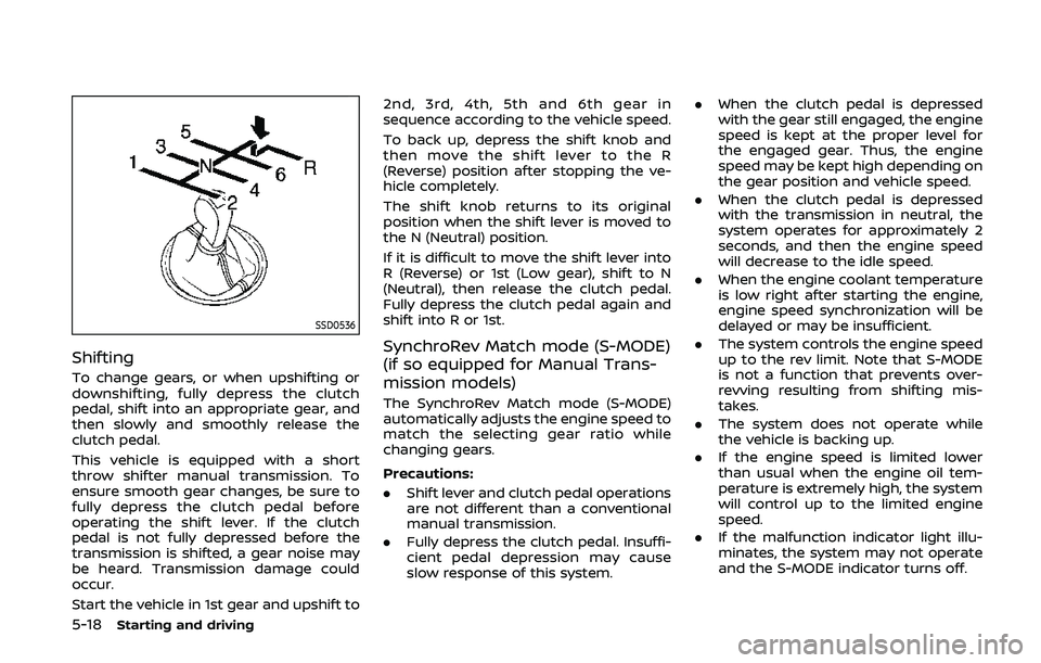
To change gears, or when upshifting or
downshifting, fully depress the clutch
pedal, shift into an appropriate gear, and
then slowly and smoothly release the
clutch pedal.
This vehicle is equipped with a short
throw shifter manual transmission. To
ensure smooth gear changes, be sure to
fully depress the clutch pedal before
operating the shift lever. If the clutch
pedal is not fully depressed before the
transmission is shifted, a gear noise may
be heard. Transmission damage could
occur.
Start the vehicle in 1st gear and upshift to2nd, 3rd, 4th, 5th and 6th gear in
sequence according to the vehicle speed.
To back up, depress the shift knob and
then move the shift lever to the R
(Reverse) position after stopping the ve-
hicle completely.
The shift knob returns to its original
position when the shift lever is moved to
the N (Neutral) position.
If it is difficult to move the shift lever into
R (Reverse) or 1st (Low gear), shift to N
(Neutral), then release the clutch pedal.
Fully depress the clutch pedal again and
shift into R or 1st.
SynchroRev Match mode (S-MODE)
(if so equipped for Manual Trans-
mission models)
The SynchroRev Match mode (S-MODE)
automatically adjusts the engine speed to
match the selecting gear ratio while
changing gears.
Precautions:
.
Shift lever and clutch pedal operations
are not different than a conventional
manual transmission.
. Fully depress the clutch pedal. Insuffi-
cient pedal depression may cause
slow response of this system. .
When the clutch pedal is depressed
with the gear still engaged, the engine
speed is kept at the proper level for
the engaged gear. Thus, the engine
speed may be kept high depending on
the gear position and vehicle speed.
. When the clutch pedal is depressed
with the transmission in neutral, the
system operates for approximately 2
seconds, and then the engine speed
will decrease to the idle speed.
. When the engine coolant temperature
is low right after starting the engine,
engine speed synchronization will be
delayed or may be insufficient.
. The system controls the engine speed
up to the rev limit. Note that S-MODE
is not a function that prevents over-
revving resulting from shifting mis-
takes.
. The system does not operate while
the vehicle is backing up.
. If the engine speed is limited lower
than usual when the engine oil tem-
perature is extremely high, the system
will control up to the limited engine
speed.
. If the malfunction indicator light illu-
minates, the system may not operate
and the S-MODE indicator turns off.
Page 320 of 455
5-22Starting and driving
SPA2110
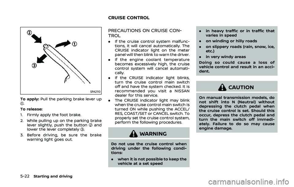
To apply:Pull the parking brake lever up.
To release:
1. Firmly apply the foot brake.
2. While pulling up on the parking brake lever slightly, push the button
and
lower the lever completely.
3. Before driving, be sure the brake warning light goes out.
PRECAUTIONS ON CRUISE CON-
TROL
.If the cruise control system malfunc-
tions, it will cancel automatically. The
CRUISE indicator light on the meter
panel will then blink to warn the driver.
. If the engine coolant temperature
becomes excessively high, the cruise
control system will cancel automati-
cally.
. If the CRUISE indicator light blinks,
turn the cruise control main switch
off and have the system checked. It is
recommended you visit a NISSAN
dealer for this service.
. The CRUISE indicator light may blink
when the cruise control main switch is
turned ON while pushing the ACCEL/
RES, COAST/SET or CANCEL switch. To
properly set the cruise control system,
perform the following procedures.
WARNING
Do not use the cruise control when
driving under the following condi-
tions:
.when it is not possible to keep the
vehicle at a set speed .
in heavy traffic or in traffic that
varies in speed
. on winding or hilly roads
. on slippery roads (rain, snow, ice,
etc.)
. in very windy areas
Doing so could cause a loss of
vehicle control and result in an acci-
dent.
CAUTION
On manual transmission models, do
not shift into N (Neutral) without
depressing the clutch pedal when
the cruise control is set. Should this
occur, depress the clutch pedal and
turn the main switch off immedi-
ately. Failure to do so may cause
engine damage.
CRUISE CONTROL