oil change NISSAN ALMERA 2001 User Guide
[x] Cancel search | Manufacturer: NISSAN, Model Year: 2001, Model line: ALMERA, Model: NISSAN ALMERA 2001Pages: 2898, PDF Size: 60.76 MB
Page 1215 of 2898
DescriptionNJEC1746SYSTEM DESCRIPTIONNJEC1746S01
Sensor Input Signal to ECMECM func-
tionActuator
Crankshaft position sensor (POS) Engine speed
EGR vol-
ume controlEGR volume control valve Camshaft position sensor (PHASE) Engine speed and cylinder number
Mass air flow sensor Amount of intake air
Engine coolant temperature sensor Engine coolant temperature
Ignition switch Start signal
Throttle position sensor Throttle position
Vehicle speed sensor Vehicle speed
Battery Battery voltage
Air conditioner switch Air conditioner operation
Power steering oil pressure switch Power steering load signal
Electrical load Electrical load signal
PNP switch Park/Neutral position signal
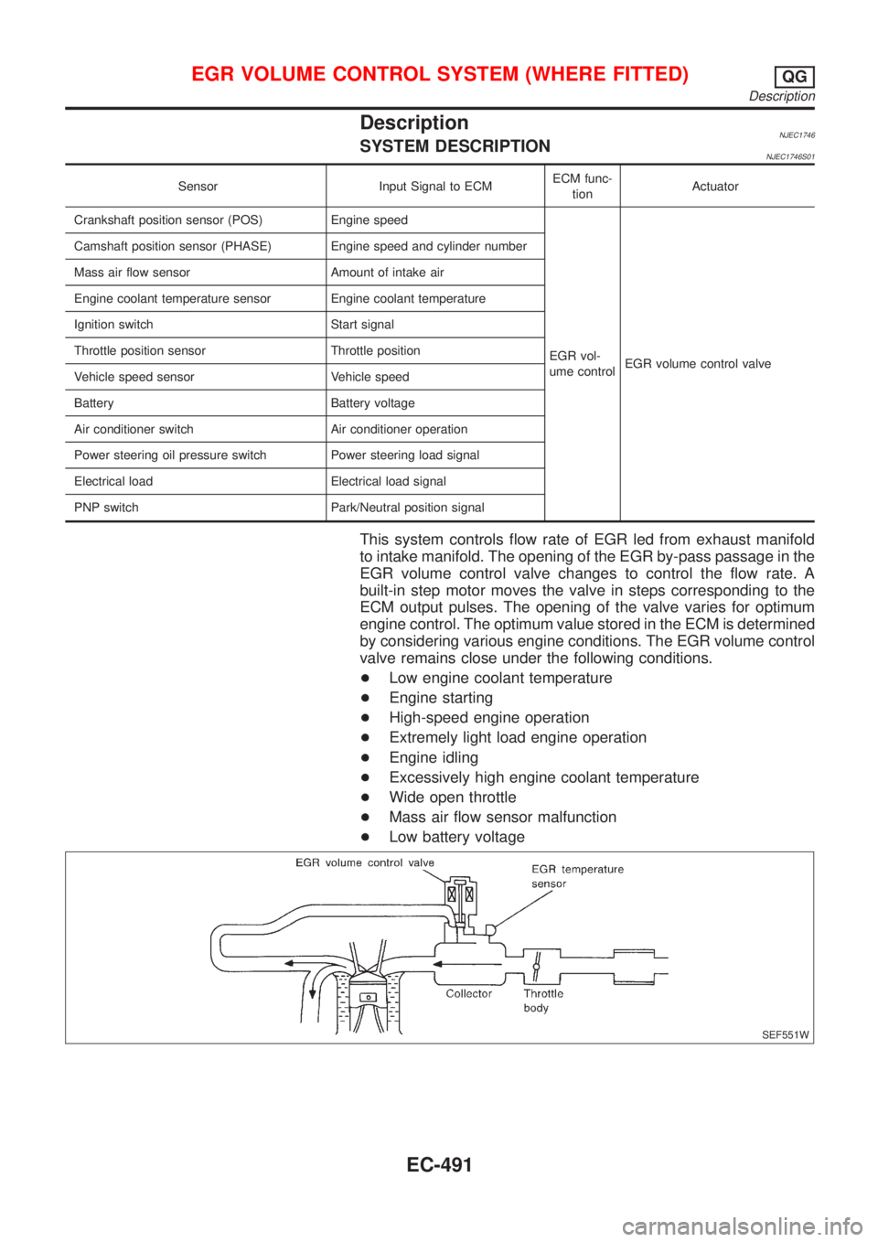
This system controls flow rate of EGR led from exhaust manifold
to intake manifold. The opening of the EGR by-pass passage in the
EGR volume control valve changes to control the flow rate. A
built-in step motor moves the valve in steps corresponding to the
ECM output pulses. The opening of the valve varies for optimum
engine control. The optimum value stored in the ECM is determined
by considering various engine conditions. The EGR volume control
valve remains close under the following conditions.
+Low engine coolant temperature
+Engine starting
+High-speed engine operation
+Extremely light load engine operation
+Engine idling
+Excessively high engine coolant temperature
+Wide open throttle
+Mass air flow sensor malfunction
+Low battery voltage
SEF551W
EGR VOLUME CONTROL SYSTEM (WHERE FITTED)QG
Description
EC-491
Page 1235 of 2898
DescriptionNJEC1758SYSTEM DESCRIPTIONNJEC1758S01
Sensor Input Signal to ECMECM func-
tionActuator
Crankshaft position sensor (POS) Engine speed
Idle air
controlIACV-AAC valve Camshaft position sensor (PHASE) Engine speed and cylinder number
Engine coolant temperature sensor Engine coolant temperature
Ignition switch Start signal
Throttle position sensor Throttle position
PNP switch Park/Neutral position
Air conditioner switch Air conditioner operation
Power steering oil pressure switch Power steering load signal
Battery Battery voltage
Vehicle speed sensor Vehicle speed
Cooling fan Cooling fan operation
Electrical load Electrical load signal
This system automatically controls engine idle speed to a specified
level. Idle speed is controlled through fine adjustment of the
amount of air which by-passes the throttle valve via IACV-AAC
valve. The IACV-AAC valve changes the opening of the air by-pass
passage to control the amount of auxiliary air. This valve is actu-
ated by a step motor built into the valve, which moves the valve in
the axial direction in steps corresponding to the ECM output sig-
nals. One step of IACV-AAC valve movement causes the respec-
tive opening of the air by-pass passage. (i.e. when the step
advances, the opening is enlarged.) The opening of the valve is
varied to allow for optimum control of the engine idling speed. The
crankshaft position sensor (POS) detects the actual engine speed
and sends a signal to the ECM. The ECM then controls the step
position of the IACV-AAC valve so that engine speed coincides with
the target value memorized in ECM. The target engine speed is the
lowest speed at which the engine can operate steadily. The opti-
mum value stored in the ECM is determined by taking into consid-
eration various engine conditions, such as during warm up,
deceleration, and engine load (air conditioner, power steering, cool-
ing fan operation and electrical load).
SEF937W
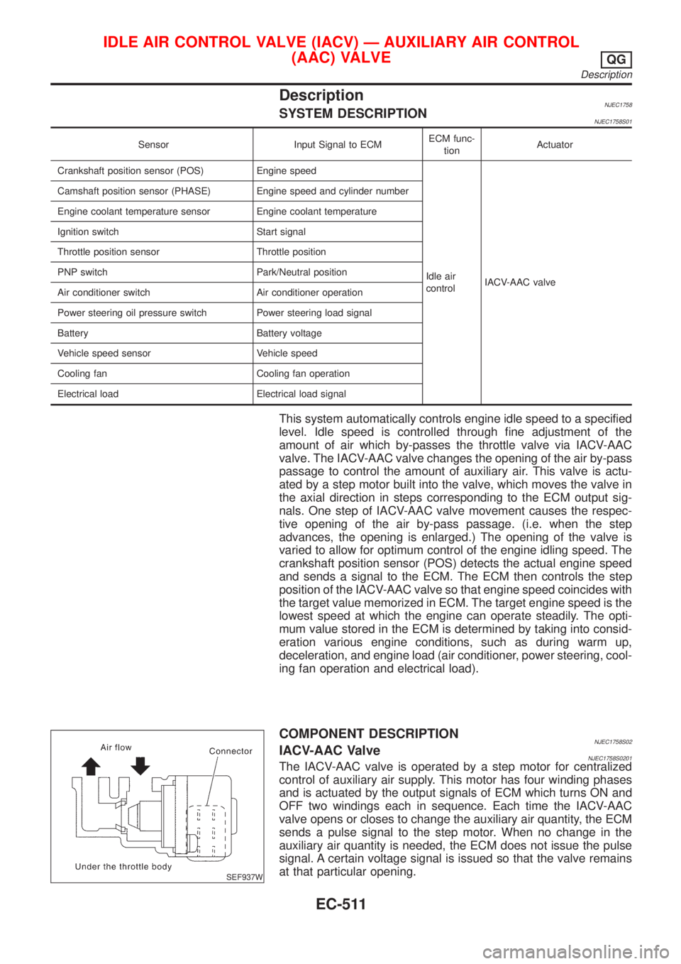
COMPONENT DESCRIPTIONNJEC1758S02IACV-AAC ValveNJEC1758S0201The IACV-AAC valve is operated by a step motor for centralized
control of auxiliary air supply. This motor has four winding phases
and is actuated by the output signals of ECM which turns ON and
OFF two windings each in sequence. Each time the IACV-AAC
valve opens or closes to change the auxiliary air quantity, the ECM
sends a pulse signal to the step motor. When no change in the
auxiliary air quantity is needed, the ECM does not issue the pulse
signal. A certain voltage signal is issued so that the valve remains
at that particular opening.
IDLE AIR CONTROL VALVE (IACV) Ð AUXILIARY AIR CONTROL
(AAC) VALVE
QG
Description
EC-511
Page 1838 of 2898

Trouble DiagnosesNJEL0385AUDIO UNITNJEL0385S05
Symptom Possible causes Repair order
Audio unit inoperative (no
digital display and no
sound from speakers).1. 10A fuse
2. Poor audio unit case ground
3. Audio unit1. Check 10A fuse [No. 1, located in fuse block (J/B)].
Turn ignition switch ON and verify that battery posi-
tive voltage is present at terminal 3 of audio unit.
2. Check audio unit case ground.
3. Remove audio unit for repair.
Audio unit presets are lost
when ignition switch is
turned OFF.1. 15A fuse
2. Audio unit1. Check 15A fuse [No. 32, located in fuse block (J/B)]
and verify that battery positive voltage is present at
terminal 9 of audio unit.
2. Remove audio unit for repair.
Individual rear speaker is
noisy or inoperative.1. Each speaker
2. Output circuit to each speaker1. Check speaker.
2. Check the output circuits to each speaker
+between audio unit and speaker amp.
+between speaker amp. and each speaker.
AM/FM stations are weak
or noisy.1. Roof antenna
2. Audio unit ground
3. Audio unit1. Check roof antenna.
2. Check audio unit ground condition.
3. Remove audio unit for repair.
Audio unit generates noise
in AM and FM modes with
engine running.1. Poor audio unit ground
2. Loose or missing ground bonding straps
3. Ignition condenser or rear window defog-
ger noise suppressor condenser
4. Ignition coil or secondary wiring
5. Audio unit1. Check audio unit ground.
2. Check ground bonding straps.
3. Replace ignition condenser or rear window defogger
noise suppressor condenser.
4. Check ignition coil and secondary wiring.
5. Remove audio unit for repair.
Audio unit generates noise
in AM and FM modes with
accessories on (switch
pops and motor noise).1. Poor audio unit ground
2. Antenna
3. Accessory ground
4. Faulty accessory1. Check audio unit ground.
2. Check antenna.
3. Check accessory ground.
4. Replace accessory.
CD AUTOCHANGERNJEL0385S06Testing Magazines and DiscsNJEL0385S06011. Confirm discs are installed correctly into the magazine (not upside down).
2. Visually inspect/compare the customer's discs with each other and other discs.
Identify any of the following conditions:
+Discs with a large outside diameter. [Normal size is 120 mm (4.72 in).]
+Discs with rough or lipped edges.
+Discs with excessive thickness [Normal size is 1.2 mm (0.047 in).]
+Discs with scratches, abrasions, or pits on the surface.
+Discs with grease/oil, fingerprints, foreign material.
+Discs are warped due to excessive heat exposure.
3. Slide/place the discs in and out of the various magazine positions.
Identify any discs and/or positions that require additional force for placement/ejection. If interference
(sticking, excessive tensions) is found, replace the magazine or the discs.
NOTE:
+Discs which are marginally out of specification (ex. dirty, scratched and so on) may play correctly
on a home stereo.
However, when used in the automotive environment skipping may occur due to the added vehicle
movement and/or vibration due to road conditions. Autochangers should not be replaced when
discs are at fault.
+Use a soft damp cloth to wipe the discs starting from the center outward in radial direction. Never
use chemical cleaning solutions to clean the discs.
AUDIO
Trouble Diagnoses
EL-280
Page 2411 of 2898
HFC-134a (R-134a) Service Tools and
Equipment
=NJHA0120Never mix HFC-134a refrigerant and/or its specified lubricant with CFC-12 (R-12) refrigerant and/or its lubri-
cant.
Separate and non-interchangeable service equipment must be used for handling each type of refrigerant/
lubricant.
Refrigerant container fittings, service hose fittings and service equipment fittings (equipment which handles
refrigerant and/or lubricant) are different between CFC-12 (R-12) and HFC-134a (R-134a). This is to avoid
mixed use of the refrigerants/lubricant.
Adapters that convert one size fitting to another must never be used: refrigerant/lubricant contamination will
occur and compressor failure will result.
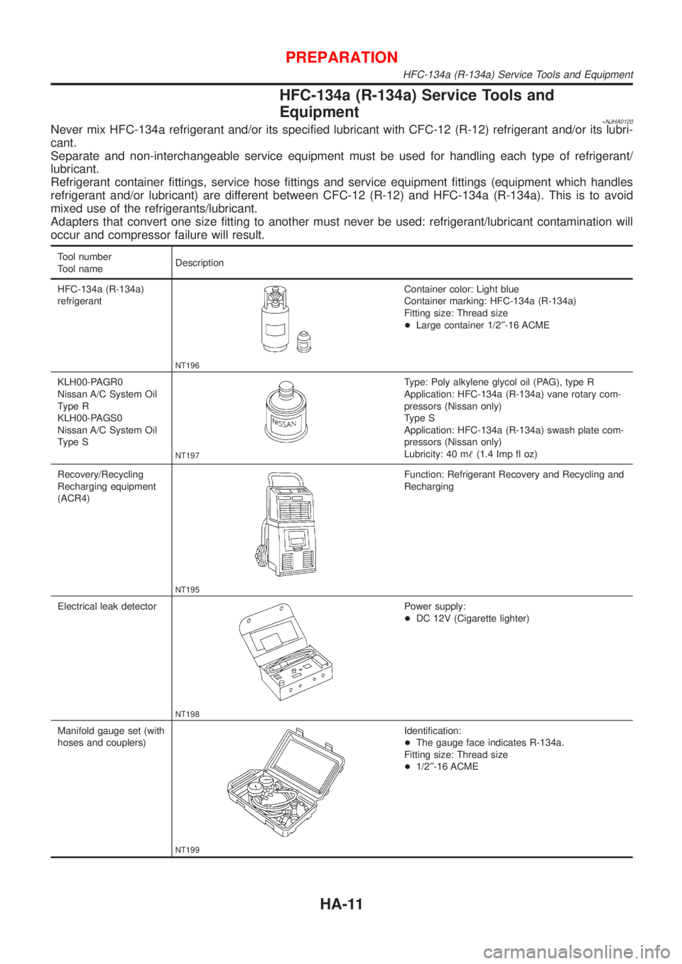
Tool number
Tool nameDescription
HFC-134a (R-134a)
refrigerant
NT196
Container color: Light blue
Container marking: HFC-134a (R-134a)
Fitting size: Thread size
+Large container 1/2²-16 ACME
KLH00-PAGR0
Nissan A/C System Oil
Type R
KLH00-PAGS0
Nissan A/C System Oil
Type S
NT197
Type: Poly alkylene glycol oil (PAG), type R
Application: HFC-134a (R-134a) vane rotary com-
pressors (Nissan only)
Type S
Application: HFC-134a (R-134a) swash plate com-
pressors (Nissan only)
Lubricity: 40 m!(1.4 Imp fl oz)
Recovery/Recycling
Recharging equipment
(ACR4)
NT195
Function: Refrigerant Recovery and Recycling and
Recharging
Electrical leak detector
NT198
Power supply:
+DC 12V (Cigarette lighter)
Manifold gauge set (with
hoses and couplers)
NT199
Identification:
+The gauge face indicates R-134a.
Fitting size: Thread size
+1/2²-16 ACME
PREPARATION
HFC-134a (R-134a) Service Tools and Equipment
HA-11
Page 2480 of 2898
Maintenance of Lubricant Quantity in
Compressor
NJHA0160The lubricant in the compressor circulates through the system with
the refrigerant. Add lubricant to compressor when replacing any
component or after a large gas leakage occurred. It is important to
maintain the specified amount.
If lubricant quantity is not maintained properly, the following mal-
functions may result:
+Lack of lubricant: May lead to a seized compressor
+Excessive lubricant: Inadequate cooling (thermal exchange
interference)
LUBRICANTNJHA0160S01Name: Nissan A/C System Oil Type R for DKV-11G compres-
sor
Part number: KLH00-PAGR0
Name: Nissan A/C System Oil Type S for CSV613 compressor
Part number: KLH00-PAGS0
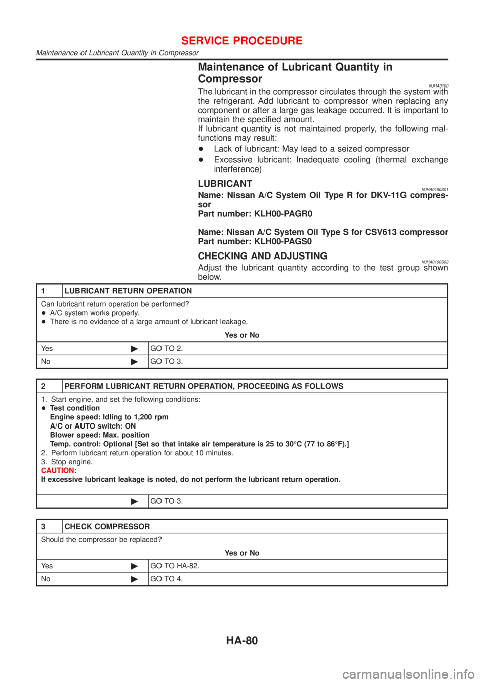
CHECKING AND ADJUSTINGNJHA0160S02Adjust the lubricant quantity according to the test group shown
below.
1 LUBRICANT RETURN OPERATION
Can lubricant return operation be performed?
+A/C system works properly.
+There is no evidence of a large amount of lubricant leakage.
YesorNo
Ye s©GO TO 2.
No©GO TO 3.
2 PERFORM LUBRICANT RETURN OPERATION, PROCEEDING AS FOLLOWS
1. Start engine, and set the following conditions:
+Test condition
Engine speed: Idling to 1,200 rpm
A/C or AUTO switch: ON
Blower speed: Max. position
Temp. control: Optional [Set so that intake air temperature is 25 to 30ÉC (77 to 86ÉF).]
2. Perform lubricant return operation for about 10 minutes.
3. Stop engine.
CAUTION:
If excessive lubricant leakage is noted, do not perform the lubricant return operation.
©GO TO 3.
3 CHECK COMPRESSOR
Should the compressor be replaced?
YesorNo
Ye s©GO TO HA-82.
No©GO TO 4.
SERVICE PROCEDURE
Maintenance of Lubricant Quantity in Compressor
HA-80
Page 2500 of 2898

A
A/C HFC134a (R134a) system precaution . HA-2
A/C HFC134a (R134a) system service
procedure .............................................. HA-78
A/C HFC134a (R134a) system service
tools ....................................................... HA-11
A/C HFC134a system service equip-
ment precaution ....................................... HA-6
A/C air flow ............................................... HA-20
A/C component layout .............................. HA-18
A/C compressor clutch removal and
installation .............................................. HA-83
A/C compressor precaution ........................ HA-5
A/C compressor special service tool .......... HA-9
A/C control linkage adjustment
(manual A/C) ......................................... HA-41
A/C control operation (manual A/C) .......... HA-19
A/C diagnostic work flow
(manual A/C) ........................................ HA-33
A/C harness layout (manual A/C) ............. HA-22
A/C lubricant (R134a) ............................... HA-80
A/C operational check ............................... HA-34
A/C performance chart .............................. HA-71
A/C performance test diagnoses .............. HA-69
A/C relay ................................................... HA-66
A/C service data specification .................. HA-97
A/C switch ................................................. HA-67
A/C, M - Wiring diagram ........................... HA-27
A/CCUT - Wiring diagram ....................... EC-830
A/T - Wiring diagram - AT - 1ST .............. AT-207
A/T - Wiring diagram - AT - 2ND ............. AT-214
A/T - Wiring diagram - AT - 3RD ............. AT-220
A/T - Wiring diagram - AT - 4TH .............. AT-227
A/T - Wiring diagram - AT - BA/FTS ....... AT-167,
276
A/T - Wiring diagram - AT - ENG SS ...... AT-173,
201
A/T - Wiring diagram - AT - FTS .............. AT-191
A/T - Wiring diagram - AT - LPSV ... AT-178, 241
A/T - Wiring diagram - AT - MAIN ........... AT-123
A/T - Wiring diagram - AT -
NONDTC .............................................. AT-292
A/T - Wiring diagram - AT -
OVRCSV ...................................... AT-155, 270
A/T - Wiring diagram - AT - PNP/SW ...... AT-185
A/T - Wiring diagram - AT - SSV/A .. AT-144, 248
A/T - Wiring diagram - AT - SSV/B .. AT-150, 254
A/T - Wiring diagram - AT - TCV ..... AT-161, 235
A/T - Wiring diagram - AT - TPS ..... AT-136, 261
A/T - Wiring diagram - AT - VSS/AT ....... AT-128,
197
A/T - Wiring diagram - AT -
VSSMTR ...................................... AT-132, 283
A/T IND - Wiring diagram ........................ EL-195
A/T control ............................................... EC-532
A/T diagnosis communication line .......... EC-434
A/T fluid temperature sensor ................... AT-194A/T shift lock system - Wiring
diagram ................................................ AT-344
A/T shift lock system ................................ AT-343
A/T trouble diagnoses .......................... AT-69, 74
AAC/V - Wiring diagram ................. EC-378, 513
ABS (anti-lock brake system) ................... BR-49
ABS - Wiring diagram ............................... BR-54
ABS sensor rotor ....................................... AX-24
APS - Wiring diagram ............................. EC-685
ATDIAG - Wiring diagram ............... EC-435, 533
Accelerator control system .................... FE-3, 19
Accelerator position sensor .................... EC-685
Air bag disposal ........................................ RS-40
Air bag precautions ...................................... GI-3
Air bag ....................................................... RS-20
Air bleeding (hydraulic clutch) ................... CL-10
Air bleeding for brake system ..................... BR-9
Air conditioner cut control ................. EC-35, 612
Air flow meter - See Mass air flow
sensor .......................................... EC-187, 673
Air mix door control linkage
adjustment ............................................. HA-43
Air spoiler, rear .......................................... BT-47
Alternator ................................................... SC-31
Angular tightening application .............. EM-4, 77
Antenna - See Power antenna ................ EL-282
Anti-lock brake system - Wiring
diagram .................................................. BR-54
Audio and A/C control removal and
installation - See Instrument panel ........ BT-25
Audio ........................................................ EL-258
Automatic transaxle number ...................... GI-41
Auxiliary air control (AAC) valve ..... EC-376, 511
B
Back-up lamp switch (M/T) ....................... MT-21
Back-up lamp ............................................. EL-87
Ball joint (front) .......................................... SU-13
Basic inspection ...................... EC-100, 128, 641
Battery ......................................................... SC-3
Baulk ring (M/T) ............................ MT-31, 55, 93
Blower motor ............................................. HA-54
Blower resistor .......................................... HA-54
Board-on lift ................................................ GI-44
Body alignment .......................................... BT-77
Brake booster ............................................ BR-20
Brake fluid change ...................................... BR-8
Brake fluid level and line check .................. BR-8
Brake hydraulic line .................................. BR-10
Brake master cylinder ............................... BR-14
Brake pedal ............................................... BR-12
Bulb specifications ................................... EL-574
Bumper, front .............................................. BT-7
Bumper, rear .............................................. BT-10
ALPHABETICAL INDEX
IDX-2
Page 2514 of 2898
SLC986AA
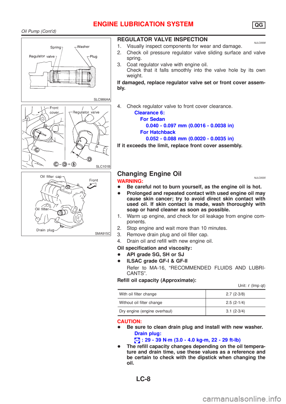
REGULATOR VALVE INSPECTIONNJLC00081. Visually inspect components for wear and damage.
2. Check oil pressure regulator valve sliding surface and valve
spring.
3. Coat regulator valve with engine oil.
Check that it falls smoothly into the valve hole by its own
weight.
If damaged, replace regulator valve set or front cover assem-
bly.
SLC101B
4. Check regulator valve to front cover clearance.
Clearance 6:
For Sedan
0.040 - 0.097 mm (0.0016 - 0.0038 in)
For Hatchback
0.052 - 0.088 mm (0.0020 - 0.0035 in)
If it exceeds the limit, replace front cover assembly.
SMA915C
Changing Engine OilNJLC0035WARNING:
+Be careful not to burn yourself, as the engine oil is hot.
+Prolonged and repeated contact with used engine oil may
cause skin cancer; try to avoid direct skin contact with
used oil. If skin contact is made, wash thoroughly with
soap or hand cleaner as soon as possible.
1. Warm up engine, and check for oil leakage from engine com-
ponents.
2. Stop engine and wait more than 10 minutes.
3. Remove drain plug and oil filler cap.
4. Drain oil and refill with new engine oil.
Oil specification and viscosity:
+API grade SG, SH or SJ
+ILSAC grade GF-I & GF-II
Refer to MA-16, ªRECOMMENDED FLUIDS AND LUBRI-
CANTSº.
Refill oil capacity (Approximate):
Unit:!(Imp qt)
With oil filter change 2.7 (2-3/8)
Without oil filter change 2.5 (2-1/4)
Dry engine (engine overhaul) 3.1 (2-3/4)
CAUTION:
+Be sure to clean drain plug and install with new washer.
Drain plug:
: 29 - 39 N´m (3.0 - 4.0 kg-m, 22 - 29 ft-lb)
+The refill capacity changes depending on the oil tempera-
ture and drain time, use these values as a reference and
be certain to check with the dipstick when changing the
oil.
ENGINE LUBRICATION SYSTEMQG
Oil Pump (Cont'd)
LC-8
Page 2516 of 2898
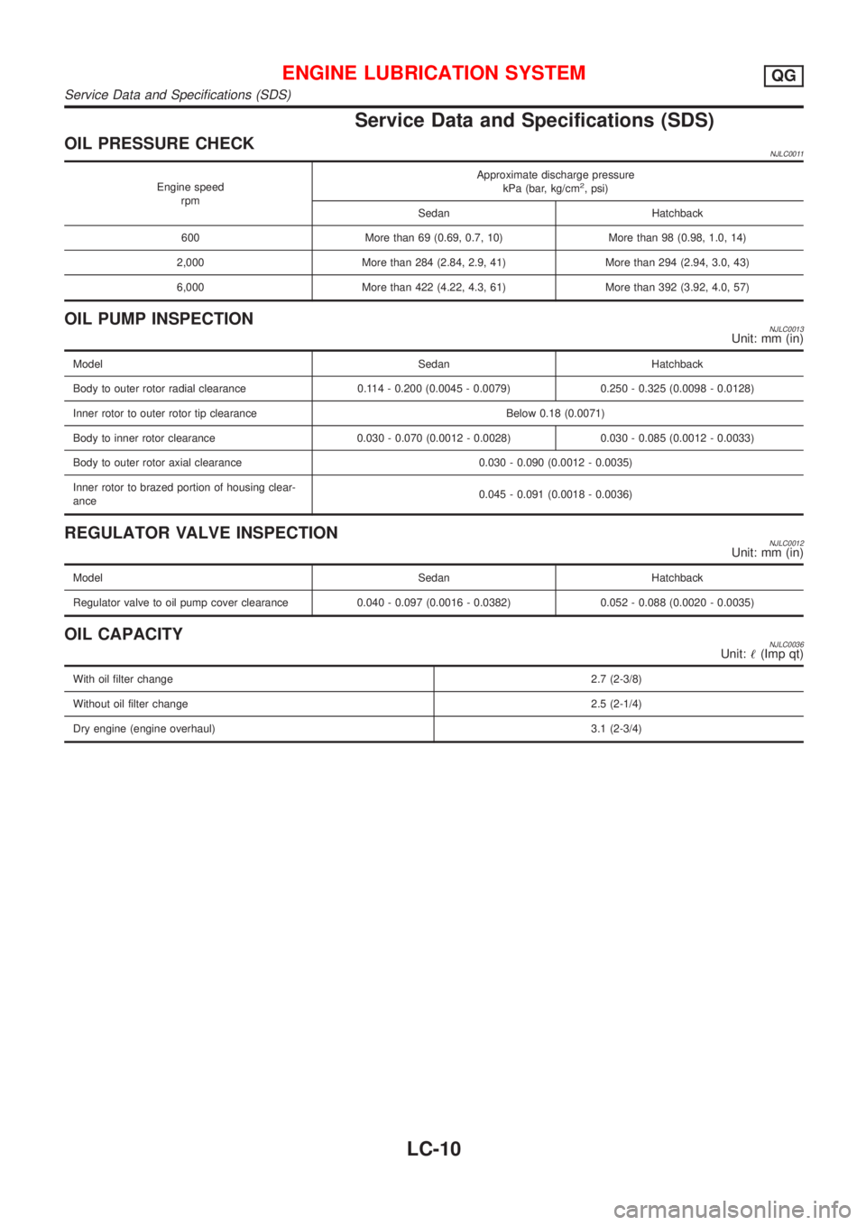
Service Data and Specifications (SDS)
OIL PRESSURE CHECKNJLC0011
Engine speed
rpmApproximate discharge pressure
kPa (bar, kg/cm2, psi)
Sedan Hatchback
600 More than 69 (0.69, 0.7, 10) More than 98 (0.98, 1.0, 14)
2,000 More than 284 (2.84, 2.9, 41) More than 294 (2.94, 3.0, 43)
6,000 More than 422 (4.22, 4.3, 61) More than 392 (3.92, 4.0, 57)
OIL PUMP INSPECTIONNJLC0013Unit: mm (in)
Model Sedan Hatchback
Body to outer rotor radial clearance 0.114 - 0.200 (0.0045 - 0.0079) 0.250 - 0.325 (0.0098 - 0.0128)
Inner rotor to outer rotor tip clearance Below 0.18 (0.0071)
Body to inner rotor clearance 0.030 - 0.070 (0.0012 - 0.0028) 0.030 - 0.085 (0.0012 - 0.0033)
Body to outer rotor axial clearance 0.030 - 0.090 (0.0012 - 0.0035)
Inner rotor to brazed portion of housing clear-
ance0.045 - 0.091 (0.0018 - 0.0036)
REGULATOR VALVE INSPECTIONNJLC0012Unit: mm (in)
Model Sedan Hatchback
Regulator valve to oil pump cover clearance 0.040 - 0.097 (0.0016 - 0.0382) 0.052 - 0.088 (0.0020 - 0.0035)
OIL CAPACITYNJLC0036Unit:!(Imp qt)
With oil filter change2.7 (2-3/8)
Without oil filter change2.5 (2-1/4)
Dry engine (engine overhaul)3.1 (2-3/4)
ENGINE LUBRICATION SYSTEMQG
Service Data and Specifications (SDS)
LC-10
Page 2537 of 2898
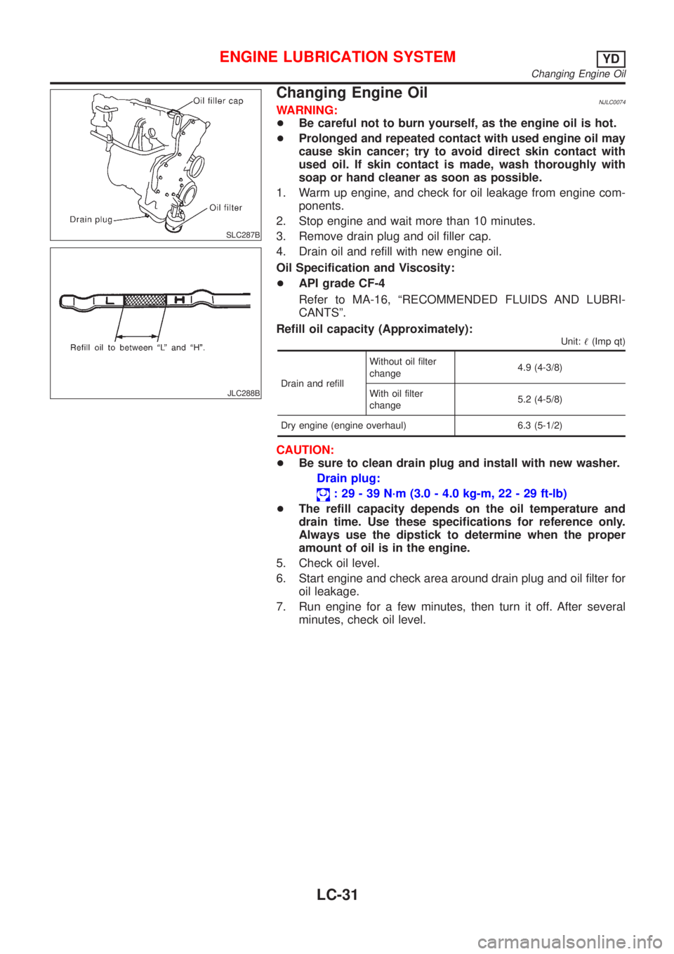
SLC287B
JLC288B
Changing Engine OilNJLC0074WARNING:
+Be careful not to burn yourself, as the engine oil is hot.
+Prolonged and repeated contact with used engine oil may
cause skin cancer; try to avoid direct skin contact with
used oil. If skin contact is made, wash thoroughly with
soap or hand cleaner as soon as possible.
1. Warm up engine, and check for oil leakage from engine com-
ponents.
2. Stop engine and wait more than 10 minutes.
3. Remove drain plug and oil filler cap.
4. Drain oil and refill with new engine oil.
Oil Specification and Viscosity:
+API grade CF-4
Refer to MA-16, ªRECOMMENDED FLUIDS AND LUBRI-
CANTSº.
Refill oil capacity (Approximately):
Unit:!(Imp qt)
Drain and refillWithout oil filter
change4.9 (4-3/8)
With oil filter
change5.2 (4-5/8)
Dry engine (engine overhaul) 6.3 (5-1/2)
CAUTION:
+Be sure to clean drain plug and install with new washer.
Drain plug:
: 29 - 39 N´m (3.0 - 4.0 kg-m, 22 - 29 ft-lb)
+The refill capacity depends on the oil temperature and
drain time. Use these specifications for reference only.
Always use the dipstick to determine when the proper
amount of oil is in the engine.
5. Check oil level.
6. Start engine and check area around drain plug and oil filter for
oil leakage.
7. Run engine for a few minutes, then turn it off. After several
minutes, check oil level.
ENGINE LUBRICATION SYSTEMYD
Changing Engine Oil
LC-31
Page 2541 of 2898
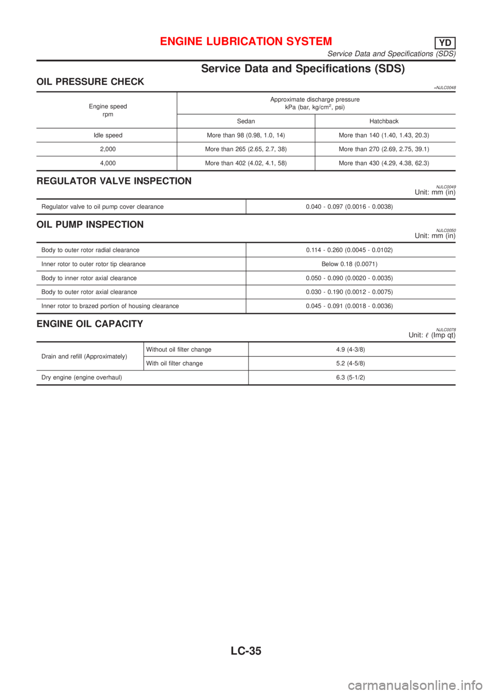
Service Data and Specifications (SDS)
OIL PRESSURE CHECK=NJLC0048
Engine speed
rpmApproximate discharge pressure
kPa (bar, kg/cm2, psi)
Sedan Hatchback
Idle speed More than 98 (0.98, 1.0, 14) More than 140 (1.40, 1.43, 20.3)
2,000 More than 265 (2.65, 2.7, 38) More than 270 (2.69, 2.75, 39.1)
4,000 More than 402 (4.02, 4.1, 58) More than 430 (4.29, 4.38, 62.3)
REGULATOR VALVE INSPECTIONNJLC0049Unit: mm (in)
Regulator valve to oil pump cover clearance 0.040 - 0.097 (0.0016 - 0.0038)
OIL PUMP INSPECTIONNJLC0050Unit: mm (in)
Body to outer rotor radial clearance 0.114 - 0.260 (0.0045 - 0.0102)
Inner rotor to outer rotor tip clearance Below 0.18 (0.0071)
Body to inner rotor axial clearance 0.050 - 0.090 (0.0020 - 0.0035)
Body to outer rotor axial clearance 0.030 - 0.190 (0.0012 - 0.0075)
Inner rotor to brazed portion of housing clearance 0.045 - 0.091 (0.0018 - 0.0036)
ENGINE OIL CAPACITYNJLC0078Unit:!(Imp qt)
Drain and refill (Approximately)Without oil filter change 4.9 (4-3/8)
With oil filter change 5.2 (4-5/8)
Dry engine (engine overhaul)6.3 (5-1/2)
ENGINE LUBRICATION SYSTEMYD
Service Data and Specifications (SDS)
LC-35