cylinder bore NISSAN ALMERA 2001 Service Manual
[x] Cancel search | Manufacturer: NISSAN, Model Year: 2001, Model line: ALMERA, Model: NISSAN ALMERA 2001Pages: 2898, PDF Size: 60.76 MB
Page 616 of 2898
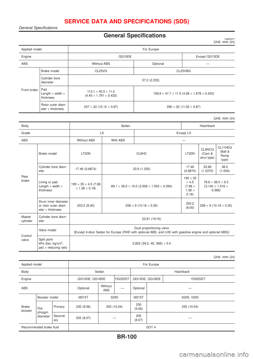
General SpecificationsNJBR0077Unit: mm (in)
Applied model For Europe
Engine QG15DE Except QG15DE
ABS Without ABS Optional Ð
Front brakeBrake model CL25VG CL25VBG
Cylinder bore
diameter57.2 (2.252)
Pad
Length´width´
thickness113.1´45.5´11.0
(4.45´1.791´0.433)108.8´47.7´11.0 (4.28´1.878´0.433)
Rotor outer diam-
eter´thickness257´22 (10.12´0.87) 280´22 (11.02´0.87)
Unit: mm (in)
Body Sedan Hatchback
Grade LX Except LX
ABS Without ABS With ABS Ð
Rear
brakeBrake model LT20N CL9HC LT20NCL9HCG
(Cam &
strut type)CL11HEG
(Ball &
Ramp
type)
Cylinder bore diam-
eter17.46 (0.6874) 33.9 (1.335)17.46
(0.6874)33.96
(1.3370)38.2
(1.504)
Lining or pad
Length´width´
thickness195´35´4.5 (7.68
´1.38´0.18)89.1´39.5´10.0 (3.508´1.555´0.394)195´35
´4.5
(7.68´
1.38´
0.18)79.8´38.5´9.3
(3.142´1.516´
0.366)
Drum inner diameter
or rotor outer diam-
eter´thickness203.2 (8.00) 258´9 (10.16´0.35)203.2
(8.00)258´9 (10.16´0.35)
Master
cylinderCylinder bore diam-
eter23.81 (15/16)
Control
valveValve modelDual proportioning valve
[Except 4-door Sedan for Europe (RHD with optional ABS, and LHD with gasoline engine and optional ABS)]
Split point
kPa (bar, kg/cm
2,
psi)´reducing ratio3,923 (39.2, 40, 569)´0.4
Unit: mm (in)
Applied model For Europe
Body Sedan Hatchback
Engine QG15DE, QG18DE YD22DDT QG15DE, QG18DE YD22DDT
ABS OptionalWithout
ABSÐ Optional Ð
Brake
boosterBooster model M215T S255 M215T S255, V255
Dia-
phragm
diameterPrimary 230 (9.06) 255 (10.04)230
(9.06)255 (10.04)
Second-
ary205 (8.07) Ð205
(8.07)Ð
Recommended brake fluid DOT 4
SERVICE DATA AND SPECIFICATIONS (SDS)
General Specifications
BR-100
Page 2135 of 2898
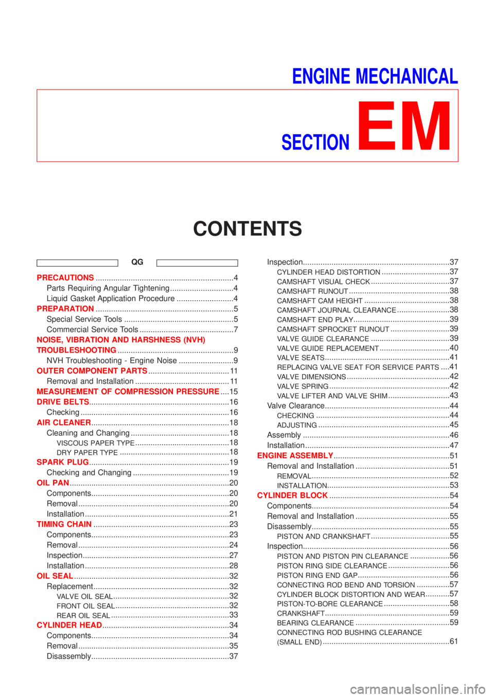
ENGINE MECHANICAL
SECTION
EM
CONTENTS
QG
PRECAUTIONS...............................................................4
Parts Requiring Angular Tightening .............................4
Liquid Gasket Application Procedure ..........................4
PREPARATION...............................................................5
Special Service Tools ..................................................5
Commercial Service Tools ...........................................7
NOISE, VIBRATION AND HARSHNESS (NVH)
TROUBLESHOOTING.....................................................9
NVH Troubleshooting - Engine Noise .........................9
OUTER COMPONENT PARTS..................................... 11
Removal and Installation ........................................... 11
MEASUREMENT OF COMPRESSION PRESSURE....15
DRIVE BELTS................................................................16
Checking ....................................................................16
AIR CLEANER...............................................................18
Cleaning and Changing .............................................18
VISCOUS PAPER TYPE...........................................18
DRY PAPER TYPE..................................................18
SPARK PLUG................................................................19
Checking and Changing ............................................19
OIL PAN.........................................................................20
Components...............................................................20
Removal .....................................................................20
Installation ..................................................................21
TIMING CHAIN..............................................................23
Components...............................................................23
Removal .....................................................................24
Inspection...................................................................27
Installation ..................................................................28
OIL SEAL.......................................................................32
Replacement ..............................................................32
VALVE OIL SEAL.....................................................32
FRONT OIL SEAL....................................................32
REAR OIL SEAL......................................................33
CYLINDER HEAD..........................................................34
Components...............................................................34
Removal .....................................................................35
Disassembly...............................................................37Inspection...................................................................37
CYLINDER HEAD DISTORTION...............................37
CAMSHAFT VISUAL CHECK....................................37
CAMSHAFT RUNOUT..............................................38
CAMSHAFT CAM HEIGHT.......................................38
CAMSHAFT JOURNAL CLEARANCE........................38
CAMSHAFT END PLAY............................................39
CAMSHAFT SPROCKET RUNOUT...........................39
VALVE GUIDE CLEARANCE....................................39
VALVE GUIDE REPLACEMENT................................40
VALVE SEATS.........................................................41
REPLACING VALVE SEAT FOR SERVICE PARTS....41
VALVE DIMENSIONS...............................................42
VALVE SPRING.......................................................42
VALVE LIFTER AND VALVE SHIM............................43
Valve Clearance.........................................................44
CHECKING.............................................................44
ADJUSTING............................................................45
Assembly ...................................................................46
Installation ..................................................................47
ENGINE ASSEMBLY.....................................................51
Removal and Installation ...........................................51
REMOVAL...............................................................52
INSTALLATION........................................................53
CYLINDER BLOCK.......................................................54
Components...............................................................54
Removal and Installation ...........................................55
Disassembly...............................................................55
PISTON AND CRANKSHAFT....................................55
Inspection...................................................................56
PISTON AND PISTON PIN CLEARANCE..................56
PISTON RING SIDE CLEARANCE............................56
PISTON RING END GAP..........................................56
CONNECTING ROD BEND AND TORSION...............57
CYLINDER BLOCK DISTORTION AND WEAR...........57
PISTON-TO-BORE CLEARANCE..............................58
CRANKSHAFT.........................................................59
BEARING CLEARANCE...........................................59
CONNECTING ROD BUSHING CLEARANCE
(SMALL END)
..........................................................61
Page 2137 of 2898
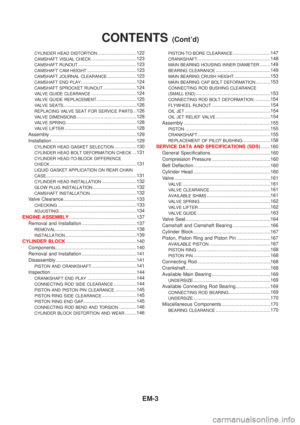
CYLINDER HEAD DISTORTION.............................122
CAMSHAFT VISUAL CHECK..................................123
CAMSHAFT RUNOUT............................................123
CAMSHAFT CAM HEIGHT.....................................123
CAMSHAFT JOURNAL CLEARANCE......................123
CAMSHAFT END PLAY..........................................124
CAMSHAFT SPROCKET RUNOUT.........................124
VALVE GUIDE CLEARANCE..................................124
VALVE GUIDE REPLACEMENT..............................125
VALVE SEATS.......................................................126
REPLACING VALVE SEAT FOR SERVICE PARTS..126
VALVE DIMENSIONS.............................................128
VALVE SPRING.....................................................128
VALVE LIFTER......................................................128
Assembly .................................................................129
Installation ................................................................129
CYLINDER HEAD GASKET SELECTION.................130
CYLINDER HEAD BOLT DEFORMATION CHECK...131
CYLINDER HEAD-TO-BLOCK DIFFERENCE
CHECK
.................................................................131
LIQUID GASKET APPLICATION ON REAR CHAIN
CASE
....................................................................131
CYLINDER HEAD INSTALLATION..........................132
GLOW PLUG INSTALLATION.................................132
CAMSHAFT INSTALLATION...................................132
Valve Clearance.......................................................133
CHECKING...........................................................133
ADJUSTING..........................................................134
ENGINE ASSEMBLY...................................................137
Removal and Installation .........................................137
REMOVAL.............................................................138
INSTALLATION......................................................139
CYLINDER BLOCK.....................................................140
Components.............................................................140
Removal and Installation .........................................141
Disassembly.............................................................141
PISTON AND CRANKSHAFT..................................141
Inspection.................................................................144
CRANKSHAFT END PLAY.....................................144
CONNECTING ROD SIDE CLEARANCE.................144
PISTON AND PISTON PIN CLEARANCE................145
PISTON RING SIDE CLEARANCE..........................145
PISTON RING END GAP........................................145
CONNECTING ROD BEND AND TORSION.............146
CYLINDER BLOCK DISTORTION AND WEAR.........146
PISTON-TO-BORE CLEARANCE............................147
CRANKSHAFT.......................................................148
MAIN BEARING HOUSING INNER DIAMETER........149
BEARING CLEARANCE.........................................149
MAIN BEARING CRUSH HEIGHT...........................153
MAIN BEARING CAP BOLT DEFORMATION...........153
CONNECTING ROD BUSHING CLEARANCE
(SMALL END)
........................................................153
CONNECTING ROD BOLT DEFORMATION............154
FLYWHEEL RUNOUT............................................154
OIL JET................................................................154
OIL JET RELIEF VALVE.........................................154
Assembly .................................................................155
PISTON................................................................155
CRANKSHAFT.......................................................155
REPLACEMENT OF PILOT BUSHING.....................158
SERVICE DATA AND SPECIFICATIONS (SDS).......160
General Specifications .............................................160
Compression Pressure ............................................160
Belt Deflection..........................................................160
Cylinder Head ..........................................................160
Valve ........................................................................161
VALVE..................................................................161
VALVE CLEARANCE..............................................161
AVAILABLE SHIMS................................................161
VALVE SPRING.....................................................162
VALVE LIFTER......................................................162
VALVE GUIDE.......................................................163
Valve Seat................................................................164
Camshaft and Camshaft Bearing ............................166
Cylinder Block ..........................................................167
Piston, Piston Ring and Piston Pin .........................167
AVAILABLE PISTON..............................................167
PISTON RING.......................................................168
PISTON PIN..........................................................168
Connecting Rod .......................................................168
Crankshaft................................................................168
Available Main Bearing ............................................169
UNDERSIZE..........................................................169
Available Connecting Rod Bearing..........................169
CONNECTING ROD BEARING...............................169
UNDERSIZE..........................................................170
Miscellaneous Components.....................................170
BEARING CLEARANCE.........................................170
CONTENTS(Cont'd)
EM-3
Page 2140 of 2898
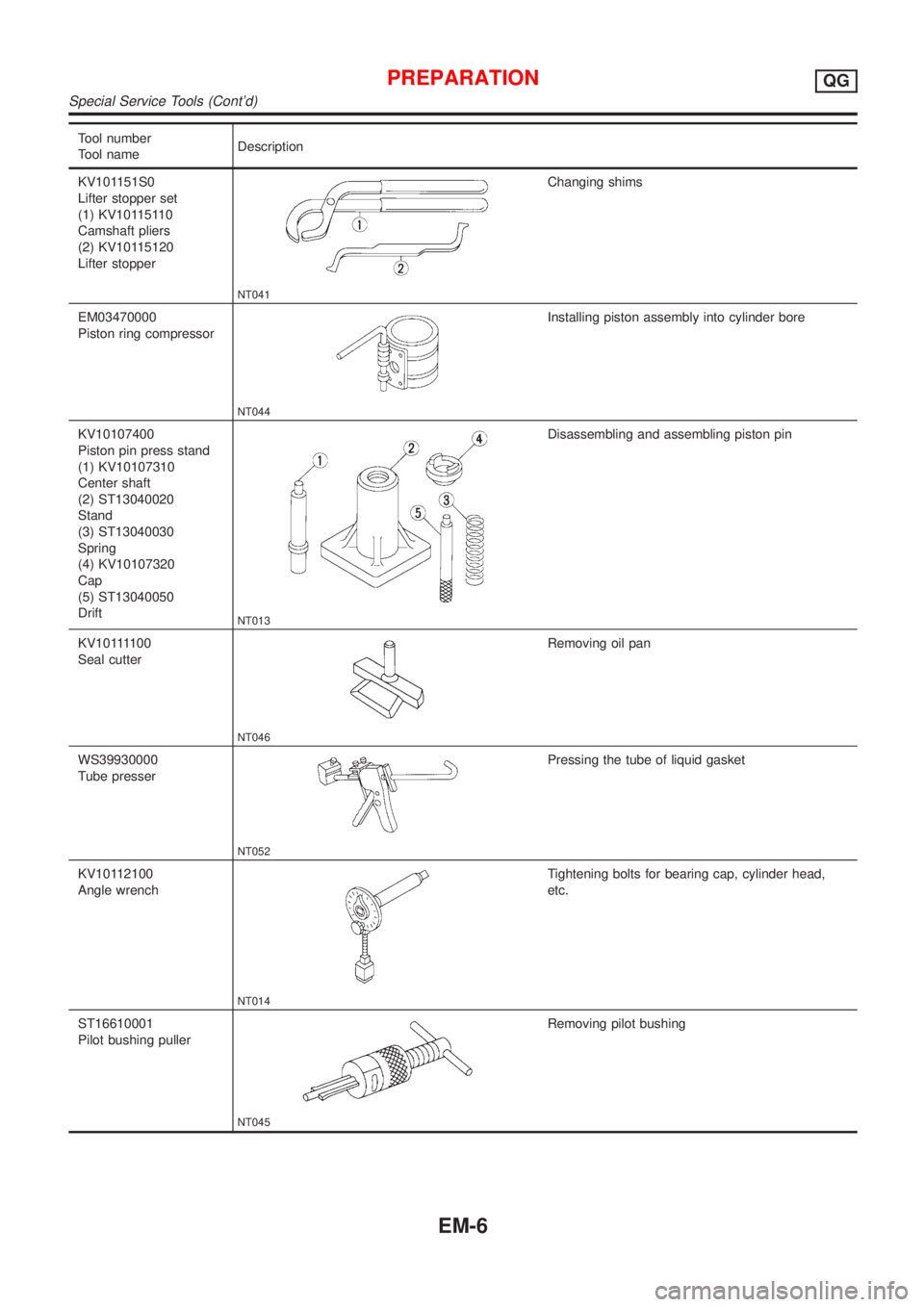
Tool number
Tool nameDescription
KV101151S0
Lifter stopper set
(1) KV10115110
Camshaft pliers
(2) KV10115120
Lifter stopper
NT041
Changing shims
EM03470000
Piston ring compressor
NT044
Installing piston assembly into cylinder bore
KV10107400
Piston pin press stand
(1) KV10107310
Center shaft
(2) ST13040020
Stand
(3) ST13040030
Spring
(4) KV10107320
Cap
(5) ST13040050
Drift
NT013
Disassembling and assembling piston pin
KV101111 0 0
Seal cutter
NT046
Removing oil pan
WS39930000
Tube presser
NT052
Pressing the tube of liquid gasket
KV10112100
Angle wrench
NT014
Tightening bolts for bearing cap, cylinder head,
etc.
ST16610001
Pilot bushing puller
NT045
Removing pilot bushing
PREPARATIONQG
Special Service Tools (Cont'd)
EM-6
Page 2143 of 2898

NJEM0005
NVH Troubleshooting Ð Engine NoiseNJEM0005S01Use the chart below to help you find the cause of the symptom.
1. Locate the area where noise occurs.
2. Confirm the type of noise.
3. Specify the operating condition of engine.
4. Check specified noise source.
If necessary, repair or replace these parts.
Location of
noiseType of
noiseOperating condition of engine
Source of
noiseCheck itemReference
page Before
warm-
upAfter
warm-
upWhen
start-
ingWhen
idlingWhen
racingWhile
driving
To p o f
Engine
Rocket
Cover Cyl-
inder HeadTicking or
clickC A Ð A B Ð Tappet
noise+Valve clearance EM-44
Rattle C A Ð A B C Camshaft
bearing
noise+Camshaft journal
clearance
+Camshaft runoutEM-38
Crankshaft
Pulley
Cylinder
block (Side
of Engine)
Oil panSlap or
knockÐ A Ð B B Ð Piston pin
noise+Piston and piston pin
clearance
+Connecting rod bush-
ing clearanceEM-56, 61
Slap or
rapA Ð Ð B B A Piston slap
noise+Piston-to-bore clear-
ance
+Piston ring side clear-
ance
+Piston ring end gap
+Connecting rod bend
and torsionEM-56, 57,
58
Knock A B CB B B Connecting
rod-bearing
noise+Connecting rod bear-
ing clearance (Big
end)
+Connecting rod bush-
ing clearance (Small
end)EM-60, 61
Knock A B Ð A B C Main bear-
ing noise+Main bearing oil clear-
ance
+Crankshaft runoutEM-59
Front of
Engine Tim-
ing Chain
CoverTapping or
tickingAAÐBBBTiming
chain and
chain ten-
sioner noise+Timing chain cracks
and wear
+Timing chain tensioner
operationEM-27
Front of
EngineSqueak or
fizzingA B Ð B Ð C Other drive
belts (stick-
ing or slip-
ping)+Drive belts deflection EM-16
CreakingABABABOther drive
belts (slip-
ping)+Idler pulley bearing
operation
Squall or
creakABÐBABWater pump
noise+Water pump operation LC-14
A: Closely related B: Related C: Sometimes related Ð: Not related
NOISE, VIBRATION AND HARSHNESS (NVH) TROUBLESHOOTINGQG
NVH Troubleshooting Ð Engine Noise
EM-9
Page 2175 of 2898

MEM096A
4. Heat cylinder head to 110 to 130ÉC (230 to 266ÉF) and press
service valve guide into cylinder head.
Projection ªLº:
11.5 - 11.7 mm (0.453 - 0.461 in)
SEM932C
5. Ream valve guide.
Finished size:
Intake & Exhaust
5.500 - 5.515 mm (0.2165 - 0.2171 in)
SEM934C
VALVE SEATSNJEM0019S10Check valve seats for pitting at contact surface. Resurface or
replace if excessively worn.
+Before repairing valve seats, check valve and valve guide
for wear. If they have worn, replace them. Then correct
valve seat.
+Use both hands to cut uniformly.
SEM795A
REPLACING VALVE SEAT FOR SERVICE PARTSNJEM0019S111. Bore out old seat until it collapses. Set machine depth stop so
that boring cannot contact the bottom face of seat recess in
cylinder head.
2. Ream cylinder head recess.
Reaming bore for service valve seat
Oversize [0.5 mm (0.020 in)]:
Refer to SDS, EM-71.
Use the valve guide center for reaming to ensure valve seat
will have the correct fit.
SEM008A
3. Heat cylinder head to 110 to 130ÉC (230 to 266ÉF).
4. Press fit valve seat until it seats on the bottom.
CYLINDER HEADQG
Inspection (Cont'd)
EM-41
Page 2177 of 2898

EM113
PressureNJEM0019S1302Check valve spring pressure at specified spring height.
Pressure:
For Sedan
Standard
344.42 N (35.12 kg, 77.44 lb) at 25.26 mm (0.9945
in)
Limit
More than 323.73 N (33.01 kg, 72.79 lb) at 25.26
mm (0.9945 in)
For Hatchback
Standard
370.0 N (37.73 kg, 83.19 lb) at 23.64 mm (0.9307 in)
Limit
More than 347.8 N (35.46 kg, 78.19 lb) at 23.64 mm
(0.9307 in)
If it exceeds the limit, replace spring.
SEM160D
VALVE LIFTER AND VALVE SHIMNJEM0019S161. Check contact and sliding surfaces for wear or scratches.
SEM161D
2. Check diameter of valve lifter and valve lifter guide bore.
Valve lifter outside diameter:
29.960 - 29.975 mm (1.1795 - 1.1801 in)
SEM920F
Lifter guide inside diameter:
30.000 - 30.021 mm (1.1811 - 1.1819 in)
Clearance between valve lifter and valve lifter guide:
0.025 - 0.065 mm (0.0010 - 0.0026 in)
If it exceeds the limit, replace valve lifter or cylinder head which
exceeds the standard diameter tolerance.
CYLINDER HEADQG
Inspection (Cont'd)
EM-43
Page 2190 of 2898

SEM928F
7. Remove signal plate from crankshaft.
AEM023
InspectionNJEM0026PISTON AND PISTON PIN CLEARANCENJEM0026S011. Measure inner diameter of piston pin hole ªdpº.
Standard diameter ªdpº:
QG18DE
18.993 - 19.005 mm (0.7478 - 0.7482 in)
Except for QG18DE
18.987 - 18.999 mm (0.7475 - 0.7480 in)
AEM024
2. Measure outer diameter of piston pin ªDpº.
Standard diameter ªDpº:
18.989 - 19.001 mm (0.7476 - 0.7481 in)
3. Calculate piston pin clearance.
QG18DE
Dp þ dp: 0.002 - 0.006 mm (0.0001 - 0.0002 in)
Except for QG18DE
Dp þ dp: þ0.004 to 0 mm (þ0.0002 to 0 in)
If it exceeds the above value, replace piston assembly with pin.
SEM024AA
PISTON RING SIDE CLEARANCENJEM0026S02Side clearance:
Refer to SDS, EM-74.
Max. limit of side clearance:
Refer to SDS, EM-74.
If out of specification, replace piston and/or piston ring assembly.
AEM096
PISTON RING END GAPNJEM0026S03End gap:
Refer to SDS, EM-74.
Max. limit of end gap:
Refer to SDS, EM-74.
If out of specification, replace piston ring. If gap exceeds maximum
limit with a new ring, rebore cylinder and use oversized piston and
piston rings.
Refer to SDS, EM-74.
+When replacing the piston, check the cylinder bore surface for
CYLINDER BLOCKQG
Disassembly (Cont'd)
EM-56
Page 2192 of 2898
SEM166D
SEM929F
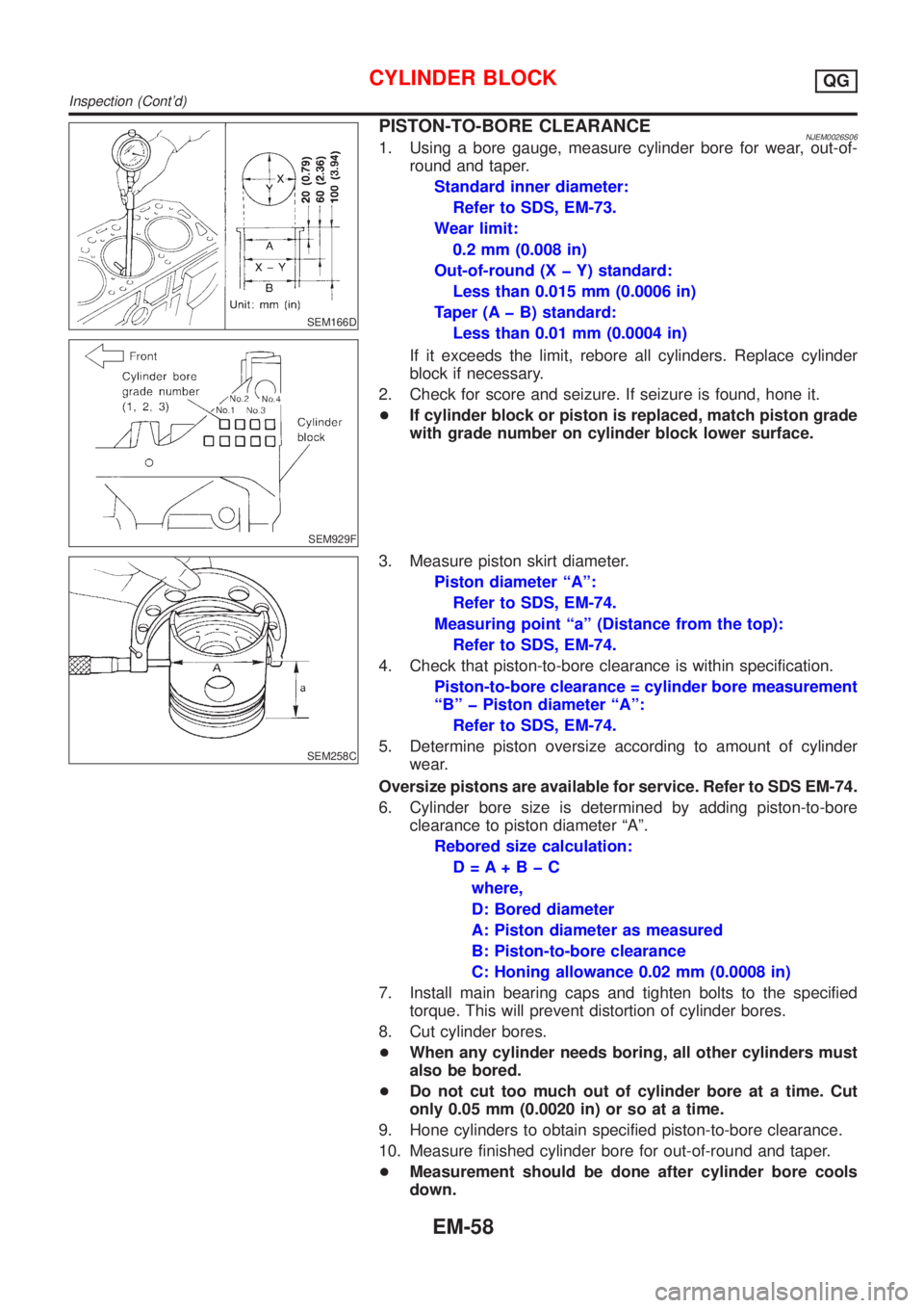
PISTON-TO-BORE CLEARANCENJEM0026S061. Using a bore gauge, measure cylinder bore for wear, out-of-
round and taper.
Standard inner diameter:
Refer to SDS, EM-73.
Wear limit:
0.2 mm (0.008 in)
Out-of-round (X þ Y) standard:
Less than 0.015 mm (0.0006 in)
Taper (A þ B) standard:
Less than 0.01 mm (0.0004 in)
If it exceeds the limit, rebore all cylinders. Replace cylinder
block if necessary.
2. Check for score and seizure. If seizure is found, hone it.
+If cylinder block or piston is replaced, match piston grade
with grade number on cylinder block lower surface.
SEM258C
3. Measure piston skirt diameter.
Piston diameter ªAº:
Refer to SDS, EM-74.
Measuring point ªaº (Distance from the top):
Refer to SDS, EM-74.
4. Check that piston-to-bore clearance is within specification.
Piston-to-bore clearance = cylinder bore measurement
ªBº þ Piston diameter ªAº:
Refer to SDS, EM-74.
5. Determine piston oversize according to amount of cylinder
wear.
Oversize pistons are available for service. Refer to SDS EM-74.
6. Cylinder bore size is determined by adding piston-to-bore
clearance to piston diameter ªAº.
Rebored size calculation:
D=A+BþC
where,
D: Bored diameter
A: Piston diameter as measured
B: Piston-to-bore clearance
C: Honing allowance 0.02 mm (0.0008 in)
7. Install main bearing caps and tighten bolts to the specified
torque. This will prevent distortion of cylinder bores.
8. Cut cylinder bores.
+When any cylinder needs boring, all other cylinders must
also be bored.
+Do not cut too much out of cylinder bore at a time. Cut
only 0.05 mm (0.0020 in) or so at a time.
9. Hone cylinders to obtain specified piston-to-bore clearance.
10. Measure finished cylinder bore for out-of-round and taper.
+Measurement should be done after cylinder bore cools
down.
CYLINDER BLOCKQG
Inspection (Cont'd)
EM-58
Page 2193 of 2898
SEM316A
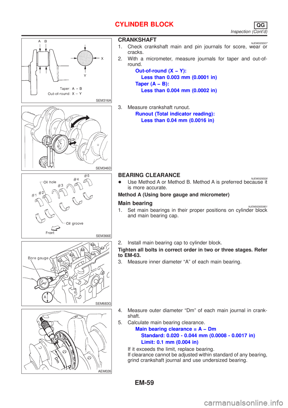
CRANKSHAFTNJEM0026S071. Check crankshaft main and pin journals for score, wear or
cracks.
2. With a micrometer, measure journals for taper and out-of-
round.
Out-of-round (X þ Y):
Less than 0.003 mm (0.0001 in)
Taper (A þ B):
Less than 0.004 mm (0.0002 in)
SEM346D
3. Measure crankshaft runout.
Runout (Total indicator reading):
Less than 0.04 mm (0.0016 in)
SEM366E
BEARING CLEARANCENJEM0026S08+Use Method A or Method B. Method A is preferred because it
is more accurate.
Method A (Using bore gauge and micrometer)
Main bearingNJEM0026S08011. Set main bearings in their proper positions on cylinder block
and main bearing cap.
SEM683G
2. Install main bearing cap to cylinder block.
Tighten all bolts in correct order in two or three stages. Refer
to EM-63.
3. Measure inner diameter ªAº of each main bearing.
AEM026
4. Measure outer diameter ªDmº of each main journal in crank-
shaft.
5. Calculate main bearing clearance.
Main bearing clearance = A þ Dm
Standard: 0.020 - 0.044 mm (0.0008 - 0.0017 in)
Limit: 0.1 mm (0.004 in)
If it exceeds the limit, replace bearing.
If clearance cannot be adjusted within standard of any bearing,
grind crankshaft journal and use undersized bearing.
CYLINDER BLOCKQG
Inspection (Cont'd)
EM-59