fuel consumption NISSAN ALMERA 2001 Service Manual
[x] Cancel search | Manufacturer: NISSAN, Model Year: 2001, Model line: ALMERA, Model: NISSAN ALMERA 2001Pages: 2898, PDF Size: 60.76 MB
Page 879 of 2898
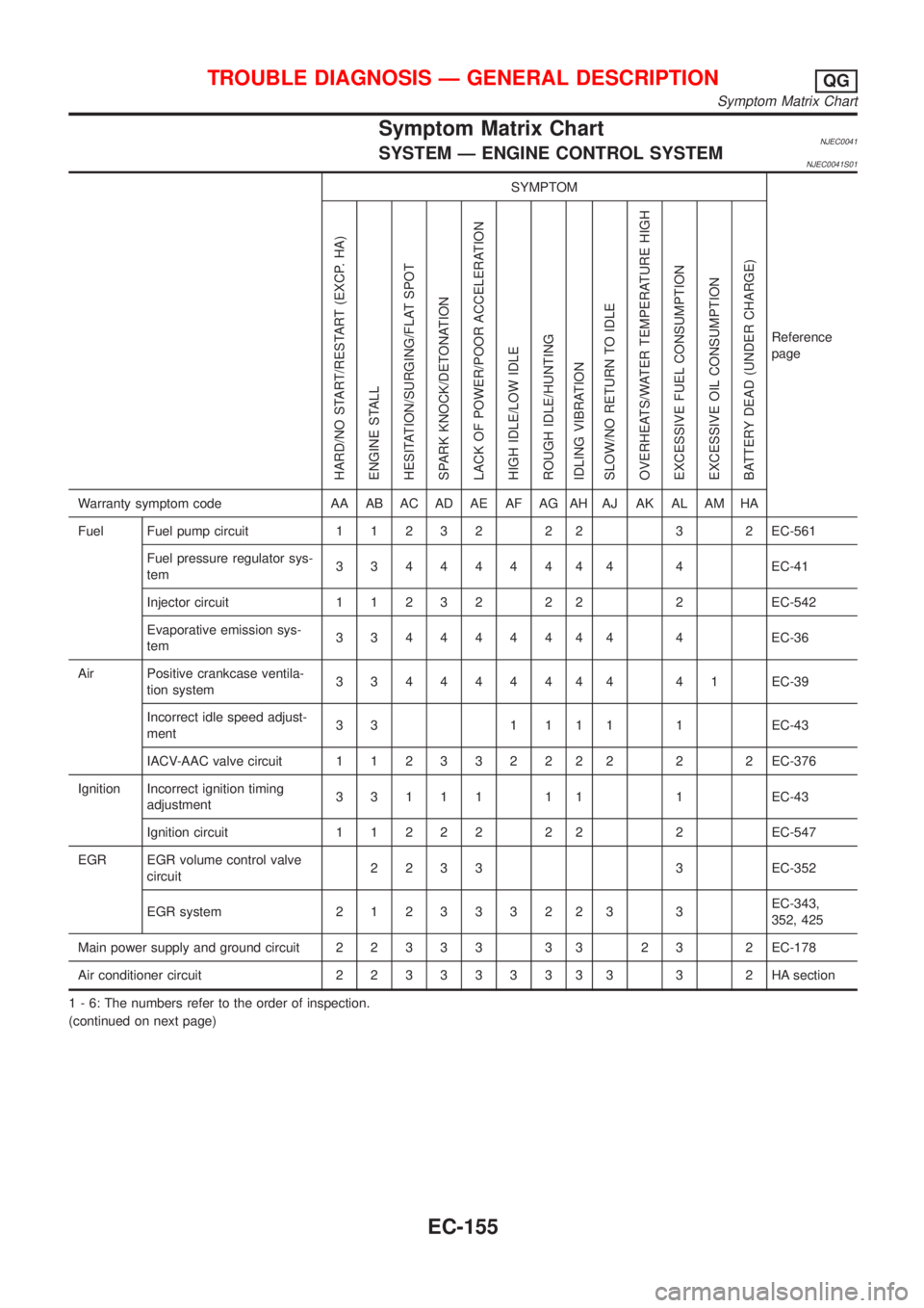
Symptom Matrix ChartNJEC0041SYSTEM Ð ENGINE CONTROL SYSTEMNJEC0041S01
SYMPTOM
Reference
page
HARD/NO START/RESTART (EXCP. HA)
ENGINE STALL
HESITATION/SURGING/FLAT SPOT
SPARK KNOCK/DETONATION
LACK OF POWER/POOR ACCELERATION
HIGH IDLE/LOW IDLE
ROUGH IDLE/HUNTING
IDLING VIBRATION
SLOW/NO RETURN TO IDLE
OVERHEATS/WATER TEMPERATURE HIGH
EXCESSIVE FUEL CONSUMPTION
EXCESSIVE OIL CONSUMPTION
BATTERY DEAD (UNDER CHARGE)
Warranty symptom code AA AB AC AD AE AF AG AH AJ AK AL AM HA
Fuel Fuel pump circuit11232 22 3 2EC-561
Fuel pressure regulator sys-
tem334444444 4EC-41
Injector circuit11232 22 2EC-542
Evaporative emission sys-
tem334444444 4EC-36
Air Positive crankcase ventila-
tion system334444444 41EC-39
Incorrect idle speed adjust-
ment3 3 1 1 1 1 1 EC-43
IACV-AAC valve circuit112332222 2 2EC-376
Ignition Incorrect ignition timing
adjustment33111 11 1EC-43
Ignition circuit11222 22 2EC-547
EGR EGR volume control valve
circuit2233 3EC-352
EGR system212333223 3EC-343,
352, 425
Main power supply and ground circuit22333 33 23 2EC-178
Air conditioner circuit223333333 3 2HAsection
1 - 6: The numbers refer to the order of inspection.
(continued on next page)
TROUBLE DIAGNOSIS Ð GENERAL DESCRIPTIONQG
Symptom Matrix Chart
EC-155
Page 880 of 2898
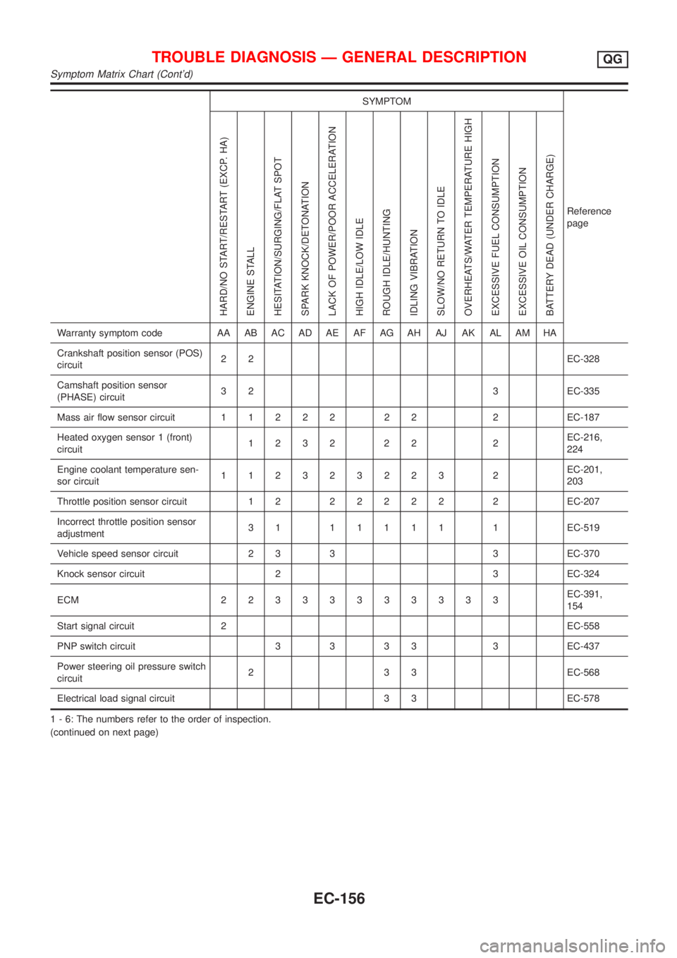
SYMPTOM
Reference
page
HARD/NO START/RESTART (EXCP. HA)
ENGINE STALL
HESITATION/SURGING/FLAT SPOT
SPARK KNOCK/DETONATION
LACK OF POWER/POOR ACCELERATION
HIGH IDLE/LOW IDLE
ROUGH IDLE/HUNTING
IDLING VIBRATION
SLOW/NO RETURN TO IDLE
OVERHEATS/WATER TEMPERATURE HIGH
EXCESSIVE FUEL CONSUMPTION
EXCESSIVE OIL CONSUMPTION
BATTERY DEAD (UNDER CHARGE)
Warranty symptom code AA AB AC AD AE AF AG AH AJ AK AL AM HA
Crankshaft position sensor (POS)
circuit22EC-328
Camshaft position sensor
(PHASE) circuit3 2 3 EC-335
Mass air flow sensor circuit11222 22 2EC-187
Heated oxygen sensor 1 (front)
circuit1232 22 2EC-216,
224
Engine coolant temperature sen-
sor circuit112323223 2EC-201,
203
Throttle position sensor circuit 1 222222 2EC-207
Incorrect throttle position sensor
adjustment31 11111 1EC-519
Vehicle speed sensor circuit 2 3 3 3 EC-370
Knock sensor circuit 2 3 EC-324
ECM 22333333333EC-391,
154
Start signal circuit 2EC-558
PNP switch circuit 3 3 3 3 3 EC-437
Power steering oil pressure switch
circuit2 3 3 EC-568
Electrical load signal circuit 3 3 EC-578
1 - 6: The numbers refer to the order of inspection.
(continued on next page)
TROUBLE DIAGNOSIS Ð GENERAL DESCRIPTIONQG
Symptom Matrix Chart (Cont'd)
EC-156
Page 881 of 2898
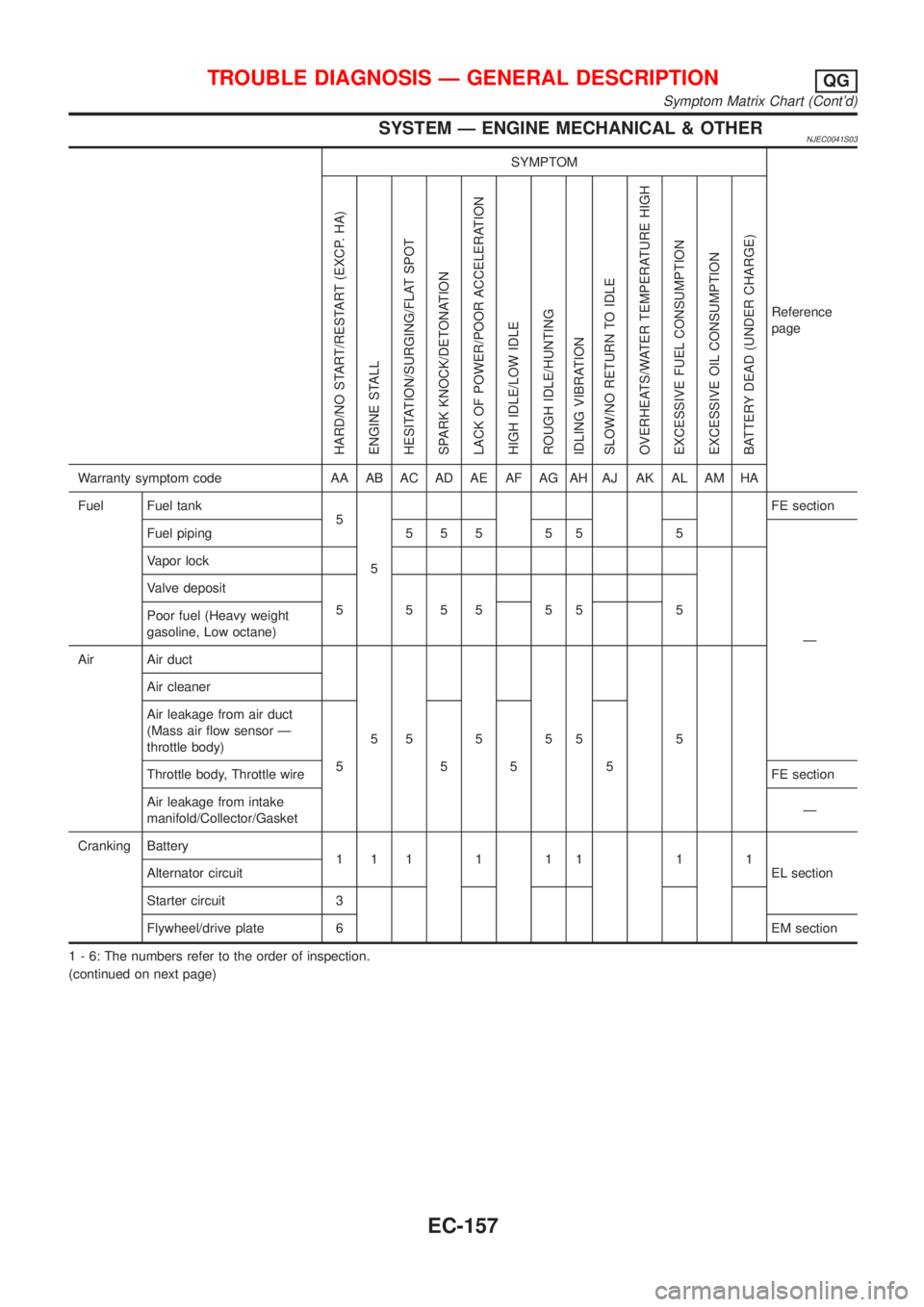
SYSTEM Ð ENGINE MECHANICAL & OTHERNJEC0041S03
SYMPTOM
Reference
page
HARD/NO START/RESTART (EXCP. HA)
ENGINE STALL
HESITATION/SURGING/FLAT SPOT
SPARK KNOCK/DETONATION
LACK OF POWER/POOR ACCELERATION
HIGH IDLE/LOW IDLE
ROUGH IDLE/HUNTING
IDLING VIBRATION
SLOW/NO RETURN TO IDLE
OVERHEATS/WATER TEMPERATURE HIGH
EXCESSIVE FUEL CONSUMPTION
EXCESSIVE OIL CONSUMPTION
BATTERY DEAD (UNDER CHARGE)
Warranty symptom code AA AB AC AD AE AF AG AH AJ AK AL AM HA
Fuel Fuel tank
5
5FE section
Fuel piping 5 5 5 5 5 5
Ð Vapor lock
Valve deposit
5 555 55 5
Poor fuel (Heavy weight
gasoline, Low octane)
Air Air duct
55555 5 Air cleaner
Air leakage from air duct
(Mass air flow sensor Ð
throttle body)
5555
Throttle body, Throttle wireFE section
Air leakage from intake
manifold/Collector/GasketÐ
Cranking Battery
111111 11
EL section Alternator circuit
Starter circuit 3
Flywheel/drive plate 6EM section
1 - 6: The numbers refer to the order of inspection.
(continued on next page)
TROUBLE DIAGNOSIS Ð GENERAL DESCRIPTIONQG
Symptom Matrix Chart (Cont'd)
EC-157
Page 882 of 2898
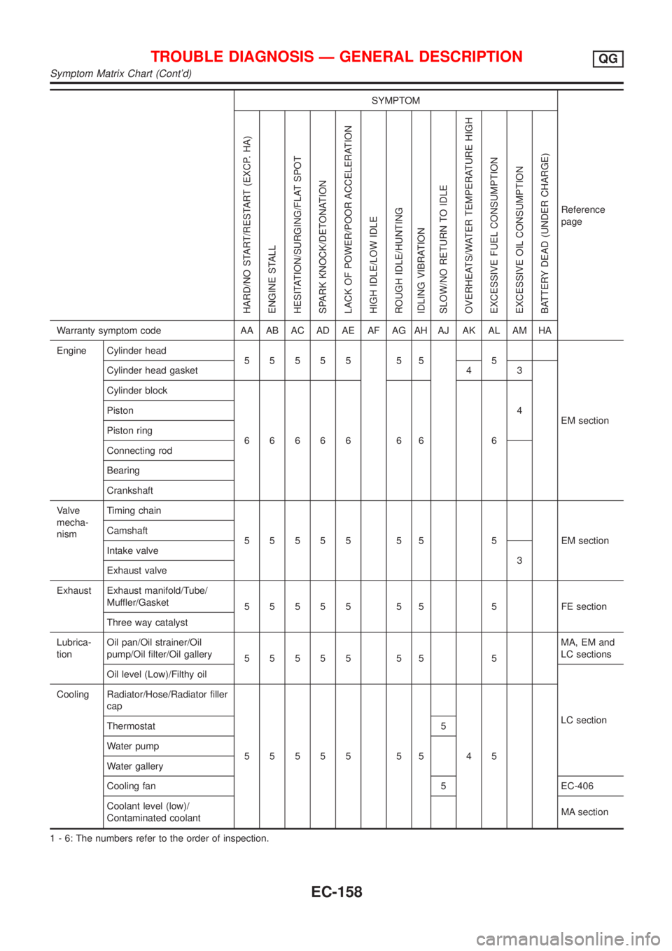
SYMPTOM
Reference
page
HARD/NO START/RESTART (EXCP. HA)
ENGINE STALL
HESITATION/SURGING/FLAT SPOT
SPARK KNOCK/DETONATION
LACK OF POWER/POOR ACCELERATION
HIGH IDLE/LOW IDLE
ROUGH IDLE/HUNTING
IDLING VIBRATION
SLOW/NO RETURN TO IDLE
OVERHEATS/WATER TEMPERATURE HIGH
EXCESSIVE FUEL CONSUMPTION
EXCESSIVE OIL CONSUMPTION
BATTERY DEAD (UNDER CHARGE)
Warranty symptom code AA AB AC AD AE AF AG AH AJ AK AL AM HA
Engine Cylinder head
55555 55 5
EM section Cylinder head gasket 4 3
Cylinder block
66666 66 64 Piston
Piston ring
Connecting rod
Bearing
Crankshaft
Valve
mecha-
nismTiming chain
55555 55 5 EMsection Camshaft
Intake valve
3
Exhaust valve
Exhaust Exhaust manifold/Tube/
Muffler/Gasket
55555 55 5 FEsection
Three way catalyst
Lubrica-
tionOil pan/Oil strainer/Oil
pump/Oil filter/Oil gallery
55555 55 5MA, EM and
LC sections
Oil level (Low)/Filthy oil
LC section Cooling Radiator/Hose/Radiator filler
cap
55555 55 45 Thermostat 5
Water pump
Water gallery
Cooling fan 5 EC-406
Coolant level (low)/
Contaminated coolantMA section
1 - 6: The numbers refer to the order of inspection.
TROUBLE DIAGNOSIS Ð GENERAL DESCRIPTIONQG
Symptom Matrix Chart (Cont'd)
EC-158
Page 1123 of 2898
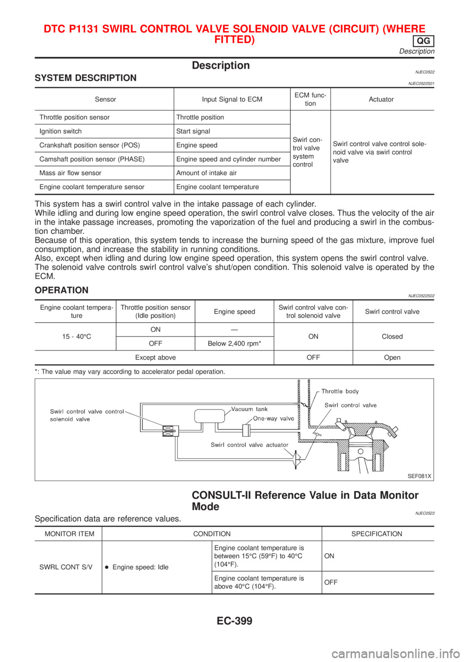
DescriptionNJEC0522SYSTEM DESCRIPTIONNJEC0522S01
Sensor Input Signal to ECMECM func-
tionActuator
Throttle position sensor Throttle position
Swirl con-
trol valve
system
controlSwirl control valve control sole-
noid valve via swirl control
valve Ignition switch Start signal
Crankshaft position sensor (POS) Engine speed
Camshaft position sensor (PHASE) Engine speed and cylinder number
Mass air flow sensor Amount of intake air
Engine coolant temperature sensor Engine coolant temperature
This system has a swirl control valve in the intake passage of each cylinder.
While idling and during low engine speed operation, the swirl control valve closes. Thus the velocity of the air
in the intake passage increases, promoting the vaporization of the fuel and producing a swirl in the combus-
tion chamber.
Because of this operation, this system tends to increase the burning speed of the gas mixture, improve fuel
consumption, and increase the stability in running conditions.
Also, except when idling and during low engine speed operation, this system opens the swirl control valve.
The solenoid valve controls swirl control valve's shut/open condition. This solenoid valve is operated by the
ECM.
OPERATIONNJEC0522S02
Engine coolant tempera-
tureThrottle position sensor
(Idle position)Engine speedSwirl control valve con-
trol solenoid valveSwirl control valve
15 - 40ÉCON Ð
ON Closed
OFF Below 2,400 rpm*
Except above OFF Open
*: The value may vary according to accelerator pedal operation.
SEF081X
CONSULT-II Reference Value in Data Monitor
Mode
NJEC0523Specification data are reference values.
MONITOR ITEM CONDITION SPECIFICATION
SWRL CONT S/V+Engine speed: IdleEngine coolant temperature is
between 15ÉC (59ÉF) to 40ÉC
(104ÉF).ON
Engine coolant temperature is
above 40ÉC (104ÉF).OFF
DTC P1131 SWIRL CONTROL VALVE SOLENOID VALVE (CIRCUIT) (WHERE
FITTED)
QG
Description
EC-399
Page 1199 of 2898
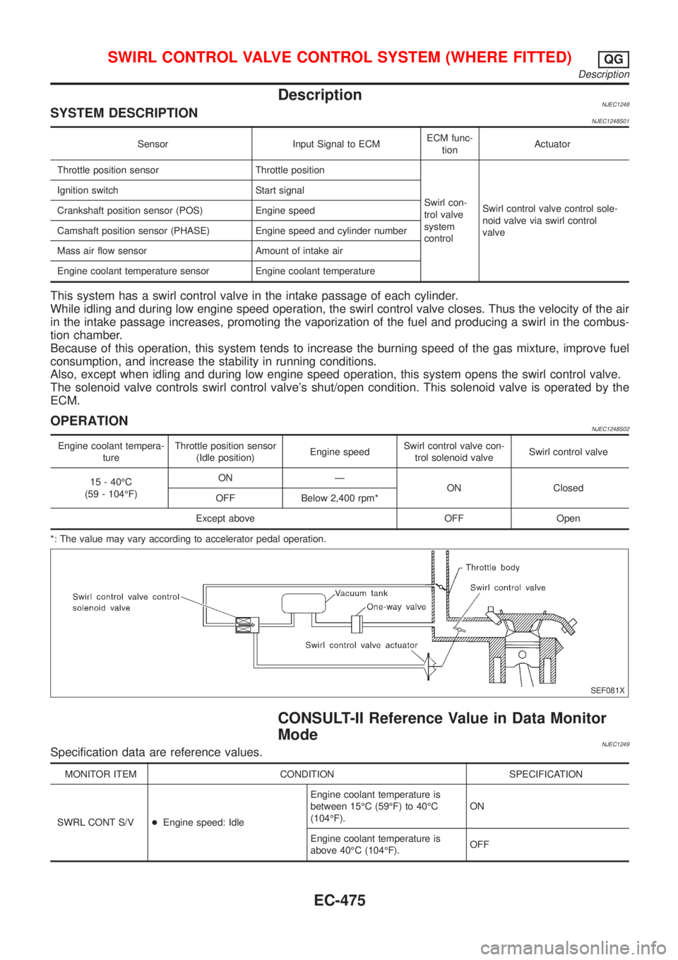
DescriptionNJEC1248SYSTEM DESCRIPTIONNJEC1248S01
Sensor Input Signal to ECMECM func-
tionActuator
Throttle position sensor Throttle position
Swirl con-
trol valve
system
controlSwirl control valve control sole-
noid valve via swirl control
valve Ignition switch Start signal
Crankshaft position sensor (POS) Engine speed
Camshaft position sensor (PHASE) Engine speed and cylinder number
Mass air flow sensor Amount of intake air
Engine coolant temperature sensor Engine coolant temperature
This system has a swirl control valve in the intake passage of each cylinder.
While idling and during low engine speed operation, the swirl control valve closes. Thus the velocity of the air
in the intake passage increases, promoting the vaporization of the fuel and producing a swirl in the combus-
tion chamber.
Because of this operation, this system tends to increase the burning speed of the gas mixture, improve fuel
consumption, and increase the stability in running conditions.
Also, except when idling and during low engine speed operation, this system opens the swirl control valve.
The solenoid valve controls swirl control valve's shut/open condition. This solenoid valve is operated by the
ECM.
OPERATIONNJEC1248S02
Engine coolant tempera-
tureThrottle position sensor
(Idle position)Engine speedSwirl control valve con-
trol solenoid valveSwirl control valve
15 - 40ÉC
(59 - 104ÉF)ON Ð
ON Closed
OFF Below 2,400 rpm*
Except above OFF Open
*: The value may vary according to accelerator pedal operation.
SEF081X
CONSULT-II Reference Value in Data Monitor
Mode
NJEC1249Specification data are reference values.
MONITOR ITEM CONDITION SPECIFICATION
SWRL CONT S/V+Engine speed: IdleEngine coolant temperature is
between 15ÉC (59ÉF) to 40ÉC
(104ÉF).ON
Engine coolant temperature is
above 40ÉC (104ÉF).OFF
SWIRL CONTROL VALVE CONTROL SYSTEM (WHERE FITTED)QG
Description
EC-475
Page 1371 of 2898
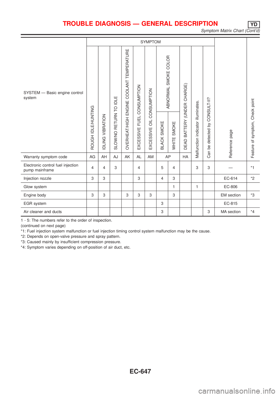
SYSTEM Ð Basic engine control
systemSYMPTOM
Reference page
Feature of symptom, Check pointROUGH IDLE/HUNTING
IDLING VIBRATION
SLOW/NO RETURN TO IDLE
OVERHEAT/HIGH ENGINE COOLANT TEMPERATURE
EXCESSIVE FUEL CONSUMPTION
EXCESSIVE OIL CONSUMPTION
ABNORMAL SMOKE COLOR
DEAD BATTERY (UNDER CHARGE)
Malfunction indicator illuminates.
Can be detected by CONSULT-II?BLACK SMOKE
WHITE SMOKEWarranty symptom code AG AH AJ AK AL AM AP HA
Electronic control fuel injection
pump mainframe44345433Ð*1
Injection nozzle 3 3 3 4 3 EC-614 *2
Glow system 1 1 EC-806
Engine body 3 3 3 3 3 3 EM section *3
EGR system 3 EC-815
Air cleaner and ducts 3 3 MA section *4
1 - 5: The numbers refer to the order of inspection.
(continued on next page)
*1: Fuel injection system malfunction or fuel injection timing control system malfunction may be the cause.
*2: Depends on open-valve pressure and spray pattern.
*3: Caused mainly by insufficient compression pressure.
*4: Symptom varies depending on off-position of air duct, etc.
TROUBLE DIAGNOSIS Ð GENERAL DESCRIPTIONYD
Symptom Matrix Chart (Cont'd)
EC-647
Page 1373 of 2898
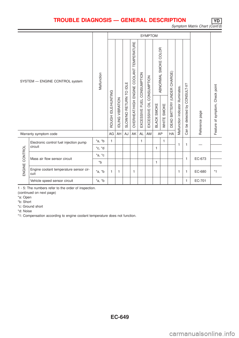
SYSTEM Ð ENGINE CONTROL system
Malfunction
SYMPTOM
Reference page
Feature of symptom, Check pointROUGH IDLE/HUNTING
IDLING VIBRATION
SLOW/NO RETURN TO IDLE
OVERHEAT/HIGH ENGINE COOLANT TEMPERATURE
EXCESSIVE FUEL CONSUMPTION
EXCESSIVE OIL CONSUMPTION
ABNORMAL SMOKE COLOR
DEAD BATTERY (UNDER CHARGE)
Malfunction indicator illuminates.
Can be detected by CONSULT-II?BLACK SMOKE
WHITE SMOKEWarranty symptom code AG AH AJ AK AL AM AP HA
ENGINE CONTROL
Electronic control fuel injection pump
circuit*a, *b 1 1 1
11 Ð
*c, *d 1
Mass air flow sensor circuit*a, *c
1 EC-673
*b 1
Engine coolant temperature sensor cir-
cuit*a, *b 1 1 1 1 1 EC-680 *1
Vehicle speed sensor circuit *a, *b 1 EC-701
1 - 5: The numbers refer to the order of inspection.
(continued on next page)
*a: Open
*b: Short
*c: Ground short
*d: Noise
*1: Compensation according to engine coolant temperature does not function.
TROUBLE DIAGNOSIS Ð GENERAL DESCRIPTIONYD
Symptom Matrix Chart (Cont'd)
EC-649
Page 1375 of 2898
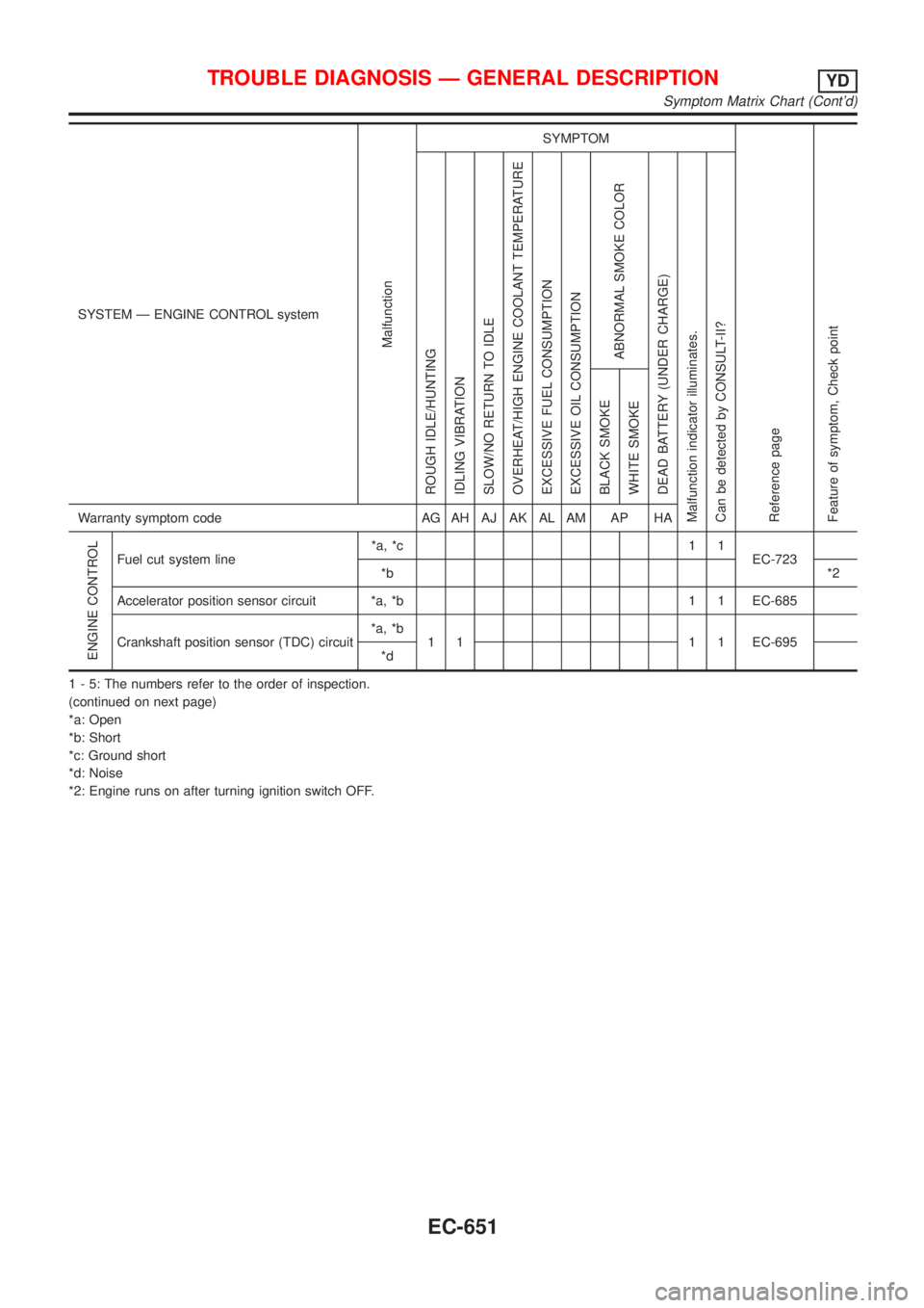
SYSTEM Ð ENGINE CONTROL system
Malfunction
SYMPTOM
Reference page
Feature of symptom, Check pointROUGH IDLE/HUNTING
IDLING VIBRATION
SLOW/NO RETURN TO IDLE
OVERHEAT/HIGH ENGINE COOLANT TEMPERATURE
EXCESSIVE FUEL CONSUMPTION
EXCESSIVE OIL CONSUMPTION
ABNORMAL SMOKE COLOR
DEAD BATTERY (UNDER CHARGE)
Malfunction indicator illuminates.
Can be detected by CONSULT-II?BLACK SMOKE
WHITE SMOKEWarranty symptom code AG AH AJ AK AL AM AP HA
ENGINE CONTROL
Fuel cut system line*a, *c 1 1
EC-723
*b*2
Accelerator position sensor circuit *a, *b 1 1 EC-685
Crankshaft position sensor (TDC) circuit*a, *b
1 1 1 1 EC-695
*d
1 - 5: The numbers refer to the order of inspection.
(continued on next page)
*a: Open
*b: Short
*c: Ground short
*d: Noise
*2: Engine runs on after turning ignition switch OFF.
TROUBLE DIAGNOSIS Ð GENERAL DESCRIPTIONYD
Symptom Matrix Chart (Cont'd)
EC-651
Page 1377 of 2898
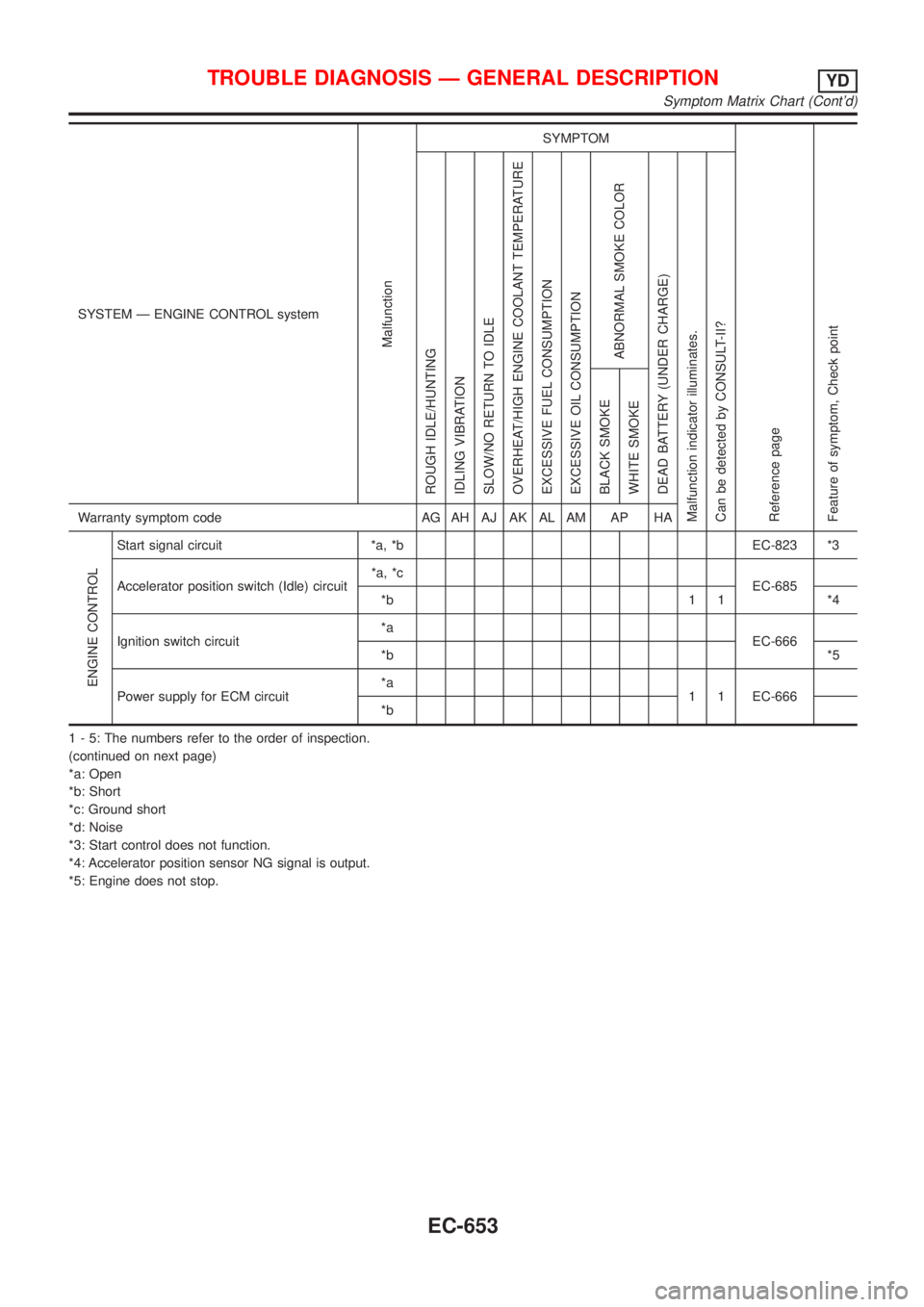
SYSTEM Ð ENGINE CONTROL system
Malfunction
SYMPTOM
Reference page
Feature of symptom, Check pointROUGH IDLE/HUNTING
IDLING VIBRATION
SLOW/NO RETURN TO IDLE
OVERHEAT/HIGH ENGINE COOLANT TEMPERATURE
EXCESSIVE FUEL CONSUMPTION
EXCESSIVE OIL CONSUMPTION
ABNORMAL SMOKE COLOR
DEAD BATTERY (UNDER CHARGE)
Malfunction indicator illuminates.
Can be detected by CONSULT-II?BLACK SMOKE
WHITE SMOKEWarranty symptom code AG AH AJ AK AL AM AP HA
ENGINE CONTROL
Start signal circuit *a, *b EC-823 *3
Accelerator position switch (Idle) circuit*a, *c
EC-685
*b 1 1 *4
Ignition switch circuit*a
EC-666
*b*5
Power supply for ECM circuit*a
1 1 EC-666
*b
1 - 5: The numbers refer to the order of inspection.
(continued on next page)
*a: Open
*b: Short
*c: Ground short
*d: Noise
*3: Start control does not function.
*4: Accelerator position sensor NG signal is output.
*5: Engine does not stop.
TROUBLE DIAGNOSIS Ð GENERAL DESCRIPTIONYD
Symptom Matrix Chart (Cont'd)
EC-653