low oil pressure NISSAN ALMERA N15 1995 User Guide
[x] Cancel search | Manufacturer: NISSAN, Model Year: 1995, Model line: ALMERA N15, Model: NISSAN ALMERA N15 1995Pages: 1701, PDF Size: 82.27 MB
Page 510 of 1701
![NISSAN ALMERA N15 1995 User Guide WARNINGLAMPSANDBUZZER
Warning Lamps/Schematic
>-
[[
W
f-
f-
<I:
CD
w
(f)
:J
l.L
UG
NATS
SECURITY
INDICATOR
NATSIMMU
ABS ABS
CONTROL
UNIT
OIL OILPRESSURE SWITCH
FUEL
FUELTANKGAUGE UNIT
WAS](/img/5/57349/w960_57349-509.png "NISSAN ALMERA N15 1995 User Guide WARNINGLAMPSANDBUZZER
Warning Lamps/Schematic
>-
[[
W
f-
f-
<I:
CD
w
(f)
:J
l.L
UG
NATS
SECURITY
INDICATOR
NATSIMMU
ABS ABS
CONTROL
UNIT
OIL OILPRESSURE SWITCH
FUEL
FUELTANKGAUGE UNIT
WAS")
WARNINGLAMPSANDBUZZER
Warning Lamps/Schematic
>-
[[
W
f-
f-
CD
w
(f)
:J
l.L
UG
NATS
SECURITY
INDICATOR
NATSIMMU
ABS ABS
CONTROL
UNIT
OIL OILPRESSURE SWITCH
FUEL
FUELTANKGAUGE UNIT
WASHER
WASHERFLUIDLEVELSWITCH
DOOR
FRONTDOORSWITCH
(Driver's side)
FRONT DOORSWITCH
(Passenger side)
REAR ODOR SWITCH LH
ALTERNATOR PARKING
BRAKESWITCH
FUEL FILTER SWITCH
=
BRAKE
FLUIDLEVEL SWITCH
REAR
ODORSWITCH RH
=
WARNING
BUZZER
UNIT
=
ECM (ECCS
CONTROL
MODULE)
ECM
(ENGINE
CONTROL
MODULE)
I
U
f- W
H (f)
3:f-
:J
(f)[[
l.L
Zf-
O(f)
H
f-L
HO
Z
BELT
C!JZ
HO
BRAKE
Q)
(I)
D.
rl
0
Q)
L
D
::J
0
W
E
L
C
0
ro
""-
D
Q)
(I)
(f)
rl
Q)
ro
D
D
'M
C
0
rl
ro
E
ro
L
~
Q) Q)
.....
u
C C
(I)
ro
.M
Q)
.M
ro
::J
.0
OJ
C
OJ
.M
c
.M
C
rl
U
Q)
OJ
Q)
ro
L
+'
C
L
0
ro
Q) Q) Q)
.....
""-
I
C C
(I)
GLOW
.M
rl
.
M
::J
.....
L
rl
Q)
rl
0
0
(I)
0
Q)
0
(I)
Q)
(I)
L
u
D
ro
.M
ro
0
x
I
C!J
0
C!J
l.L
W
lD
MALFUNCTION
@@~@@@
INDICATOR
AIRBAG
AIRBAG
DIAGNOSIS
SENSOR
UNIT
HEL082
EL-138
Page 519 of 1701

WARNINGLAMPSANDBUZZER
Warning Lamps/Wiring Diagram-WARN -
(Cont'd)
WITHOUT TACHOMETER
EL-WARN-09
FUELTANK
GAUGE UNIT
LOW (818)
HIGH
r.n
n
~ 888
B
i.Jl
FUEL
:
LHDmodels
@:
RHOmodels
~
G/R
I
1>
G/R ~ G/R~
1c!J1
@
1$1
(@
G/R G/R
~O~
I
G/R
m
OIL
LOW PRESSURE
SWITCH
HI~H-- ~
OIL
~
P/L
I
~01>
P
IL
f'UCi"\
P/L
f'UCi"\
~~ ~~
III7FII IlJdjl
T"' ~
'9F
(El0n
P/L P/L
t...oJ>
I
P/L~
c!J1illI
~(E202)
P/L
m
FUSE
Referto
8LOCK EL-POWER.
(J/8)
~
MALFUNCTION INDICATOR
~
ORIL
I
ORIL
Illii'n\
1i1'9il~
~@
ORIL
ORIL
0
24
LEO
RECM (ECCS
- CONTROL
MODULE) (Refer to
EC-MIL.)
ill)
P
;
NATS
SECULITY
INDICATOR
~
4=Jl
OR
OR
IFh
INO LAMP NATSIMMU
OUTPUT (Referto
EL-NATS.)
@>
L- __ --'
~-------------------------------~
~~@
5 6j819iO 1112W
Refer
tolast page •
(Foldout page).
CHID
(E10!)
ill)
IIIII~
128
~~@
l21U091V 65 W ~(E202)
rn::rn:rz::tm
8
([j])
<:lliTI)
GY
HEL079
EL-147
Page 721 of 1701
CONTENTS(Cont'd.)
CONSULT Reference ValueinData Monitor
Mode 74
Major Sensor Reference GraphinData
Monitor Mode 76
ECM Terminals andReference Value 78
TROUBLE DIAGNOSIS FORPOWER SUPPLY 88
Main Power Supply andGround Circuit.. 88
TROUBLE DIAGNOSIS FORDTC11 94
Camshaft PositionSensor(CMPS) 94
TROUBLE DIAGNOSIS FORDTC
12 101
Mass AirFlow Sensor (MAFS) 101
TROUBLE DIAGNOSIS FORDTC
13 108
Engine Coolant Temperature Sensor(ECTS) 108
TROUBLE DIAGNOSIS FORDTC
21 113
Ignition Signal 113
TROUBLE DIAGNOSIS FORDTC
34 119
Knock Sensor (KS) 119
TROUBLE DIAGNOSIS FORDTC
41 124
Intake AirTemperature Sensor(IATS) 124
TROUBLE DIAGNOSIS FORNON-DETECTABLE
ITEMS , '"
.128
Throttle Position Sensor 128
Vehicle SpeedSensor (VSS) 133
Start Signal 138
Injector 141
Fuel Pump 145
Idle AirControl Valve(IACV) -Auxiliary Air
Control (AAC)Valve 150
Cooling FanControl 156
Power Steering OilPressure Switch 169
Park/Neutral PositionSwitch 173
EVAP Canister PurgeControl Solenoid Valve179
EGR Valve andEVAP Canister PurgeControl
Solenoid Valve 183
Heated Oxygen Sensor(H02S) 189
Oxygen Sensor(02S) 194
Valve Timing Control (VTC) 198
IACV-FICD SolenoidValve 204
Electrical LoadSignal 211
Torque Converter ClutchSolenoid Valve 219
MIL
&
Data LinkConnectors 223
SR
ENGINE ANDEMISSION CONTROL OVERALL
SYSTE M
226
Circuit Diagram 226
System Diagram 227
ECCS Component PartsLocation 228
Vacuum HoseDrawing 231
System Chart... 232
ENGINE
ANDEMISSION BASICCONTROL
SYSTEM DESCRiPTION
233
Multipart FuelInjection (MFI)System 233
Distributor Ignition
(01)
System 235
Air Conditioning CutControl 236
Fuel CutControl (atnoload
&
high engine
speed) 237
EVAPORATIVE EMISSIONSYSTEM
238
Description 238
Inspection 238
POSITIVE CRANKCASE VENTILATION
240
Description 240
Inspection 240
BASIC SERVICE
PROCEDURE 241
Fuel Pressure Release 241
Fuel Pressure Check 241
Fuel Pressure Regulator Check 242
Injector Removal andInstallation 242
Idle Speed/Ignition Timing/IdleMixtureRatio
Adjustment 243
ON-BOARD DIAGNOSTIC SYSTEMDESCRIPTION ..250
Malfunction IndicatorLamp(MIL) 250
CONSULT 254
TROUBLE DIAGNOSIS -General Description
264
Introduction 264
Work Flow 265
Description forWork Flow 266
Diagnostic Worksheet 267
Diagnostic TroubleCode(DTC) Chart 268
Fail-Safe Chart 270
Basic Inspection 271
Symptom MatrixChart. 274
CONSULT Reference ValueinData Monitor
Mode 277
Major Sensor Reference GraphinData
Monitor Mode 279
ECM"Terminals andReference Value 281
TROUBLE DIAGNOSIS FORPOWER SUPPLY
286
Main Power Supply andGround Circuit.. 286
TROUBLE DIAGNOSIS FORDTC
11 289
Camshaft PositionSensor(CMPS) 289
TROUBLE DIAGNOSIS FORDTC
12 293
Mass AirFlow Sensor (MAFS) 293
TROUBLE DIAGNOSIS FORDTC
13 297
Engine Coolant Temperature Sensor(ECTS) 297
TROUBLE DIAGNOSIS FORDTC
21 301
Ignition Signal 301
TROUBLE DIAGNOSIS FORDTC
34 306
Knock Sensor (KS) 306
Page 722 of 1701
CONTENTS(Cont'd.)
TROUBLE DIAGNOSIS FORDTC
43 309
Throttle Position Sensor 309
TROUBLE DIAGNOSIS FORNON-DETECTABLE
ITEMS
314
Vehicle SpeedSensor (VSS) 314
Start Signal 317
Exhaust GasRecirculation (EGR)Valveand
EVAP Canister PurgeControl 319
Injector 324
Fuel Pump 327
Idle AirControl Valve(IACV)-Air Regulator 332
Idle AirControl Valve(IACV) -Auxiliary Air
Control (AAC)Valve :335
Idle AirControl Valve(IACV)-FICD Solenoid
Valve '"339
Cooling FanControl 343
Power Steering OilPressure Switch 354
Park/Neutral PositionSwitch 357
Heated Oxygen Sensor(H02S) 362
Torque
Converter
ClutchSolenoid Valve 367
Malfunction IndicatorLamp(MIL)
&
Data Link
Connector (DLC)forCONSULT 370
CD
INJECTION SYSTEM
371
VE.TYPE INJECTION PUMP
372
Removal 372
Installation 373
Adjustment 374
INJECTION NOZZLE
376
Removal andInstallation 376
Disassembly 376
Inspection 377
Cleaning 377
Assembly 378
Test andAdjustment 379
FUEL
SYSTEM CHECK
381
Priming PumpCheck 381
Fuel CutSolenoid Valve 381
CRANKCASE VENTILATION SYSTEM
382
Ventilation Hose 382
ENGINE ANDEMISSION CONTROLOVERALL
SYSTEM
383
Component PartsLocation 383
System Diagram 384
Circuit Diagram ,385
System Chart. 386
TROUBLE DIAGNOSES
387
ECM Terminals andReference Values 387
Quick-glow System 390
Partial LoadAdvance (PLA)Control 399
Cooling FanControl 404
Air Conditioner CutControl 413
Fuel CutControl 416
GA
SERVICE DATAANDSPECIFICATIONS
(505).417
General Specifications 417
Inspection andAdjustment.. 417
SR
SERVICE DATAANDSPECIFICATIONS
(505).418
General Specifications 418
Inspection andAdjustment.. .418
CD
SERVICE DATAANDSPECIFICATIONS
(505).419
VE-type Injection Pump 419
Injection Nozzle 419
•
When youread wiring diagrams:
• Read GIsection, "HOWTOREAD WIRING DIAGRAMS" .
• See Elsection, "POWER SUPPLYROUTING" forpower distribution circuit.
When youperform troublediagnoses, readGIsection, "HOWTOFOllOW FLOWCHART INTROU-
BLE DIAGNOSES" and"HOW TOPERFORM EFFICIENT DIAGNOSIS FORANELECTRICAL INCIDENT".
Page 736 of 1701
ENGINEANDEMISSION CONTROLOVERALLSYSTEM
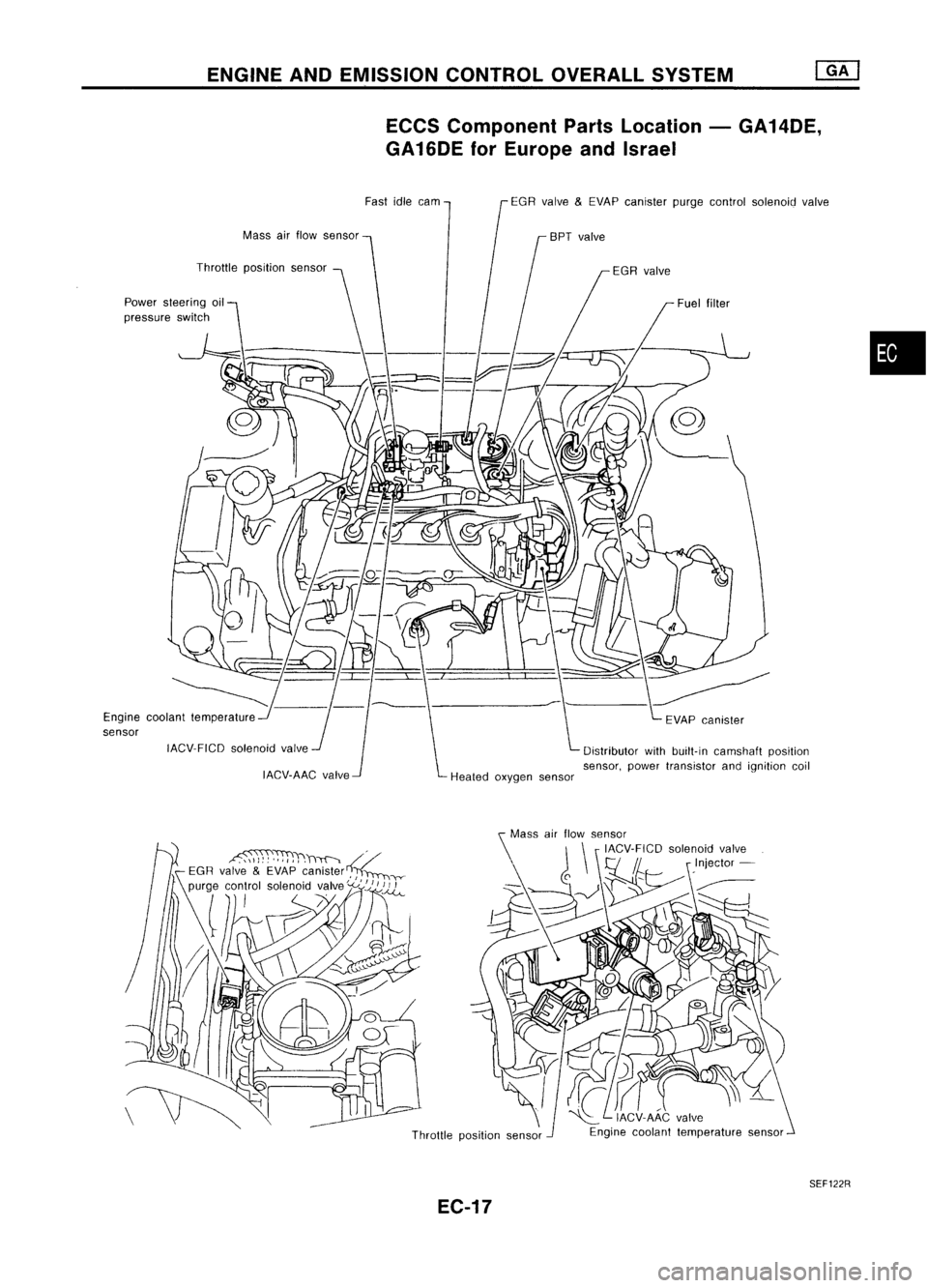
ECCS Component PartsLocation -GA14DE,
GA 16DE forEurope andIsrael
Mass airflow sensor
Throttle positionsensor
Power steering oil
pressure switch
Engine coolant temperature
sensor
IACV-FICDsolenoidvalve
IACV-AAC valveFast
idlecam EGRvalve
&
EVAP canister purgecontrol solenoid valve
Distributor withbuilt-in camshaft position
sensor, powertransistor andignition coil
•
Throttle positionsensor
SEF122R
EC-17
Page 742 of 1701

ENGINEANDEMISSION BASICCONTROL SYSTEMDESCRIPTION
System Chart
I
Camshaft positionsensor
'1
Fuel
injection
&
mixture
ratio control Injectors
Knock sensor
Distributorignitionsystem Powertransistor
Mass airflow sensor
Engine coolant temperature
sensor
Ignition switch Idle
aircontrol system
Fuel pump control
*4
IACV-AAC valve(WithFICD
solenoid valve)
Fuel pump relay
•
'5
Throttle
positionsensor
Neutral positionllnhibitor
switch
Air conditioner switch ECM
(ECCS
control
module)
2
Oxygen sensormonitor
&
On-board diagnostic system
5
Torque converter clutchcan-
cel solenoid valvecontrol
(A/T models) Malfunction
indicatorlamp
(On theinstrument panel)
Torque converter clutchsole-
noid valve
VTC solenoid valve
*6
Air
conditioner relays
Cooling
fanrelay
EVAP canister purgecontrol
solenoid valve
Cooling
fancontrol
Air conditioner cutcontrol
during acceleration
Valve timing control
EVAP canister purgecontrol
7
6
Power
steering oilpressure
switch Battery
voltage
Intake airtemperature sensor
*3
I
Vehicle speedsensor
*2
I
Oxygen sensor
8
'8
Electrical load
• Rear defogger switch
• Lighting switch EGR
&
EVAP canister purge
control EGR
valve
&
EVAP canister
purge control solenoid valve
*1: Except forEurope andIsrael
*2: Heated oxygen sensor(ForEurope andIsrael, andAustralia A/Tmodels)
Oxygen sensor(Except forEurope andIsrael, andAustralia A/Tmodels)
*3: For Australia
*4: IACV-AAC valveandIACV-FICD solenoidvalve(ForEurope andIsrael)
IACV-AAC valve(withFICDsolenoid valve)(Except forEurope andIsrael)
'5: Except forEurope
*6: GA16DE exceptforEurope andIsrael
*7: GA16DE MITmodels exceptforEurope, IsraelandAustralia
*8: For Europe andIsrael andAustralia, andGA15DE MITmodels
EC-23
Page 743 of 1701
ENGINEANDEMISSION BASICCONTROL SYSTEMDESCRIPTION
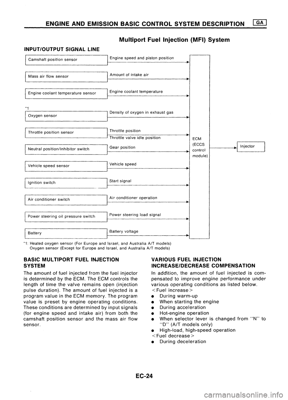
Multipart FuelInjection (MFI)System
INPUT/OUTPUT SIGNALLINE
Camshaft positionsensor
Mass airflow sensor
Engine coolant temperature sensor
*1
Oxygen sensor
Throttle position sensor
Neutral position/Inhibitor switch
Vehicle speedsensor
~gnition switch
Air conditioner switch
Power steering oilpressure switch
Battery Engine
speedandpiston position
Amount ofintake air
Engine coolant temperature
Density ofoxygen inexhaust gas
Throttle position
Throttle valveidleposition
Gear position
Vehicle speed
Start signal
Air conditioner operation
Power steering loadsignal
Battery voltage ECM
(ECCS
control module) Injector
*1: Heated oxygen sensor(ForEurope andIsrael, andAustralia A/Tmodels)
Oxygen sensor(Except forEurope andIsrael, andAustralia A/Tmodels)
BASIC MULTIPORT FUELINJECTION
SYSTEM
The amount offuel injected fromthefuel injector
is determined bythe ECM. TheECM controls the
length oftime thevalve remains open(injection
pulse duration). Theamount offuel injected isa
program valueinthe ECM memory. Theprogram
value ispreset byengine operating conditions.
These conditions aredetermined byinput signals
(for engine speedandintake air)from boththe
camshaft positionsensorandthemass airflow
sensor.
VARIOUS
FUELINJECTION
INCREASE/DECREASE COMPENSATION
In addition, theamount offuel injected iscom-
pensated toimprove engineperformance under
various operating conditions aslisted below.
<
Fuel increase>
• During warm-up
• When starting theengine
• During acceleration
• Hot-engine operation
• When selector leverischanged from"N"to
"D"
(AfT
models only)
• High-load, high-speed operation
<
Fuel decrease>
• During deceleration
EC-24
Page 754 of 1701

BASICSERVICE PROCEDURE
Idle Speedllgnition TiminglldleMixtureRatio
Adjustment
PREPARATION
• Make surethatthefollowing partsarein
good order.
(1) Battery
(2) Ignition system
(3) Engine oiland coolant levels
(4) Fuses
(5) ECM harness connector
(6) Vacuum hoses
(7) Airintake system
(Oil filler cap,oillevel gauge, etc.)
(8) Fuel pressure
(9)' Engine compression
(10) Throttle valve
(11) EGR valve operation -For Europe and
Israel andAustralia, andGA15DE M/Tmod-
els
Overall inspection sequence
INSPECTION
(12)
Evaporative emissionsystem
• On models equipped withairconditioner,
checks shouldbecarried outwhile theair
conditioner is"OFF".
• On models equipped withautomatic
transaxle, whenchecking idlespeed, ignition
timing andmixture ratio,checks shouldbe
carried outwhile shiftlever isin
"N"
position.
• When measuring
"CO"
percentage, insert
probe morethan40cm (15.7 in)into tailpipe .•
• Turn offheadlamps, heaterblower, rear
defogger.
• Keep frontwheels pointed straight ahead.
• Make thecheck afterthecooling fanhas
stopped.
Perform diagnostic testmode
1/
(Self-diagnostic results).
Check
&
adjust ignition timing.
Check
&
adjust idlespeed. NG
Repair orreplace.
Check oxygen sensor*1 function.
OK
Check
oxygen sensor*1 har-
ness.
Check CO%.
NG
NG
Repair orreplace harness.
OK Replace oxygensensor*1.
INSPECTION END Check
emission controlparts NGCheck oxygen sensor*1 function. OK
and repair orreplace ifneces-
sary.
*1: Heated oxygen sensor(ForEurope andIsrael, andAustralia AfTmodels)
Oxygen sensor(Except forEurope andIsrael, andAustralia AfTmodels)
EC-35
Page 768 of 1701
ON-BOARDDIAGNOSTIC SYSTEMDESCRIPTION
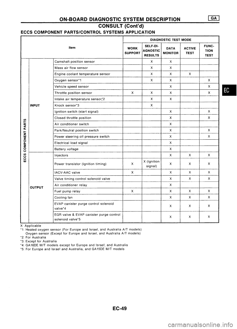
CONSULT (Cont'd)
ECCS COMPONENT PARTS/CONTROL SYSTEMSAPPLICATION
DIAGNOSTICTESTMODE
Item WORKSELF-DI-
ACTIVEFUNC-
DATA
SUPPORT AGNOSTIC
MONITOR TION
TEST
RESULTS TEST
Camshaft positionsensor
X
X
Mass airflow sensor
X
X
Engine coolant temperature sensor
X
X X
Oxygen sensor'1
X
X X
Vehicle speedsensor
XX
Throttle positionsensor
XX
X X
Intake airtemperature sensor.'2
X
X
INPUT
Knock
sensor'3
X
Ignition switch(startsignal)
XX
I/)
Closed
throttle position
X
X
l-
ll:
Airconditioner switch
X
<
~
Park/Neutralpositionswitch
X
X
I-
Z
UJ
Powersteering oilpressure switch
XX
z
0
Electricalloadsignal
X
~
:E
0
Batteryvoltage
X
u
I/)
Injectors
XX
X
u
u
UJ
X(Ignition
Power transistor (Ignitiontiming) X X
XX
signal)
IACV-AAC valve X
XX
X
Valve timing control solenoid valve XX
X
OUTPUT
Air
conditioner relay
X
Fuel pump relay XX
XX
Cooling fan XX
X
EVAP canister purgecontrol solenoid
XX X
valve'4
EGR valve
&
EVAP canister purgecontrol
XX
X
solenoid valve'5
X: Applicable
'1: Heated oxygen sensor(ForEurope andIsrael, andAustralia AITmodels)
Oxygen sensor(Except forEurope andIsrael, andAustralia AITmodels)
'2: For Australia
'3: Except forAustralia
'4: GA16DE
MIT
models exceptforEurope andIsrael, andAustralia
'5: For Europe andIsrael andAustralia, andGA15DE
MIT
models
EC-49
•
Page 770 of 1701
ON-BOARDDIAGNOSTIC SYSTEMDESCRIPTION
CONSULT (ConI'd)
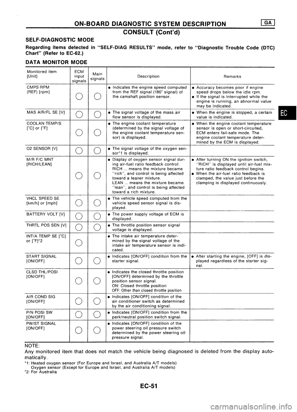
SELF-DIAGNOSTIC MODE
Regarding itemsdetected in"SELF-DIAG RESULTS"mode,referto"Diagnostic TroubleCode(DTC)
Chart" (RefertoEC-62.)
DATA MONITOR MODE
Monitored item ECM
Main
[Unit] input
signals Description
Remarks
signals
CMPS.RPM •Indicates theengine speedcomputed •Accuracy becomespoorifengine
(REF) [rpm]
00
from
theREF signal (180'signal) of
speeddropsbelow theidle rpm.
the camshaft positionsensor.
•Ifthe signal isinterrupted whilethe
engine isrunning, anabnormal value
may beindicated .
MAS AIR/FL SE[V]
0 0
•
The signal voltage ofthe mass air
•When theengine isstopped, acertain
flow sensor isdisplayed .
valueisindicated.
COOLAN TEMP/S
•The engine coolant temperature •When theengine coolant temperature
['C] or['F]
00
(determined
bythe signal voltage of
sensorisopen orshort-circuited,
the engine coolant temperature sen-ECMenters fail-safe mode.The
sor) isdisplayed.
enginecoolant temperature deter-
mined bythe ECM isdisplayed .
02 SENSOR [V]
00
•
The signal voltage ofthe oxygen sen-
sor*1 isdisplayed .
M/R F/CMNT •
Display ofoxygen sensorsignaldur-
•After turning ONthe ignition switch,
[RICH/LEAN] ingair-fuel ratiofeedback control: "RICH"isdisplayed untilair-fuel mix-
RICH ...means themixture became
tureratio feedback controlbegins.
0 0
"rich",
andcontrol isbeing affected •When theair-fuel ratiofeedback is
toward aleaner mixture.
clamped,thevalue justbefore the
LEAN ...means themixture became clampingisdisplayed continuously.
"lean", andcontrol isbeing affected
toward arich mixture .
VHCL SPEED SE
00
•
The vehicle speedcomputed fromthe
[km/h] or[mph] vehicle
speedsensor signalisdis-
played .
BATTERY VOLT[V]
0 0
•
The power supply voltage ofECM is
displayed .
THRTL POSSEN[V]
0 0
•
The throttle position sensorsignal
voltage isdisplayed.
INT/A TEMP SE['C] •The intake airtemperature deter-
or ['F]*2
0
mined
bythe signal voltage ofthe
intake airtemperature sensorisindi-
cated .
START SIGNAL
00
•
Indicates [ON/OFF] conditionfromthe•After starting theengine, [OFF]isdis-
[ON/OFF] startersignal. playedregardless ofthe starter sig-
nal.
CLSD THLIPOSI •Indicates theclosed throttle position
[ON/OFF]
00
[ON/OFF]
determined bythe throttle
position sensorsignal.
ON: Closed throttle position
OFF: Other thanclosed throttle position
AIR COND SIG
00
•
Indicates [ON/OFF] conditionofthe
[ON/OFF] air
conditioner switchasdetermined
by the airconditioning signal.
PIN POSI SW
00
•
Indicates [ON/OFF] conditionfromthe
[ON/OFF] park/neutralpositionswitchsignal.
PW/ST SIGNAL •
Indicates [ON/OFF] conditionofthe
[ON/OFF]
00
power
steering oilpressure switch
determined bythe power steering oil
pressure signal.
NOTE:
Any monitored itemthatdoes notmatch thevehicle beingdiagnosed isdeleted fromthedisplay auto-
matically.
*1: Heated oxygen sensor(ForEurope andIsrael, andAustralia A/Tmodels)
Oxygen sensor(Except forEurope andIsrael, andAustralia A/Tmodels)
*2: For Australia
EC-51
•