Abs NISSAN ALMERA N15 1995 Owner's Manual
[x] Cancel search | Manufacturer: NISSAN, Model Year: 1995, Model line: ALMERA N15, Model: NISSAN ALMERA N15 1995Pages: 1701, PDF Size: 82.27 MB
Page 315 of 1701
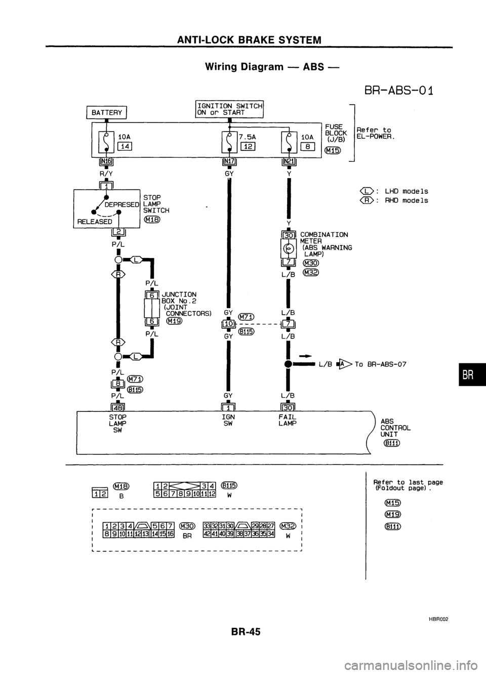
ANTI-LOCKBRAKESYSTEM
Wiring Diagram -ABS -
BR-ABS-01
•
ABS
CONTROL
UNIT
(B111)
LHDmodels
@:
RHOmodels
Refer
to
EL-POWER.
FUSE
BLOCK
(JIB)
~
GY
ffi
IGN
SW
Y
I~I COMBINATION
METER
(ABS WARNING
LAMP)
~@
LIB
@
I
GY
$-------$
GY (~) LIB
I-
e-
LIB~ ToBR-ABS-O?
I
LIB
13-0
I
FAIL
LAMP
IGNITION
SWITCH
ON orSTART
STOP
DEPRESED LAMP
SWITCH
RELEASED ~
~
P!L
•
~:I
P!L
rn~
I
JUNCTION
BOX
NO.2
(JOINT
CONNECTORS)
1!:i=!J~
PIL
~~
•
PIL
lelIl
9F'~
P!L
14-81
STOP
LAMP
SW
Fa~
l..1..@
B ~~(B115)
5 6
TI1910
1112 W
Refer
tolast page
(Foldout page).
~---------------------------------,
L ~
HBR002
BR-45
Page 316 of 1701
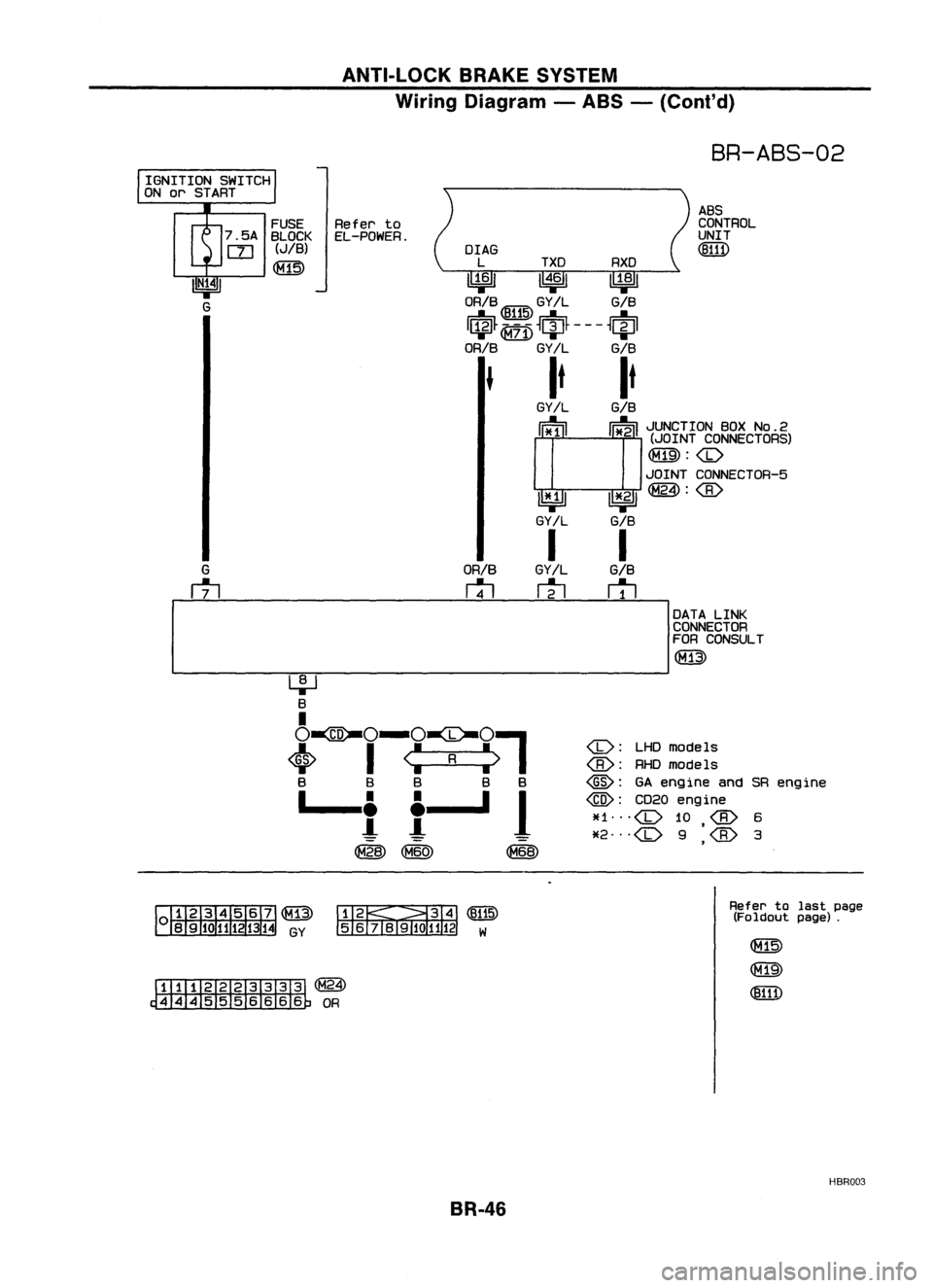
ANTI-LOCKBRAKESYSTEM
Wiring Diagram -ABS -(Coni' d)
BR-ABS-02
ABS
CONTROL
UNIT
(!ID1)
OrAG
L TXD RXD
~ 1~61~
ORIB ~ GY!L GIB
I$~ ~
~ciJ~ ---
~~I
ORIB
GY/L GIB
It It
GY!L
GIB
cr
l I~
i~MO~o~?ic~g~)
~:
JOINT CONNECTOR-5
~ 1*.21~:
GY/L GIB
I I
GY/L
GIB
m
r1l
ORIB
rtl
FUSE
Referto
7 .5A BLOCK EL-POWER.
rn
(JIB)
~
IGNITION
SWITCH
ON orSTART
I
DATALINK
CONNECTOR
FOR CONSULT
(M13)
-----------------------
<0:
LHDmodels
@:
GAengine andSRengine
@:
CD20engine
~f1
<0
10
*2
<0
9
'
,
~~(~)
56j819101112 W
~(~24)
~OR
Refer
tolast page
(Foldout page).
HBR003
BR-46
Page 317 of 1701
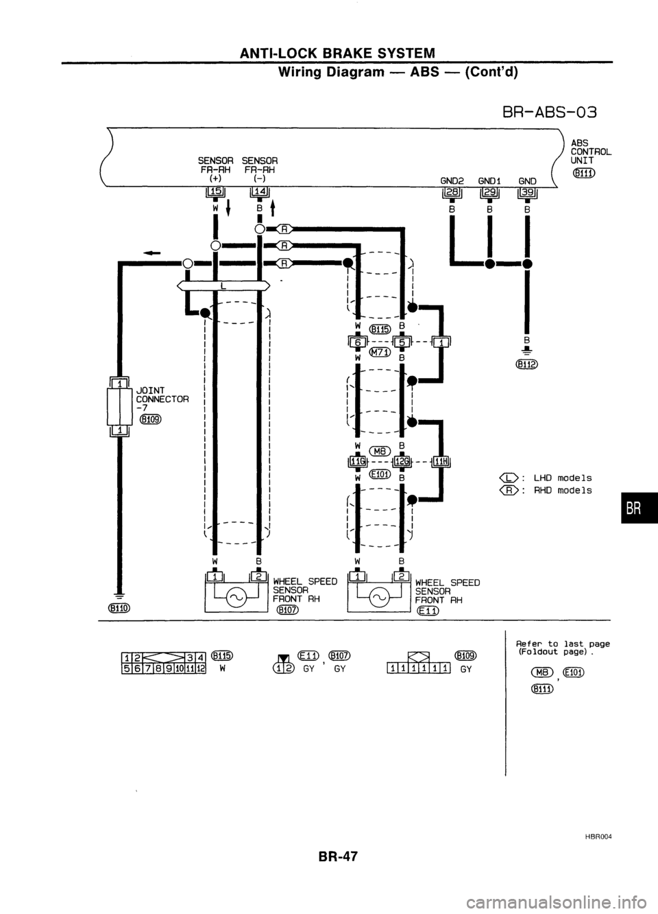
ANTI-LOCKBRAKESYSTEM
Wiring Diagram -ABS -(Cont'd)
BR-ABS-03
•
ABS
CONTROL
UNIT
LHO models
RHO models
(jJ:
(8):
GN02
GNO1 GNO
12.81 12.911
3•
9
1
B BB
Ll-l
I
----
)
I
1
I
1
----
']
W@1IDB .
$---$-]1
W
@)
8
-----
(,
-
_.
1 -- I
I I
I I
l.... •
l~t~~8}j~f
-]1
W «(1Q"n B
-----
r-- _
I I
I 1
1 1
l....
'J
R
R
~
..
1
1
I
I
I ....
l
SENSOR
FR-RH
H
~
B
t
I
o
,. 1
1
1
I
I
I
I
1
I
I
1
I
J 1
1
I
1
1
I
I
1
1
1
1
1
I
1
I ....
t
-
rn
JOINT
CONNECTOR
-7
(B109)
1
WB
~ WHEELSPEED
SENSOR
rv
FRONTRH
(1llQj)
W
B
M
WHEELSPEED
SENSOR
rv
FRONTRH
(E 11)
&~(BIT5)
5 6TII9ID 1112W ..In
em),
@ill)
<..!J.g)
GYGY
~(Eli[9)
IIlIITl.IIillJ
GY
Refer
tolast page
(Foldout page).
HBR004
BR-47
Page 318 of 1701
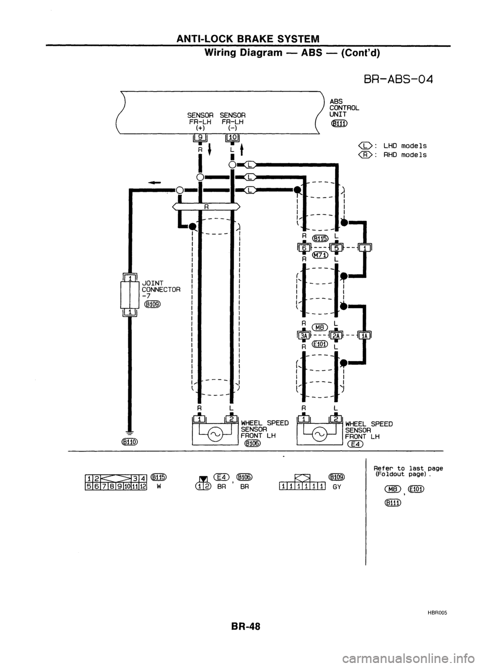
ANTI-LOCKBRAKESYSTEM
Wiring Diagram -ABS -(Cont'd)
BR-ABS-04
ASS
CONTROL
SENSOR UNIT
FR-LH
~
H
~
models
L
t
•
@:
RHOmodels
0
L
L
-
-
-
--
-ec
,.
)
I
I
I
I
I
I
I
----
1--
']
)
t
----
I
R~ L
I
I
$---$J
I
I
R
1
1
-
-
--
I
mJOINT
I
I'-- --
!
I
1
CONNECTOR
I
I
I
-7
I
1
I
(B109)
l--•
1
-----
A@L ]
I$f---J$-J
R
(ffi1)
L
-----
(,
.
I I
-
---
1
I
I
I
--
,I
II
t
)
(
)
-----
-----
R L R
L
M
.>'EELSPEED
M
WHEEL
SPEED
SENSOR SENSOR
-
rvFRONTLH
rvFRONTLH
(eUO)
(8106)
@
~~(@
56 iBl91
@,(~)
(tig)
SR SR
BR-48 ~(B109)
illIIIIIIIIIl
GY
Refer
tolast page
(Foldout page).
HBR005
Page 319 of 1701
ANTI-LOCKBRAKESYSTEM
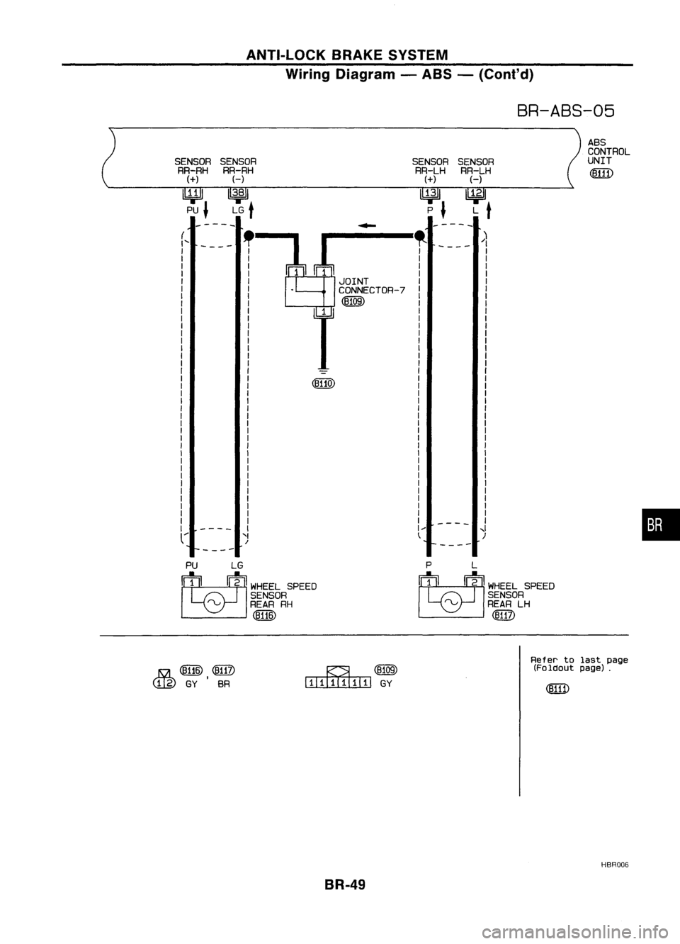
Wiring Diagram -ABS -(Conl'd)
BR-ABS-05
-----
-----
A8S
CONTROL
UNIT
SENSOR
RR-LH
H
~ L
t
"
----
/)
I
I
I
I
I
I
I
I
I
SENSOR
RR-LH
(+)
lY;ll
P
J
r-:l~!
I
JOINT
I .
CONNECTOR-7
I
@QID
r
(8110)
SENSOR
RR-RH
H
1
3•8
1
LG
t
(
....
SENSOR
RR-RH
(+)
~ PU
J
----
'I
/
I
1
1
I
I
I
I
I
I
I
I
I
I
I
I
I
,I
)
•
PU LG
M
WHEELSPEED
SENSOR
rv REARRH
(!W)
P
L
M
WHEELSPEED
SENSOR
rv
REARLH
(ffi?)
15a
([UID ,
@TI)
C!J.g)
GYSR ~(8109)
l:TIIillIIIIIJ
GY
Refer
tolast page
(Foldout page).
HBR006
BR-49
Page 320 of 1701
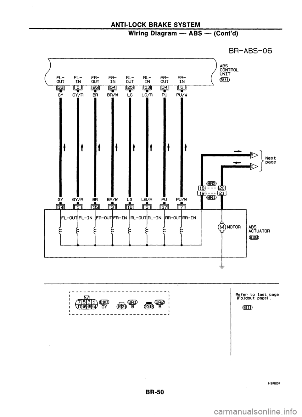
ANTI-LOCKBRAKESYSTEM
Wiring Diagram -ABS -(Coni' d)
BR-ABS-06
ABS
CONTROL
UNIT
FL- FL-FR-
FR- RL-
RL-RR-
RR-
~
OUT INOUT
INOUT
INOUT IN
1
3';'
IbiJ
1
2•6
1
1
5•4
1
1
2';'
1
5•3
1
1
3•4
1
~
GY GY/R
BRBR/W
LGLG/R
PUPU/W
t tt
t tt tt
-
B
}Next
-
page
C
@
18 --- 20
19 --- 21
GY GY/R
BRBR/W
LGLG/R PUPU/W
~
nf4ll
m ~
rTI
wf6n
rrtll
Iff7il
~
FL -OUT FL-IN FR-OUT FR-IN RL-OUT RL-IN RR-OUT RR-IN
M
MOTOR ABS
ACTUATOR
(fJ103)
=
r-------------------------,
I
~~ ~@:
~ B~ B
I
I
L
~
BR-50
Refer
tolast page
(Foldout page).
HBRDD?
Page 321 of 1701

ANTI-LOCKBRAKESYSTEM
Wiring Diagram -ABS -(ConI' d)
SR-ASS-07
I
BAT.ERY
I
rJ:~~30A
LtJw LtJm
Refer
to
EL-POWER. SOLENOID
VALVE
RELAY
CONTROL
(-)
1
3:
I
LG/R MOTOR
RELAY
MONITOR
~
L
MOTOR
RELAY
CONTROL
(+)
~
Y
MOTOR
RELAY
CONTROL
(-)
4=U
G/R
ABS
CONTROL
UNIT
~
BR Y
tt
J
t
.
Precedin
g{ ~
-
page
-
B
rg.~~, ~
L/B~
tttt
•
t
BR LIBLG/R
LY
Y G/R
ffi
n=fo]
rh
m
n=f3n
m
rrf1iJ
*
-----<
@>
@ @
@)
SOLENOID
I:
~
)
~
MOTOR
VALVE
I
?
RELAY
RELAY
(lli)
I@
@
@>
I@
~
ABS
RELAY •
BOX :.
UQ)
~)
~----------------------~
I
: UQ)
I
(411'3)
GY
I
~~
~B
Refer
tolast page
(Foldout page).
~----------------------~
BR-51
HBRDDa
Page 322 of 1701
TROUBLEDIAGNOSES
Contents
How toPerform TroubleDiagnoses forQuick andAccurate Repair SR-52
Self-diagnosis SR-53
CONSULT BR-58
CONSULT Inspection Procedure BR-59
Component PartsandHarness Connector Location BR-64
Preliminary Check BR-65
Ground CircuitCheck BR-66
Circuit Diagram forQuick Pinpoint Check BR-67
Diagnostic Procedure1Warning lampdoes notcome on BR-68
Diagnostic Procedure2Warning lampstays on BR-69
Diagnostic Procedure3ABS actuator solenoid valve BR-72
Diagnostic Procedure 4Wheel sensor orrotor BR-74
Diagnostic Procedure5Motor relayormotor BR-76
Diagnostic Procedure6Solenoid valverelay BR-79
Diagnostic Procedure7Power supply BR-81
Diagnostic Procedure 8Control unit BR-82
Diagnostic Procedure9Pedal vibration andnoise BR-82
Diagnostic Procedure10Long stopping distance BR-83
Diagnostic Procedure11Unexpected pedalaction BR-83
Diagnostic Procedure12ABS does notwork BR-84
Diagnostic Procedure13ABS works frequently BR-84
Electrical Component Inspection BR-85
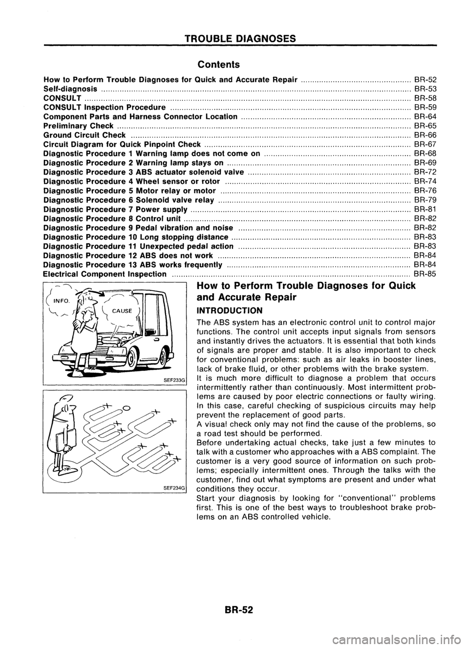
How toPerform TroubleDiagnoses forQuick
and Accurate Repair
INTRODUCTION
The ABS system hasanelectronic controlunittocontrol major
functions. Thecontrol unitaccepts inputsignals fromsensors
and instantly drivestheactuators. Itis essential thatboth kinds
of signals areproper andstable. Itis also important tocheck
for conventional problems:suchasair leaks inbooster lines,
lack ofbrake fluid,orother problems withthebrake system.
SEF233G
Itis much moredifficult todiagnose aproblem thatoccurs
intermittently ratherthancontinuously. Mostintermittent prob-
lems arecaused bypoor electric connections orfaulty wiring.
In this case, careful checking ofsuspicious circuitsmayhelp
prevent thereplacement ofgood parts.
A visual checkonlymaynotfind thecause ofthe problems, so
a road testshould beperformed.
Before undertaking actualchecks, takejustafew minutes to
talk with acustomer whoapproaches withaABS complaint. The
customer isavery good source ofinformation onsuch prob-
lems; especially intermittent ones.Through thetalks withthe
customer, findoutwhat symptoms arepresent andunder what
SEF234G
conditions theyoccur.
Start yourdiagnosis bylooking for"conventional" problems
first. Thisisone ofthe best ways totroubleshoot brakeprob-
lems onanABS controlled vehicle.
BR-52
Page 323 of 1701
.=J
MPH
-~s::~
~~
___ --- warnin:1
TROUBLE
DIAGNOSES
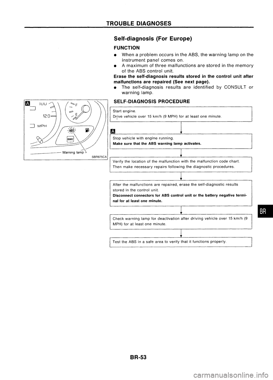
Self-diagnosis (ForEurope)
FUNCTION
• When aproblem occursinthe ABS, thewarning lamponthe
instrument panelcomes on.
• Amaximum ofthree malfunctions arestored inthe memory
of the ABS control unit.
Erase theself-diagnosis resultsstoredinthe control unitafter
malfunctions arerepaired (Seenextpage).
• The self-diagnosis resultsareidentified byCONSULT or
warning lamp.
SELF-DIAGNOSIS PROCEDURE
Start engine.
Dr.ive vehicle over15km/h (9MPH) foratleast oneminute .
Stop vehicle withengine running.
Make surethaitheASS warning lampactivates.
SBR875CA
Verifythelocation ofthe malfunction withthemalfunction codechart.
Then make necessary repairsfollowing thediagnostic procedures.
After themalfunctions arerepaired, erasetheself-diagnostic results
stored inthe control unit.
Disconnect connectors forASS control unitorthe battery negative termi-
nal foratleast oneminute.
Check warning lampfordeactivation afterdriving vehicle over15km/h (9
MPH) foratleast oneminute.
Test theASS inasafe area toverify thatitfunctions properly.
BR-53
•
Page 325 of 1701

TROUBLEDIAGNOSES
Self-diagnosis (ForEurope) (Cont'd)
MALFUNCTION CODE/SYMPTOM CHART
Code No.
Malfunctioningpart Diagnostic
procedure
(No. ofwarning lampflashes)
45
Actuator
frontleftoutlet solenoid valve
3
46
Actuator
frontleftinlet solenoid valve
3
41
Actuator
frontrightoutlet solenoid valve
3
42
Actuator
frontrightinletsolenoid valve
3
51
Actuator
rearright outlet solenoid valve
3
52
Actuatorrearright inletsolenoid valve
3
55
Actuator
rearleftoutlet solenoid valve
3
56
Actuator
rearleftinlet solenoid valve
3
25
Frontleftsensor (open-circuit)
4
26
Front
leftsensor (short-circuit)
4
21
Frontrightsensor (open-circuit)
4
22
Front
rightsensor (short-circuit)
4
35
Rearleftsensor (open-circuit)
4
36
Rear
leftsensor (short-circuit)
4
31
Rearrightsensor (open-circuit)
4
32
Rearrightsensor (short-circuit)
4
18
Sensorrotor
4
61
Actuatormotorormotor relay
5
63
Solenoidvalverelay
6
57
Powersupply (Lowvoltage)
7
71
Controlunit
8
Control unitpower supply circuit
Warning lampstays onwhen igni-Warning
lampbulbcircuit
tion switch isturned on Control
unitorcontrol unitconnector
2
Solenoid valverelaystuck
Power supply forsolenoid valverelaycoil
Warning lampstays on,during
Controlunit
-
self-diagnosis
Warning lampdoesnotcome onFuse, warning lampbulborwarning lampcircuit
1
when ignition switchisturned onControl unit
Warning lampdoes notcome on
Control unit
during self-diagnosis
-
Pedal vibration andnoise
-
9
Long stopping distance
-
10
Unexpected pedalaction
-
11
ABS does notwork
-
12
ABS works frequently
-
13
BR-55
•