coolant NISSAN ALMERA N15 1995 Owner's Manual
[x] Cancel search | Manufacturer: NISSAN, Model Year: 1995, Model line: ALMERA N15, Model: NISSAN ALMERA N15 1995Pages: 1701, PDF Size: 82.27 MB
Page 762 of 1701

BASICSERVICE PROCEDURE []KJ
Idle Speed/Ignition Timing/IdleMixtureRatio
Adjustment (Cont'd)
@
Connect oxygensensorharness connector tooxygen
sensor.
Check fuelpressure regulator.
(See page EC-33.)
.
Check massairflow sensor anditscircuit.
(See page EC-107.)
Check injector anditscircuit.
(See page EC-141.)
Clean orreplace ifnecessary.
Check engine coolant temperature sensoranditscir-
cuit. (See page EC-112.)
Check ECMfunction* bysubstituting anotherknown
good ECM.
*.ECM maybethe caus
but this israrely thece
of aproblem,
ase.
•
EC-43
Page 765 of 1701
ON-BOARDDIAGNOSTIC SYSTEMDESCRIPTION @KJ
Malfunction Indicatorlamp(Mil)(Cont'd)
DIAGNOSTIC TESTMODE I-BULB CHECK
In this mode, theMALFUNCTION INDICATORLAMPonthe instrument panelshould stayON.Ifitremains
OFF, check thebulb. Refer toEL section ("WARNING LAMPSANDCHIME") orsee EC-223.
DIAGNOSTIC TESTMODE I-MALFUNCTION WARNING
MALFUNCTION INDICATORLAMP
ON
OFF Condition
Engine coolant temperature sensorcircuitmalfunction oroverheating isdetected, or
the ECM's CPUismalfunctioning.
No malfunction.
• These Diagnostic TroubleCodeNumbers areclarified inDiagnostic TestMode II(SELF-DIAGNOS-
TIC RESULTS).
DIAGNOSTIC TESTMODE II-SELF-DIAGNOSTIC RESULTS
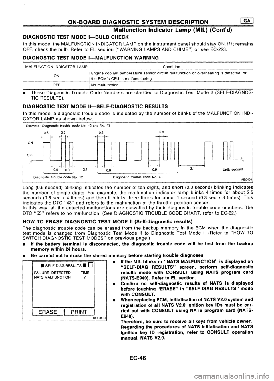
In this mode, adiagnostic troublecodeisindicated bythe number ofblinks ofthe MALFUNCTION INDI-
CATOR LAMPasshown below.
Example: Diagnostic troublecodeNo.12and No.43
ON
0.6
03
111-'1
0.6
II
0.3
OFF
j
~
~~ -I.
--.1
-4--1--
Q9 O~ 21 OB Q9
'--------v----' '--------v------~
Diagnostic troublecodeNo.12 DiagnostictroublecodeNo.43
2.1
Unit:second
AEC490
• SELF-DIAG RESULTS.
0
FAILURE DETECTED TIME
NATS MALFUNCTION
0
I
ERASE
II
PRINT
I
SEF288Q
Long
(0.6second) blinkingindicates thenumber often digits, andshort (0.3second) blinkingindicates
the number ofsingle digits. Forexample, themalfunction indicatorlampblinks 4times forabout 2.5
seconds (0.6secx4 times) andthen itblinks threetimes forabout 1second (0.3secx3 times). This
indicates theDTC "43" andrefers tothe malfunction ofthe throttle position sensor.
In this way, allthe detected malfunctions areclassified bytheir diagnostic troublecodenumbers. The
DTC "55" refers tono malfunction. (SeeDIAGNOSTIC TROUBLECODECHART, refertoEC-62.)
HOW TOERASE DIAGNOSTIC TESTMODE II(Self-diagnostic results)
The diagnostic troublecodecanbeerased fromthebackup memory inthe ECM when thediagnostic
test mode ischanged fromDiagnostic TestMode IIto Diagnostic TestMode
I.
(Refer to"HOW TO
SWITCH DIAGNOSTIC TESTMODES" onprevious page.)
• Ifthe battery terminal isdisconnected, thediagnostic troublecodewillbelost from thebackup
memory within24hours.
• Becareful nottoerase thestored memory before
startin~
troublediagnoses.
• If
the MIL blinks or"NATS MALFUNCTION" isdisplayed on
"SELF-OIAG RESULTS"screen,perform self-diagnostic
results modewithCONSULT usingNATS program card
(NATS-E940). RefertoEL section.
• Confirm noself-diagnostic resultsofNATS isdisplayed
before touching "ERASE" in"SELF-DIAG RESULTS"mode
with CONSULT.
• When replacing ECM,initialisation ofNATS V2.0system and
registration ofall NATS V2.0ignition key10smust becar-
ried outwith CONSULT usingNATS program card(NATS-
E940).
Therefore, besure toreceive allkeys from vehicle owner.
Regarding theprocedures ofNATS initialisation andNATS
ignition key10registration, refertoCONSULT operation
manual, NATS V2.0.
EC-46
Page 766 of 1701
ON-BOARDDIAGNOSTIC SYSTEMDESCRIPTION
[QKJ
Malfunction Indicatorlamp(Mil)(Cont'd)
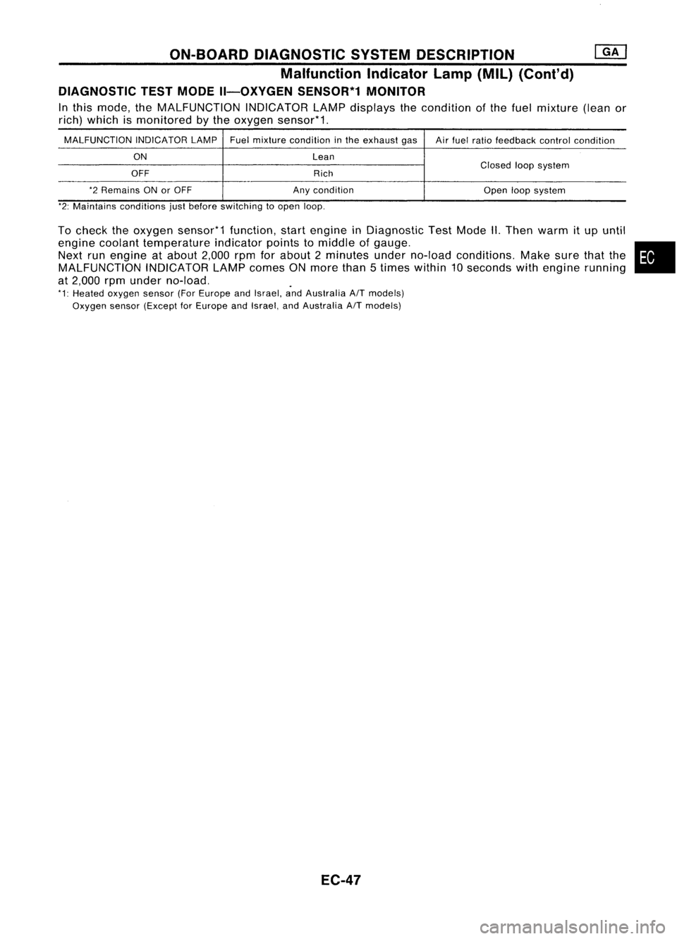
DIAGNOSTIC TESTMODE II-OXYGEN SENSOR*1MONITOR
In this mode, theMALFUNCTION INDICATORLAMPdisplays thecondition ofthe fuel mixture (leanor
rich) which ismonitored bythe oxygen sensor*1.
MALFUNCTION INDICATORLAMPFuelmixture condition inthe exhaust gas
Airfuel ratio feedback controlcondition
ON Lean
OFF RichClosed
loopsystem
*2 Remains ONorOFF Anycondition
Openloopsystem
*2: Maintains conditions justbefore switching toopen loop.
To check theoxygen sensor*1 function,startengine inDiagnostic TestMode II.Then warm itup until
engine coolant temperature indicatorpointstomiddle ofgauge. •
Next runengine atabout 2,000rpmforabout 2minutes underno-load conditions. Makesurethatthe
MALFUNCTION INDICATORLAMPcomes ONmore than5times within 10seconds withengine running
at 2,000 rpmunder no-load. .
*1: Heated oxygen sensor(ForEurope andIsrael, andAustralia
AfT
models)
Oxygen sensor(Except forEurope andIsrael, andAustralia
AfT
models)
EC-47
Page 768 of 1701
ON-BOARDDIAGNOSTIC SYSTEMDESCRIPTION
CONSULT (Cont'd)
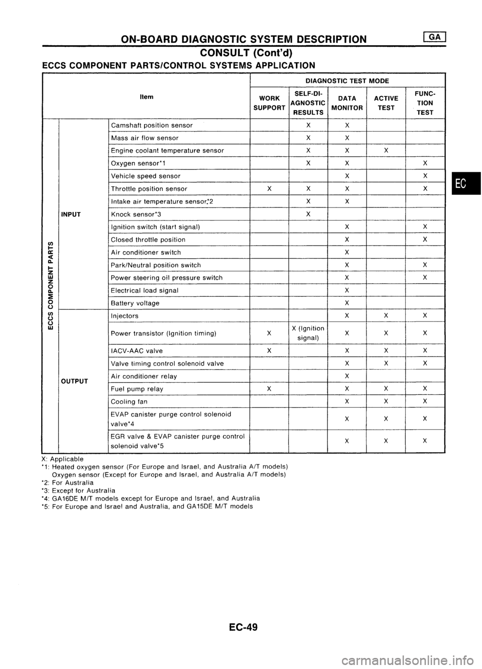
ECCS COMPONENT PARTS/CONTROL SYSTEMSAPPLICATION
DIAGNOSTICTESTMODE
Item WORKSELF-DI-
ACTIVEFUNC-
DATA
SUPPORT AGNOSTIC
MONITOR TION
TEST
RESULTS TEST
Camshaft positionsensor
X
X
Mass airflow sensor
X
X
Engine coolant temperature sensor
X
X X
Oxygen sensor'1
X
X X
Vehicle speedsensor
XX
Throttle positionsensor
XX
X X
Intake airtemperature sensor.'2
X
X
INPUT
Knock
sensor'3
X
Ignition switch(startsignal)
XX
I/)
Closed
throttle position
X
X
l-
ll:
Airconditioner switch
X
<
~
Park/Neutralpositionswitch
X
X
I-
Z
UJ
Powersteering oilpressure switch
XX
z
0
Electricalloadsignal
X
~
:E
0
Batteryvoltage
X
u
I/)
Injectors
XX
X
u
u
UJ
X(Ignition
Power transistor (Ignitiontiming) X X
XX
signal)
IACV-AAC valve X
XX
X
Valve timing control solenoid valve XX
X
OUTPUT
Air
conditioner relay
X
Fuel pump relay XX
XX
Cooling fan XX
X
EVAP canister purgecontrol solenoid
XX X
valve'4
EGR valve
&
EVAP canister purgecontrol
XX
X
solenoid valve'5
X: Applicable
'1: Heated oxygen sensor(ForEurope andIsrael, andAustralia AITmodels)
Oxygen sensor(Except forEurope andIsrael, andAustralia AITmodels)
'2: For Australia
'3: Except forAustralia
'4: GA16DE
MIT
models exceptforEurope andIsrael, andAustralia
'5: For Europe andIsrael andAustralia, andGA15DE
MIT
models
EC-49
•
Page 770 of 1701
ON-BOARDDIAGNOSTIC SYSTEMDESCRIPTION
CONSULT (ConI'd)
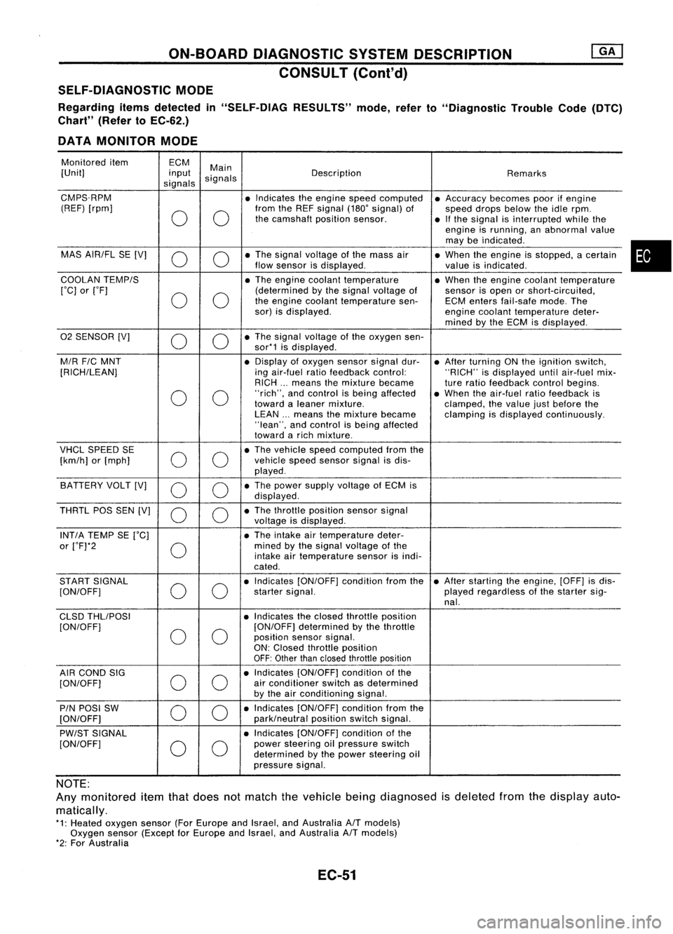
SELF-DIAGNOSTIC MODE
Regarding itemsdetected in"SELF-DIAG RESULTS"mode,referto"Diagnostic TroubleCode(DTC)
Chart" (RefertoEC-62.)
DATA MONITOR MODE
Monitored item ECM
Main
[Unit] input
signals Description
Remarks
signals
CMPS.RPM •Indicates theengine speedcomputed •Accuracy becomespoorifengine
(REF) [rpm]
00
from
theREF signal (180'signal) of
speeddropsbelow theidle rpm.
the camshaft positionsensor.
•Ifthe signal isinterrupted whilethe
engine isrunning, anabnormal value
may beindicated .
MAS AIR/FL SE[V]
0 0
•
The signal voltage ofthe mass air
•When theengine isstopped, acertain
flow sensor isdisplayed .
valueisindicated.
COOLAN TEMP/S
•The engine coolant temperature •When theengine coolant temperature
['C] or['F]
00
(determined
bythe signal voltage of
sensorisopen orshort-circuited,
the engine coolant temperature sen-ECMenters fail-safe mode.The
sor) isdisplayed.
enginecoolant temperature deter-
mined bythe ECM isdisplayed .
02 SENSOR [V]
00
•
The signal voltage ofthe oxygen sen-
sor*1 isdisplayed .
M/R F/CMNT •
Display ofoxygen sensorsignaldur-
•After turning ONthe ignition switch,
[RICH/LEAN] ingair-fuel ratiofeedback control: "RICH"isdisplayed untilair-fuel mix-
RICH ...means themixture became
tureratio feedback controlbegins.
0 0
"rich",
andcontrol isbeing affected •When theair-fuel ratiofeedback is
toward aleaner mixture.
clamped,thevalue justbefore the
LEAN ...means themixture became clampingisdisplayed continuously.
"lean", andcontrol isbeing affected
toward arich mixture .
VHCL SPEED SE
00
•
The vehicle speedcomputed fromthe
[km/h] or[mph] vehicle
speedsensor signalisdis-
played .
BATTERY VOLT[V]
0 0
•
The power supply voltage ofECM is
displayed .
THRTL POSSEN[V]
0 0
•
The throttle position sensorsignal
voltage isdisplayed.
INT/A TEMP SE['C] •The intake airtemperature deter-
or ['F]*2
0
mined
bythe signal voltage ofthe
intake airtemperature sensorisindi-
cated .
START SIGNAL
00
•
Indicates [ON/OFF] conditionfromthe•After starting theengine, [OFF]isdis-
[ON/OFF] startersignal. playedregardless ofthe starter sig-
nal.
CLSD THLIPOSI •Indicates theclosed throttle position
[ON/OFF]
00
[ON/OFF]
determined bythe throttle
position sensorsignal.
ON: Closed throttle position
OFF: Other thanclosed throttle position
AIR COND SIG
00
•
Indicates [ON/OFF] conditionofthe
[ON/OFF] air
conditioner switchasdetermined
by the airconditioning signal.
PIN POSI SW
00
•
Indicates [ON/OFF] conditionfromthe
[ON/OFF] park/neutralpositionswitchsignal.
PW/ST SIGNAL •
Indicates [ON/OFF] conditionofthe
[ON/OFF]
00
power
steering oilpressure switch
determined bythe power steering oil
pressure signal.
NOTE:
Any monitored itemthatdoes notmatch thevehicle beingdiagnosed isdeleted fromthedisplay auto-
matically.
*1: Heated oxygen sensor(ForEurope andIsrael, andAustralia A/Tmodels)
Oxygen sensor(Except forEurope andIsrael, andAustralia A/Tmodels)
*2: For Australia
EC-51
•
Page 772 of 1701
ON-BOARDDIAGNOSTIC SYSTEMDESCRIPTION
CONSULT (Cont'd)
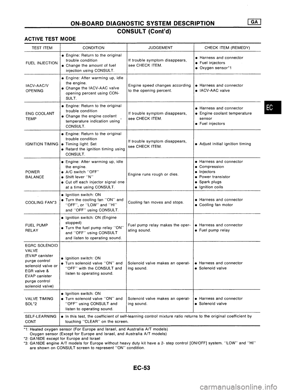
ACTIVE TESTMODE
TEST ITEM CONDITION JUDGEMENT
CHECKITEM(REMEDY)
• Engine: Returntothe original
•Harness andconnector
FUEL INJECTION trouble
condition If
trouble symptom disappears,
•Fuel injectors
• Change theamount offuel see
CHECK ITEM.
injection usingCONSULT . •
Oxygen sensor*1
• Engine: Afterwarming up,idle
IACV-AACIV the
engine.
Enginespeedchanges according •Harness andconnector
OPENING •
Change theIACV-AAC valve
tothe opening percent. •
IACV-AAC valve
opening percentusingCON-
SULT.
• Engine: Returntothe original
•Harness andconnector
ENG COOLANT trouble
condition
Iftrouble symptom disappears, •
Engine coolant temperature
TEMP •
Change theengine coolant
.
see CHECK ITEM. sensor
temperature indicationusing
•Fuel injectors
CONSULT.
• Engine: Returntothe original
trouble condition
Iftrouble symptom disappears,
IGNITION TIMING•
Timing light:Set •
Adjust initialignition timing
• Retard theignition timingusingsee
CHECK ITEM.
CONSULT .
• Engine: Afterwarming up,idle •
Harness andconnector
the engine. •
Compression
POWER •
A/C switch "OFF"
Enginerunsrough ordies . •
Injectors
BALANCE •
Shift lever "N" •
Power transistor
• Cut offeach injector signalone •
Spark plugs
at atime using CONSULT. •
Ignition coils
• Ignition switch:ON
COOLING FAN*3•
Turn thecooling fan"ON" and
Cooling fanmoves andstops. •
Harness andconnector
"OFF", or"LOW" and"HI" •
Cooling fanmotor
and "OFF" usingCONSULT .
• Ignition switch:ON(Engine
FUEL PUMP stopped)
Fuelpump relaymakes theoper- •Harness andconnector
• Turn thefuel pump relay"ON"
RELAY and"OFF" usingCONSULT ating
sound. •
Fuel pump relay
and listen tooperating sound.
EGRC SOLENOID
VALVE (EVAP canister
•Ignition switch:ON
purge control
•Turn solenoid valve"ON" and Solenoid
valvemakes anoperat- •
Harness andconnector
solenoid valveor
EGR valve
&
"OFF"
withtheCONSULT andingsound. •
Solenoid valve
EVAP canister listen
tooperating sound.
purge control
solenoid valve)
•Ignition switch:ON
VALVE TIMING •
Turn solenoid valve"ON" and Solenoid
valvemakes anoperat- •
Harness andconnector
SOL*2 "OFF"
usingCONSULT anding
sound. •
Solenoid valve
listen tooperating sound.
SELF-LEARNING •
Inthis test, thecoefficient ofself-learning controlmixture ratioreturns tothe original coefficient by
CONT touching
"CLEAR" onthe screen.
*1: Heated oxygen sensor(ForEurope andIsrael, andAustralia A/Tmodels)
Oxygen sensor(Except forEurope andIsrael, andAustralia A/Tmodels)
*2: GA16DE except forEurope andIsrael
*3: GA16DE engine A/Tmodels forEurope without heavydutykithave a2- step control [ON/OFF] system."LOW"and"HI"
are shown onCONSULT screentorepresent "ON"condition.
EC-53
•
Page 774 of 1701
ON-BOARDDIAGNOSTIC SYSTEMDESCRIPTION
CONSULT (Conl'd)
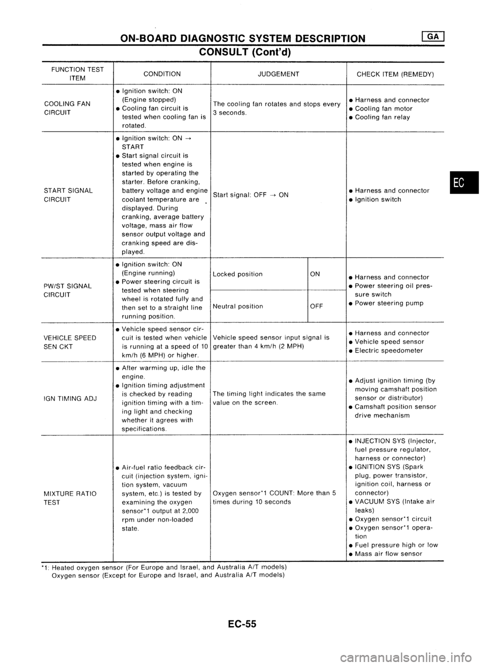
FUNCTION TEST
CONDITION JUDGEMENT
ITEM CHECK
ITEM(REMEDY)
• Ignition switch:ON
COOLING FAN (Engine
stopped)
Thecooling fanrotates andstops every •
Harness andconnector
CIRCUIT •
Cooling fancircuit is
3seconds. •
Cooling fanmotor
tested whencooling fanis
•Cooling fanrelay
rotated .
• Ignition switch:ON-.
START
• Start signal circuit is
tested whenengine is
started byoperating the
starter. Beforecranking,
START SIGNAL batteryvoltage andengine
Startsignal: OFF-.ON •
Harness andconnector
CIRCUIT coolanttemperature are •
Ignition switch
displayed. During
cranking, averagebattery
voltage, massairflow
sensor outputvoltage and
cranking speedaredis-
played .
• Ignition switch:ON
(Engine running)
Lockedposition ON
•Harness andconnector
PW/ST SIGNAL •
Power steering circuitis
•Power steering oilpres-
tested whensteering
CIRCUIT wheelisrotated fullyand sure
switch
then settoastraight lineNeutral
position OFF•
Power steering pump
running position.
• Vehicle speedsensor cir-
•Harness andconnector
VEHICLE SPEED cuit
istested whenvehicle Vehicle
speedsensor inputsignal is
•Vehicle speedsensor
SEN CKT is
running ataspeed of10 greater
than4km/h (2MPH)
•Electric speedometer
km/h (6MPH) orhigher .
• After warming up,idle the
engine. •Adjust ignition timing(by
• Ignition timingadjustment
movingcamshaft position
IGN TIMING ADJ is
checked byreading The
timing lightindicates thesame
sensorordistributor)
ignition timingwithatim- value
onthe screen.
•Camshaft positionsensor
ing light andchecking
drivemechanism
whether itagrees with
specifications.
•INJECTION SYS(Injector,
fuel pressure regulator,
harness orconnector)
• Air-fuel ratiofeedback cir- •
IGNITION SYS(Spark
cuit (injection system,igni- plug,
power transistor,
tion system, vacuum ignition
coil,harness or
MIXTURE RATIO system,
etc.)istested byOxygen
sensor'1 COUNT:Morethan5 connector)
TEST examining
theoxygen times
during 10seconds •
VACUUM SYS(Intake air
sensor'1 outputat2,000 leaks)
rpm under non-loaded •
Oxygen sensor'1 circuit
state. •
Oxygen sensor'1 opera-
tion
• Fuel pressure highorlow
• Mass airflow sensor
'1: Heated oxygen sensor(ForEurope andIsrael, andAustralia AITmodels)
Oxygen sensor(Except forEurope andIsrael, andAustralia
A/T
models)
EC-55
•
Page 781 of 1701
TROUBLEDIAGNOSIS -General Description
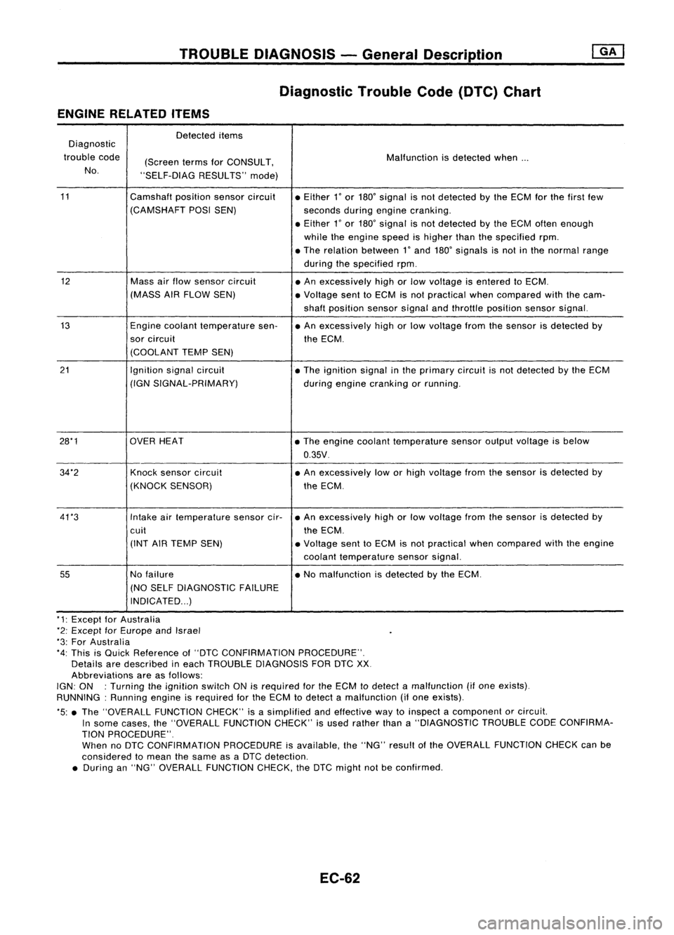
Diagnostic TroubleCode(DTC) Chart
ENGINE RELATED ITEMS
Detected items
Diagnostic
trouble code
(ScreentermsforCONSULT, Malfunction
isdetected when...
No. "SELF-DIAG RESULTS"mode)
11 Camshaftpositionsensorcircuit
•Either
l'
or 180' signal isnot detected bythe ECM forthe first few
(CAMSHAFT POSISEN)
secondsduringengine cranking .
• Either
l'
or 180' signal isnot detected bythe ECM often enough
while theengine speedishigher thanthespecified rpm.
• The relation between
l'
and 180' signals isnot inthe normal range
during thespecified rpm.
12 Massairflow sensor circuit
•An excessively highorlow voltage isentered toECM.
(MASS AIRFLOW SEN) •Voltage senttoECM isnot practical whencompared withthecam-
shaft position sensorsignalandthrottle position sensorsignal.
13 Enginecoolant temperature sen-•An excessively highorlow voltage fromthesensor isdetected by
sor circuit
theECM.
(COOLANT TEMPSEN)
21 Ignitionsignalcircuit
•The ignition signalinthe primary circuitisnot detected bythe ECM
(IGN SIGNAL-PRIMARY)
duringengine cranking orrunning .
28*1 OVERHEAT •The engine coolant temperature sensoroutputvoltage isbelow
0.35V .
34"2 Knocksensor circuit •An excessively loworhigh voltage fromthesensor isdetected by
(KNOCK SENSOR) theECM.
41 *3 Intakeairtemperature sensorcir-•An excessively highorlow voltage fromthesensor isdetected by
cuit theECM.
(INT AIRTEMP SEN) •Voltage senttoECM isnot practical whencompared withtheengine
coolant temperature sensorsignal.
55
Nofailure •No malfunction isdetected bythe ECM.
(NO SELF DIAGNOSTIC FAILURE
INDICATED ...)
"1: Except forAustralia
*2: Except forEurope andIsrael
"3: For Australia
*4: This isQuick Reference of"DTC CONFIRMATION PROCEDURE".
Details aredescribed ineach TROUBLE DIAGNOSIS FORDTCXX
Abbreviations areasfollows:
IGN: ON :Turning theignition switchONisrequired forthe ECM todetect amalfunction (ifone exists).
RUNNING: Runningengineisrequired forthe ECM todetect amalfunction (ifone exists).
*5: •The "OVERALL FUNCTIONCHECK"isasimplified andeffective waytoinspect acomponent orcircuit.
In some cases, the"OVERALL FUNCTIONCHECK"isused rather thana"DIAGNOSTIC TROUBLECODECONFIRMA-
TION PROCEDURE".
When noDTC CONFIRMATION PROCEDUREisavailable, the"NG" result ofthe OVERALL FUNCTION CHECKcanbe
considered tomean thesame asaDTC detection .
• During an"NG" OVERALL FUNCTION CHECK,theDTC might notbeconfirmed.
EC-62
Page 782 of 1701
TROUBLEDIAGNOSIS -General Description
mJ
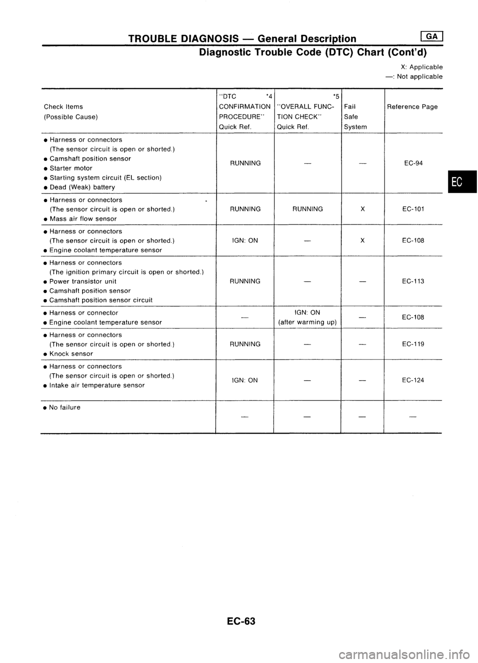
Diagnostic TroubleCode(DTC) Chart(Cont'd)
X:Applicable
-: Not applicable
"DTC *4
*5
Check Items CONFIRMATION
"OVERALLFUNC-Fail ReferencePage
(Possible Cause) PROCEDURE"
TIONCHECK" Safe
Quick Ref. QuickRef. System
• Harness orconnectors
(The sensor circuitisopen orshorted.)
• Camshaft positionsensor
RUNNING EC-94
-
-
• Starter motor
• Starting systemcircuit(ELsection)
• Dead (Weak) battery
• Harness orconnectors
.
(The sensor circuitisopen orshorted.) RUNNING
RUNNING
X
EC-101
• Mass airflow sensor
• Harness orconnectors
(The sensor circuitisopen orshorted.) IGN:ON
-
X
EC-108
• Engine coolant temperature sensor
• Harness orconnectors
(The ignition primary circuitisopen orshorted.)
• Power transistor unit RUNNING
-
-
EC-113
• Camshaft positionsensor
• Camshaft positionsensorcircuit
• Harness orconnector IGN:
ON
EC-108
- -
• Engine coolant temperature sensor (after
warming up)
• Harness orconnectors
(The sensor circuitisopen orshorted.) RUNNING
-
-
EC-119
• Knock sensor
• Harness orconnectors
(The sensor circuitisopen orshorted.)
IGN:ON
-
-
EC-124
• Intake airtemperature sensor
• No failure
----
EC-63
•
Page 783 of 1701
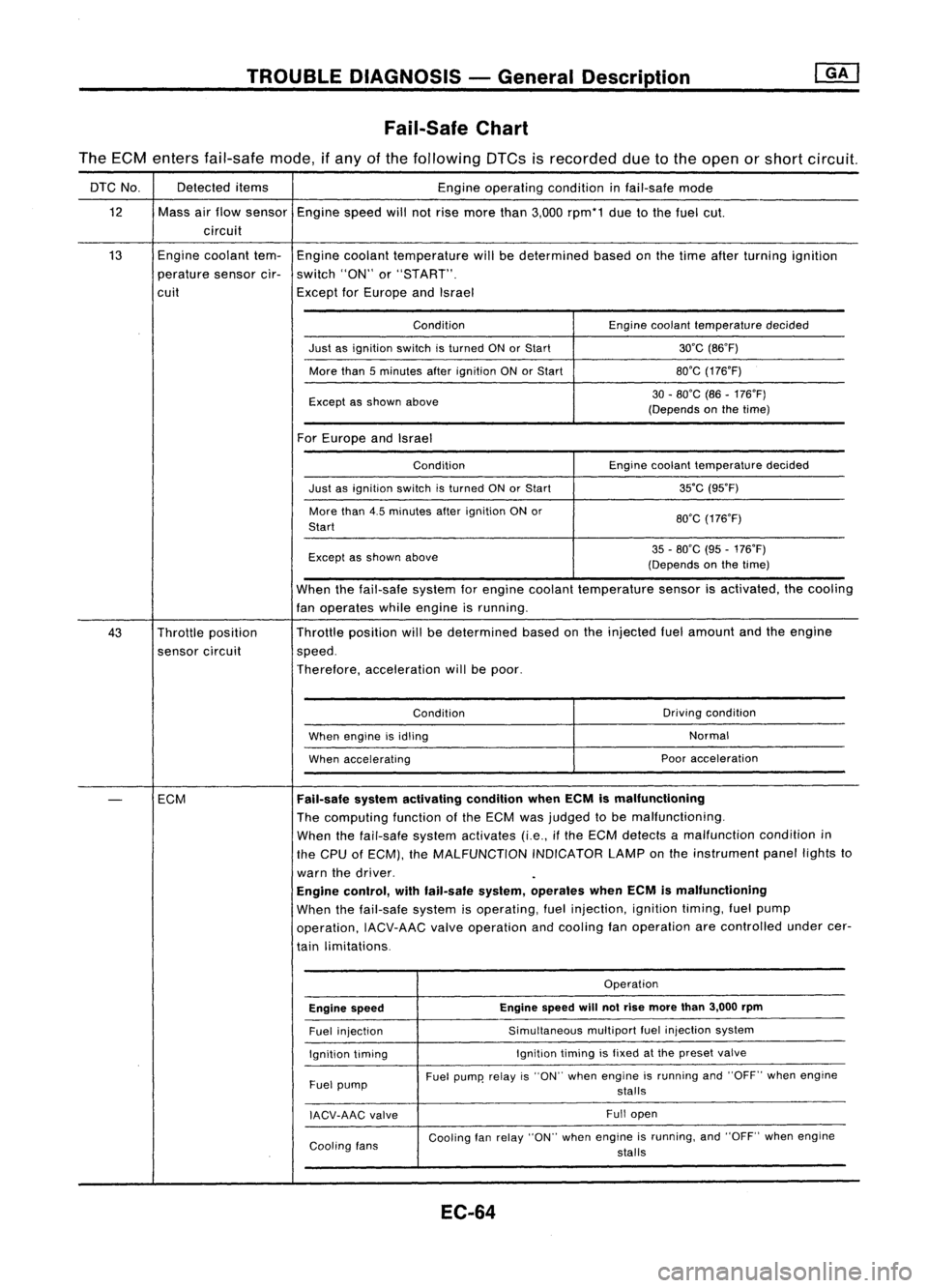
TROUBLEDIAGNOSIS -General Description
Fail-Safe Chart
The ECM enters fail-safe mode,ifany ofthe following DTCsisrecorded duetothe open orshort circuit.
DTC No. Detected
items
Engineoperating conditioninfail-safe mode
12 Massairflow sensor
Enginespeedwillnotrise more than3,000 rpm*1 duetothe fuel cut.
circuit
13 Engine
coolant tem-
Engine coolant temperature willbedetermined basedonthe time after turning ignition
perature sensorcir-switch "ON"or"START".
cuit ExceptforEurope andIsrael
Condition Enginecoolant temperature decided
Just asignition switchisturned ONorStart 30'C(B6'F)
More than5minutes afterignition ONorStart BO'G
(176'F)
Except asshown above 30
-BO'C (B6-176'F)
(Depends onthe time)
For Europe andIsrael
Condition Enginecoolant temperature decided
Just asignition switchisturned ONorStart 35'C
(95'F)
More than4.5minutes afterignition ONor
BO'G(176'F)
Start
Except asshown above 35
-BO'C (95-176'F)
(Depends onthe time)
When thefail-safe systemforengine coolant temperature sensorisactivated, thecooling
fan operates whileengine isrunning.
43 Throttle position Throttle
position willbedetermined basedonthe injected fuelamount andtheengine
sensor circuit speed.
Therefore, acceleration willbepoor.
Condition Driving
condition
When engine isidling Normal
When accelerating Poor
acceleration
-
ECM
Fail-safe
systemactivating conditionwhenECMismalfunctioning
The computing functionofthe ECM wasjudged tobe malfunctioning.
When thefail-safe systemactivates (i.e.,ifthe ECM detects amalfunction conditionin
the CPU ofECM), theMALFUNCTION INDICATORLAMPonthe instrument panellightsto
warn thedriver.
Engine control, withfail-safe system,operates whenECMismalfunctioning
When thefail-safe systemisoperating, fuelinjection, ignitiontiming,fuelpump
operation, IACV-AACvalveoperation andcooling fanoperation arecontrolled undercer-
tain limitations.
Operation
Engine speed Engine
speed
will
notrise more than3,000 rpm
Fuel injection Simultaneous
multipartfuelinjection system
Ignition timing Ignition
timingisfixed atthe preset valve
Fuel pump Fuel
pump' relayis"ON" when engine isrunning and"OFF" whenengine
stalls
IACV-AAG valve Full
open
Cooling fans Cooling
fanrelay "ON" whenengine isrunning, and"OFF" whenengine
stalls
EC-64