warning light NISSAN ALMERA N15 1995 Service Manual
[x] Cancel search | Manufacturer: NISSAN, Model Year: 1995, Model line: ALMERA N15, Model: NISSAN ALMERA N15 1995Pages: 1701, PDF Size: 82.27 MB
Page 308 of 1701
consists ofelectronic andhydraulic components. Itallows forcon-
trol ofbraking forcesothat locking ofthe wheels canbeavoided.
The ABS:
1) I")
ANTI-LOCKBRAKESYSTEM
Purpose
The Anti-Lock BrakeSystem (ABS)consists ofelectronic andhydraulic components. Itallows forcon-
trol ofbraking forcesothat locking ofthe wheels canbeavoided.
The ABS:
1) Improves propertracking performance throughsteering wheeloperation.
2) Eases obstacles tobe avoided throughsteering wheeloperation.
3) Improves vehiclestability bypreventing flatspins.
Operation
• When thevehicle speedisless than 10km/h (6MPH) thissystem doesnotwork.
• The Anti-Lock BrakeSystem (ABS)hasself-test capabilities. Thesystem turnsonthe ABS warning
light for1second afterturning theignition switchON.The system performs anothertestthefirst time
the vehicle reaches 6km/h (4MPH). Amechanical noisemaybeheard asthe ABS performs aself-
test. This isanormal partofthe self-test feature.Ifa malfunction isfound during thischeck, theABS
warning lightwillcome on.
• During ABSoperation, amechanical noisemaybeheard. Thisisanormal condition.
ABS Hydraulic Circuit
G)
Inletsolenoid valve
@
Outlet solenoid valve
@
Reservoir
@)
Pump
)(
@
@
Motor
@
Inletvalve
(J)
Outlet valve
@ Bypass checkvalve
BR-38 @
Check valve
@)
Damper
@
Gradient switch
SBR918C
Page 309 of 1701

ANTI-LOCKBRAKESYSTEM
System Components
Dual proportioning
valve
Rearwheel sensors
For LHD models, controlunit
is located onthe opposite side.
SBR048DB
Control unit
s::';o~'~W.
r
I .I
Tooth~ Sensorrotor
/ ~m~f onetooth
v:~-- System
Description
SENSOR
The sensor unitconsists ofagear-shaped sensorrotoranda
sensor element. Theelement contains abar magnet around
which acoil iswound. Thesensor isinstalled onthe back side
of the brake rotor.Sine-wave currentisgenerated bythe sen-
sor asthe wheel rotates. Thefrequency andvoltage increase(s) •
as the rotating speedincreases. :•
V: Induced electromotive force
SBR124B
SBR049DA CONTROL
UNIT
The control unitcomputes thewheel rotating speedbythe sig-
nal current sentfrom thesensor. Thenitsupplies aDC current
to the actuator solenoid valve.Italso controls ON-OFFopera-
tion ofthe valve relayandmotor relay.Ifany electrical malfunc-
tion should bedetected inthe system, thecontrol unitcauses
the warning lamptolight up.Inthis condition, theASS willbe
deactivated bythe control unit,andthevehicle's brakesystem
reverts tonormal operation.
BR-39
Page 338 of 1701

Warning lampdoes notcome onwhen ignition switchisturned
on.
c(
C/UNIT CONNECTOR
30
p~
15
SBR238D WARNING
LIGHTCIRCUIT CHECK
Che")
TROUBLEDIAGNOSES
Diagnostic Procedure1(Not self-diagnostic item)
Warning lampdoes notcome onwhen ignition switchisturned
on.
c(
C/UNIT CONNECTOR
30
p~
15
SBR238D WARNING
LIGHTCIRCUIT CHECK
Check 10Afuse ~forwarning lamp.
For fuse layout, refertoSR-4S.
OK
Check warning lampbulb.
NG
NG
Replace
fuse.
Replace bulb.
Ii) ASSrelay box6-pin
connector (bodyside)
~ 108
c(
C/UNIT CONNECTOR
P
I...a1
30~
15
l.41
Iv
OK
1. Install 10Afuse andbulb.
2. Disconnect connectors fromcontrol
unit and ASS relay box.
3. Check voltage between controlunit
connector terminal
@
and ground
after turning ignition switch"ON".
Battery voltage shouldexistafter
turning ignition switch
"ON".
OK
NG
Repair harness andcon-
nectors.
OK
Continuity
shouldexist.
•
Check continuity betweenASSrelay
box 6-pin connector (bodyside)and
control unitterminals.
\ ASS relay box
f~~~_
SBR239D
~i5
@ID
ASS relay box6-pin
connector (ASS relayboxside)
108
ASS
relay box
@)
unit
@
Ground
NG
Repair harness andcon-
nectors.
1. Remove solenoid valverelay.
2. Check continuity betweenASSrelay
SBR945CB
box6-pin connector (ASSrelaybox
side) andASS relay boxterminals.
ASS relay box ASS
relay box
connector terminals
@)\B
@e
Continuity shouldexist.
Note: Payattention totester polarity",
OK
SOLENOID VALVERELAYCHECK
Refer toSOLENOID VALVERELAY in
Electrical Components Inspection,
BR-8S.
OK
Go toDiagnostic Procedure7,BR-81.
NG
NG
Replace
ABSrelay box.
Replace solenoid valve
relay.
": Specifications mayvary depending onthe type oftester.
Before performing thisinspection, refertothe instrucllon manualofthe
tester.
BR-68
Page 374 of 1701

Front FogLamp Aiming Adjustment.. 101
Rear FogLamp/Wiring Diagram-R/FOG -102
Turn Signal andHazard Warning Lamps/
Schematic 106
Turn Signal andHazard Warning
Lamps/Wiring Diagram")
CONTENTS(Conl'd.)
Front FogLamp Aiming Adjustment.. 101
Rear FogLamp/Wiring Diagram-R/FOG -102
Turn Signal andHazard Warning Lamps/
Schematic 106
Turn Signal andHazard Warning
Lamps/Wiring Diagram-TURN - 107
Turn Signal andHazard Warning
Lamps/Trouble Diagnoses 113
Combination FlasherUnitCheck 113
Bulb Specifications 114
INTERIOR LAMP 115
Illumination/Schematic 115
Illumination/Wiring Diagram-ILL - 116
Interior, Spot,Trunk Room andLuggage
Room Lamps/Wiring Diagram-INT/L - 122
Bulb Specifications 126
METER ANDGAUGES 127
Combination Meter 127
Speedometer, Tachometer,Temp.andFuel
Gauges/Wiring Diagram-METER - 129
Inspection/Fuel GaugeandWater
Temperature Gauge 133
Inspection/Tachometer 134
Inspection/Speedometer andVehicle Speed
Sensor 135
Fuel Tank Gauge UnitCheck 137
Thermal Transmitter Check 137
Vehicle SpeedSensor SignalCheck 137
WARNING LAMPSANDBUZZER 138
Warning Lamps/Schematic 138
Warning Lamps/Wiring Diagram-WARN -139
Oil Pressure SwitchCheck 151
Fuel Warning LampSensor Check 151
Diode Check 151
Warning BuzzerUnit... 151
Warning Buzzer/System Description 152
Warning Buzzer/Wiring Diagram
- BUZZER - 154
Components Inspection-Warning Buzzer 157
WIPER ANDWASHER 160
Front Wiper andWasher/System Description160
Front Wiper andWasher/Wiring Diagram
- WIPER - 162
Front Wiper Amplifier Check 166
Front Wiper Installation andAdjustment.. 166
Front Wiper Linkage 167
Front Washer NozzleAdjustment... 168
Front Washer TubeLayout 168
Rear Wiper andWasher/System Description169Rear
Wiper andWasher/Wiring Diagram
- WIP/R - 171
Rear Wiper Amplifier Check 175
Rear Wiper Installation andAdjustment.. 175
Rear Washer NozzleAdjustment 175
Rear Washer TubeLayout.. 176
Check Valve(forrear washer) 176
Headlamp WiperandWasher/Wiring Diagram
- HLC - 177
Headlamp WiperMotorCheck 179
Headlamp WiperInstallation 179
Headlamp WasherTubeLayout.. 179
Check Valve(Forheadlamp washer) 179
POWER WINDOW 180
System Description 180
Schematic 183
Wiring Diagram -WINDOW - 185
Trouble Diagnoses 197
POWER DOORLOCK 198
System Description 198
Schematic 200
Wiring Diagram -D/LOCK - 202
Trouble Diagnoses -Type 1(For Europe and
Austral ia) 212
Trouble Diagnoses -Type 2(Except for
Europe andAustralia) 216
POWER DOORMIRROR 220
Wiring Diagram -MIRROR - 220
ELECTRIC SUNROOF 224
Wiring Diagram -SROOF - 224
HORN, CIGARETTE LIGHTERANDCLOCK 226
Wiring Diagram -HORN - 226
REAR WINDOW DEFOGGER ANDDOOR
MIRROR DEFOGGER 230
System Description (Formodels withdaytime
light system) 230
Wirin.g Diagram -DEF - 231
Filament Check 235
Fi lament Repai
r
236
AUDIO ANDANTENNA 237
Audio/System Description 237
Wiring Diagram -AUDIO - 238
Radio FuseCheck 243
Location ofAntenna 243
Antenna RodReplacement.. 243
HEATED SEAT 245
Wiring Diagram -H/SEAT - 245
NATS (Nissan Anti-Theft System) 247
System Description 247
System Composition 247
Page 393 of 1701
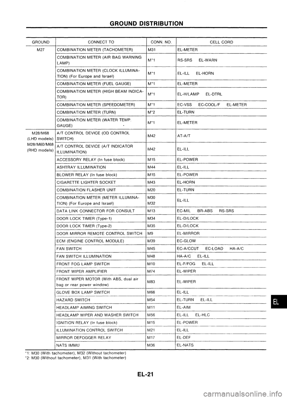
GROUNDDISTRIBUTION
GROUND CONNECT
TO CONN.NO.
CELLCORD
M27 COMBINATION
METER(TACHOMETER) M31EL-METER
COMBINATION METER(AIRBAG WARNING
M'1 RS-SRSEL-WARN
LAMP)
COMBINATION METER(CLOCK ILLUMINA-
M'1 EL-ILL
EL-HORN
TION) (ForEurope andIsrael)
COMBINATION METER(FUELGAUGE) M'1
EL-METER
COMBINATION METER(HIGHBEAM INDICA-
M'1 EL-H/LAMPEL-DTRL
TOR)
COMBINATION METER(SPEEDOMETER) M'1
EC-VSSEC-COOLIF EL-METER
COMBINATION METER(TURN) M'2EL-TURN
COMBINATION METER(WATER TEMP.
M'1 EL-METER
GAUGE)
.
M28/M68
A/T
CONTROL DEVICE(ODCONTROL
(LHD models)
SWITCH) M42
AT-A/T
M28/M60/M68
A/T
CONTROL DEVICE
(A/T
INDICATOR
(RHD models)
ILLUMINATION) M42
EL-ILL
ACCESSORY RELAY(Infuse block) M15
EL-POWER
ASHTRAY ILLUMINATION M44
EL-ILL
BLOWER RELAY(Infuse block) M15
EL-POWER
CIGARETTE LIGHTERSOCKET M43
EL-HORN
COMBINATION FLASHERUNIT M20EL-TURN
COMBINATION METER(METER ILLUMINA- M30
TION) (ForEurope andIsrael) M32EL-ILL
DATA LINKCONNECTOR FORCONSULT M13
EC-MILBR-ABS RS-SRS
DOOR LOCKTIMER (Type-1) M34
EL-D/LOCK
DOOR LOCKTIMER (Type-2) M35EL-D/LOCK
DOOR MIRROR REMOTE CONTROL SWITCHM9 EL-MIRROR
ECM (ENGINE CONTROL MODULE) M39EC-GLOW
FAN SWITCH M45
EC-A/CCUT
EC-LOADHA-A/C
FAN SWITCH ILLUMINATION M48HA-A/C
EL-ILL
FRONT FOGLAMP SWITCH M10EL-F/FOG
EL-ILL
FRONT WIPERAMPLIFIER M74
EL-WIPER
FRONT WIPERMOTOR (WithASS,dualair
M83 EL-WIPER
bag orrear power window)
GLOVE BOXLAMP SWITCH M66EL-ILL
HAZARD SWITCH M54
EL-TURN
EL-ILL
HEADLAMP AIMINGSWITCH M11EL-AIM
HEADLAMP WIPERANDWASHER SWITCH M56 EL-ILL
EL-HLC
IGNITION RELAY(Infuse block) M15EL-POWER
ILLUMINATION CONTROLSWITCH M21
EL-ILL
MIRROR DEFOGGER RELAY M17
EL-DEF
NATS IMMU M36EL-NATS
'1: M30 (With tachometer), M32(Without tachometer)
'2: M30 (Without tachometer), M31(With tachometer)
EL-21
•
Page 426 of 1701

CHARGINGSYSTEM
Trouble Diagnoses
Before conducting analternator test,make surethatthebattery isfully charged. A3D-volt voltmeter and
suitable testprobes arenecessary forthe test. Thealternator canbechecked easilybyreferring tothe
Inspection Table.
Before starting, inspectthefusible link.
WITH IeREGULATOR
Burned-out
bulb.
Replace and
proceed to
"@".
Light "ON"
Light "OFF"
Connect
connector (S,
L) and
ground F
terminal
Engine
speed: 1,500 rpm
(Measure B
terminal
voltage)
Make sure
connector (S,L)is
connected
correctly.
(HITACHI
make)
'See
4)for grounding Fterminal.
(MITSUBISHI
make)
Check or
replace drive
belt.
Light "ON"
Light "OFF"
Disconnect
connector (S,
L) and
ground L
lead wire.
Engine
speed:
1,500 rpm
Lighting
switch "ON"
With
alternator sideLterminal
grounded. internalshortoccurs
when
+
diode isshort-circuited.
Light "ON
Dim
light
Light flickers
Bright light
Light
"ON"
Light
"OFF"
Ignition
switch "ON"
@
1) Use fully charged battery.
2) light: Charge warning light
ACG :Alternator partsexcept I'Cregulator
IC-RG :IC regulator
OK :IC-alternator isingood condition.
3) When reaching "Damaged ACG",remove
alternator fromvehicle anddisassembly, inspect
and correct orreplace faultyparts.
4) *Method ofgrounding Fterminal (HITACHI make
only)
Gasoline enginemodel
Contact tipofwire withbrush andattach
wire toalternator body.
~~~
;;z..'~~.~
~~~/j
S$.~~'
s<(r~, -
Brush liftwire
;;.. ~ Q<:::z"d,l'T7.
~ .. ~ ~-)o,IJ!"-f/
- -~~ C);
0~~/
'~-/i ~-,~
-~j~n
- <::::; -~ \•
'" 1A/-'
SEL030Z
5) Terminals
"S","l","B"
and
"E"
aremarked onrear cover ofalternator.
EL-54
Page 443 of 1701

<fill)
(£106)
COMBINATION
METER
(CHA")
HEADlAMP-Daytime LightSystem -
Wiring Diagram -DTRl -
•
Refer
to
EL-POWER.
Gasoline engine
With tachometer
Without
tachometer
EL-DTRL-01
FUSE
BLOCK
(JIB)
(£106)
COMBINATION
METER
(CHARGEWARNING
LAMP)
~
~
Refertolast page
(Foldout page).
10A
IT]
~
Y
1
R~W:} Nextpage
----B/R~
Y
~
~
IR
rn~
I
~g~~~CTOR
-1
@
~ @:
IR
@:
II~IQID
@:
T-'
(EiQD
IR
.
~
.'----- YIR
-{9>
Next page
•
Y
IR
*1
@
30
@
40
m
*2
@
40
'@
3
,
ALT -L DAYTIME
LIGHT
UNIT
(El1B)
BR
m
IGN
B/Y
m ST
•
•
GS
GS
Y
B/Y
IfWlJCMID
11:1~
B/Y
Y
1
Y
R/W
m
LH
FUSE
R
m
RH
FUSE
I
BATTERY
I
rr::-J;::-'Jl
15A
~I~
W~I
~1401
B/R RR/W
I
!
•
B/R
m
TAIL
FUSE
L ~
~---------------------,
I I
: ~ (~ITB)~
(E119):
I~GY~GYI
I I
L ~
~~
~ BR
HEL016
El-71
Page 523 of 1701

More than10-20
NO
Engine
start
(0.10-0.20, 0.1-0.2, 1.4-2.8)
Less than10-20
YES
Engine
stop")
Ohmmeter- + WARNING
LAMPSANDBUZZER
Oil Pressure SwitchCheck
Oil pressure
Continuity
kPa (bar, kg/cm
2,
psi)
More than10-20
NO
Engine
start
(0.10-0.20, 0.1-0.2, 1.4-2.8)
Less than10-20
YES
Engine
stop
(0.10-0.20, 0.1-0.2, 1.4-2.8)
SEL748K
Test lamp 3.4WON
\ ,I
"
/
Ballery
Test lamp 3.4W OFF
~0
CD
Ballery
Gasoline MEL623D
SEL901F
Check
thecontinuity betweentheterminals ofoil pressure
switch andbody ground.
Fuel Warning LampSensor Check
• Itwill take ashort timeforthe bulb tolight.
Diode Check
• Check continuity usinganohmmeter.
• Diode isfunctioning properlyiftest results areasshown in
the figure atleft.
NOTE:
Specification mayvary depending onthe type oftester. Before
performing thisinspection, besure torefer tothe instruction
manual forthe tester tobe used.
• Diodes forwarning lampsarebuilt intothecombination
meter printed circuit.
Refer to"Combination Meter"(EL-127).
Warning BuzzerUnit
• Seat beltwarning lampiscontrolled bythe warning buzzer
unit.
Refer to"Warning Buzzer"(EL-152).
EL-151
•
Page 524 of 1701

• through 7.5Afuse (No.
[f")
WARNINGLAMPSANDBUZZER
Warning Buzzer/System Description
The warning buzzeriscontrolled bythe warning buzzerunit.
Power issupplied atall times
(RHD models exceptforEurope)
• through 7.5Afuse (No.
[fA],
located inthe fuse block)
• tokey switch terminal
CD.
Power issupplied atall times
(LHD models withoutdaytime lightsystem)
• through 75Afusible link(letter
[.9J,
located inthe fusible linkand fuse box).
• tolighting switchterminal
@.
(LHD models withdaytime lightsystem andRHD models)
• through 10Afuse (No.
~J,
located inthe fuse block)
• tolighting switchterminal
@.
Power issupplied atall times
(Except forAustralia)
• through 7.5Afuse (No.~,located inthe fusible linkand fuse box)
• torear foglamp switch terminal
CD.
With theignition switchinthe ONorSTART position, powerissupplied
• through 7.5Afuse (No.
11J,
located inthe fuse block)
• towarning buzzerunitterminal
@
(LHD models exceptforAustralia) or
CD
(For Australia).
When driver's doorisopened, groundissupplied
• through bodygrounds
@
and
@
• todriver's sidedoor switch terminal
@
• through driver'ssidedoor switch terminal
G)
• towarning buzzerunitterminal
@
(Except forAustralia) or
(J)
(For Australia).
With power andground supplied, thewarning buzzerwillsound.
Ignition keywarning buzzer(RHOmodels exceptforEurope)
With thekey inthe ignition switchinthe OFF position, andthedriver's dooropen, thewarning buzzer
will sound. Abattery positive voltageissupplied
• from keyswitch terminal
CID
• towarning buzzerunitterminal
CID
(Except forAustralia) or
@)
(For Australia).
Ground issupplied
• from driver sidedoor switch terminal
G)
• towarning buzzerunitterminal
@
(Except forAustralia) or
(J)
(For Australia).
Driver sidedoor switch terminal
@
isgrounded throughbodygrounds
@
and
@.
Light warning buzzer
With ignition switchOFF,driver's dooropen, andlighting switchin1ST or2ND position, warningbuzzer
will sound. Abattery positive voltageissupplied
(LHD models withoutdaytime lightsystem)
• from lighting switchterminal
@
• through 10Afuse (No.
@ID,
located inthe fusible linkand. fuse box)
• towarning buzzerunitterminal
@>.
(LHD models withdaytime lightsystem)
• from lighting switchterminal
@
• todaytime lightunitterminal
@
• through daytime lightunitterminal
@>
• towarning buzzerunitterminal
@>
(RHD models)
• from lighting switchterminal
@
• towarning buzzerunitterminal
@>
(Except forAustralia) or
@
(For Australia).
Ground issupplied
• from driver sidedoor switch terminal
G)
• towarning buzzerunitterminal
@
(Except forAustralia) or
(J)
(For Australia).
Driver sidedoor switch terminal
@
isgrounded throughbodygrounds
(!ill
and
@.
Rear foglamp switch warning buzzer(ForEurope models)
With ignition switchOFF,driver's dooropen, andrear foglamp switch ON,warning buzzerwillsound.
A battery positive voltageissupplied
EL-152
Page 526 of 1701
![NISSAN ALMERA N15 1995 Service Manual WARNINGLAMPSANDBUZZER
Warning Buzzer/Wiring Diagram-BUZZER -
LHD MODELS
EL-BUZZER-01
DOOR
SWITCH
DRIVER'S
SIDE
(]ID
OPEN
Refer
to
EL-POWER.
CLOSED
IJ:i=n
B
•
f.
B B
~ ~
@ll)@
FUSE
BL](/img/5/57349/w960_57349-525.png "NISSAN ALMERA N15 1995 Service Manual WARNINGLAMPSANDBUZZER
Warning Buzzer/Wiring Diagram-BUZZER -
LHD MODELS
EL-BUZZER-01
DOOR
SWITCH
DRIVER'S
SIDE
(]ID
OPEN
Refer
to
EL-POWER.
CLOSED
IJ:i=n
B
•
f.
B B
~ ~
@ll)@
FUSE
BL")
WARNINGLAMPSANDBUZZER
Warning Buzzer/Wiring Diagram-BUZZER -
LHD MODELS
EL-BUZZER-01
DOOR
SWITCH
DRIVER'S
SIDE
(]ID
OPEN
Refer
to
EL-POWER.
CLOSED
IJ:i=n
B
•
f.
B B
~ ~
@ll)@
FUSE
BLOCK
(JIB)
~
m
IN~41
@:
Withdaytime lightsystem
G1@:WithoutdaytimelightsYstem
*1".@B/R @W
,
G *2...
@
RIL @W/R
•
~ *3".@R/B @R/Y
1I1DI •
IGN WARNING
SW BUZZER
RR FOG DOORUNIT
SW SW(DR)
@
lbjdJ ~
PU/R R
[ttl ']'t4IJUNCTION
BOX NO.2
(JOINT
CONNECTORS)
~------1I~41
PU/R
t
~@)
m
REAR
[jJ
(]V
IND FOG R
LAMP ~
SWITCH II1II
~
OFF
7.5A
1431
B/R
rm
TAIL/L FUSE
I!JjJJ
*2
I
O~ DL W/R
[iJt~:1
R/Y
t
I_-.I~o
tt
RIB
Ii1'on
TAILIL
OUTPUT
RIL
will
TAILIL
SW
\bj::tl
B
rn~
I
JOINT
CONNECTOR-3
I
lU ....,
DAYTIME
=jF
I
LIGHT B
UNIT BB
I..-.--
---J~~
I
BATTERY
I
•
~-17-5A-~'
10.
m
1361
W B/R P
!
I.-",
1$1
~~1)
*1 P
will
L
LIGHTING
SWITCH
~
~~
~BR
IIITIillIIITIIT
@
~BR
~~@)
56j8191OU12 W
r1TmCW
TIT'
B
Refer
tolast page
(Foldout page).
(BID ~
•
~ (106)
•
~~
~GY
HEL083
EL-154