relay NISSAN ALMERA N16 2001 Electronic Service Manual
[x] Cancel search | Manufacturer: NISSAN, Model Year: 2001, Model line: ALMERA N16, Model: NISSAN ALMERA N16 2001Pages: 2493, PDF Size: 66.97 MB
Page 764 of 2493
3 DETECT MALFUNCTIONING PART
Check the following.
+10A fuse
+15A fuse
+Harness for open or short between fuse and fuel pump relay
©Repair harness or connectors.
4 CHECK POWER GROUND CIRCUIT
1. Turn ignition switch ªOFFº.
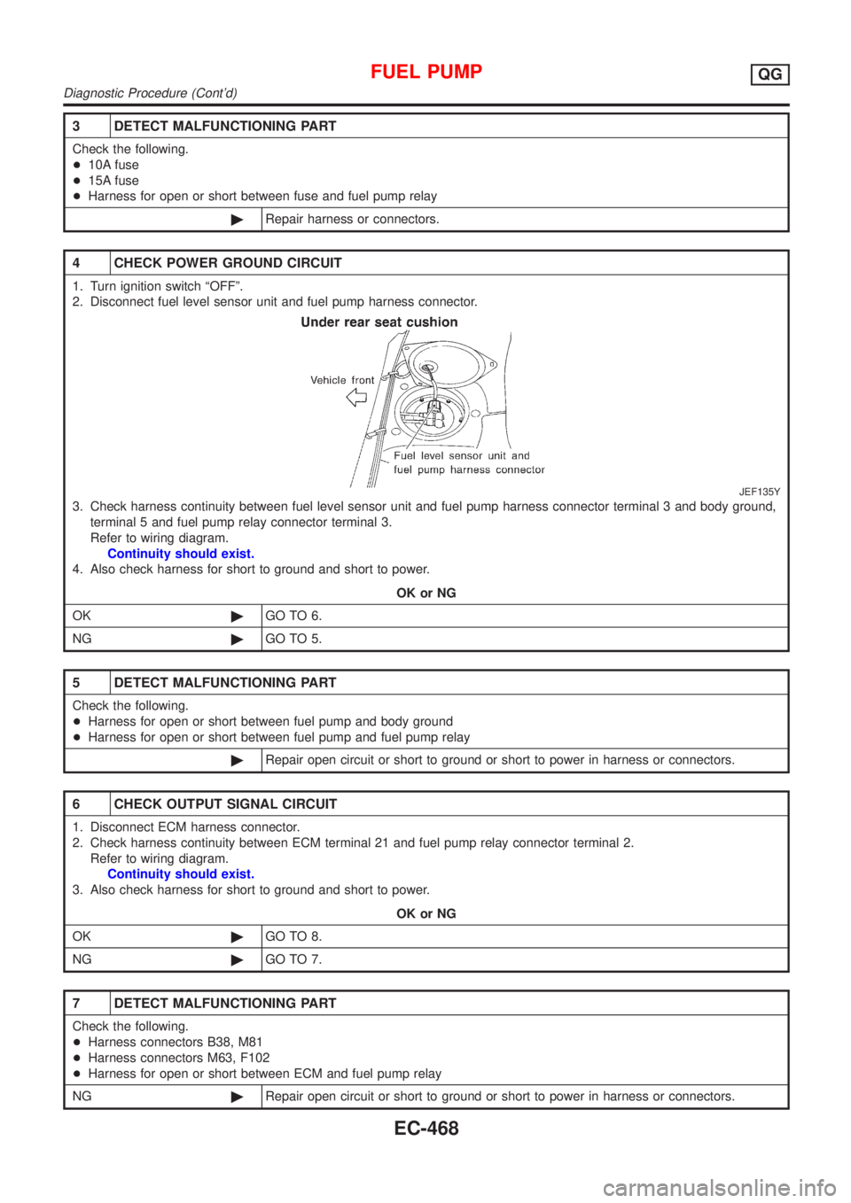
2. Disconnect fuel level sensor unit and fuel pump harness connector.
JEF135Y
3. Check harness continuity between fuel level sensor unit and fuel pump harness connector terminal 3 and body ground,
terminal 5 and fuel pump relay connector terminal 3.
Refer to wiring diagram.
Continuity should exist.
4. Also check harness for short to ground and short to power.
OK or NG
OK©GO TO 6.
NG©GO TO 5.
5 DETECT MALFUNCTIONING PART
Check the following.
+Harness for open or short between fuel pump and body ground
+Harness for open or short between fuel pump and fuel pump relay
©Repair open circuit or short to ground or short to power in harness or connectors.
6 CHECK OUTPUT SIGNAL CIRCUIT
1. Disconnect ECM harness connector.
2. Check harness continuity between ECM terminal 21 and fuel pump relay connector terminal 2.
Refer to wiring diagram.
Continuity should exist.
3. Also check harness for short to ground and short to power.
OK or NG
OK©GO TO 8.
NG©GO TO 7.
7 DETECT MALFUNCTIONING PART
Check the following.
+Harness connectors B38, M81
+Harness connectors M63, F102
+Harness for open or short between ECM and fuel pump relay
NG©Repair open circuit or short to ground or short to power in harness or connectors.
FUEL PUMPQG
Diagnostic Procedure (Cont'd)
EC-468
Page 765 of 2493
8 CHECK FUEL PUMP RELAY
Refer to ªComponent Inspectionº, EC-469.
OK or NG
OK©GO TO 9.
NG©Replace fuel pump relay.
9 CHECK FUEL PUMP
Refer to ªComponent Inspectionº, EC-469.
OK or NG
OK©GO TO 10.
NG©Replace fuel pump.
10 CHECK INTERMITTENT INCIDENT
Perform ªTROUBLE DIAGNOSIS FOR INTERMITTENT INCIDENTº, EC-144.
©INSPECTION END
SEF145X
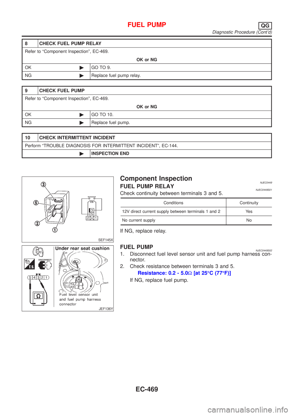
Component InspectionNJEC0449FUEL PUMP RELAYNJEC0449S01Check continuity between terminals 3 and 5.
Conditions Continuity
12V direct current supply between terminals 1 and 2 Yes
No current supply No
If NG, replace relay.
JEF136Y
FUEL PUMPNJEC0449S021. Disconnect fuel level sensor unit and fuel pump harness con-
nector.
2. Check resistance between terminals 3 and 5.
Resistance: 0.2 - 5.0W[at 25ÉC (77ÉF)]
If NG, replace fuel pump.
FUEL PUMPQG
Diagnostic Procedure (Cont'd)
EC-469
Page 782 of 2493
11 CHECK HEADLAMP INPUT SIGNAL CIRCUIT
Without Daytime Light system
1. Stop engine.
2. Disconnect ECM harness connector.
3. Disconnect lighting switch connector.
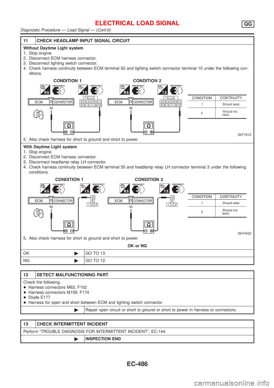
4. Check harness continuity between ECM terminal 50 and lighting switch connector terminal 10 under the following con-
ditions.
SEF161Z
5. Also check harness for short to ground and short to power.
With Daytime Light system
1. Stop engine.
2. Disconnect ECM harness connector.
3. Disconnect headlamp relay LH connector.
4. Check harness continuity between ECM terminal 50 and headlamp relay LH connector terminal 3 under the following
conditions.
SEF445Z
5. Also check harness for short to ground and short to power.
OK or NG
OK©GO TO 13.
NG©GO TO 12.
12 DETECT MALFUNCTIONING PART
Check the following.
+Harness connectors M63, F102
+Harness connectors M159, F174
+Diode E177
+Harness for open and short between ECM and lighting switch connector
©Repair open circuit or short to ground or short to power in harness or connectors.
13 CHECK INTERMITTENT INCIDENT
Perform ªTROUBLE DIAGNOSIS FOR INTERMITTENT INCIDENTº, EC-144.
©INSPECTION END
ELECTRICAL LOAD SIGNALQG
Diagnostic Procedure Ð Load Signal Ð (Cont'd)
EC-486
Page 800 of 2493
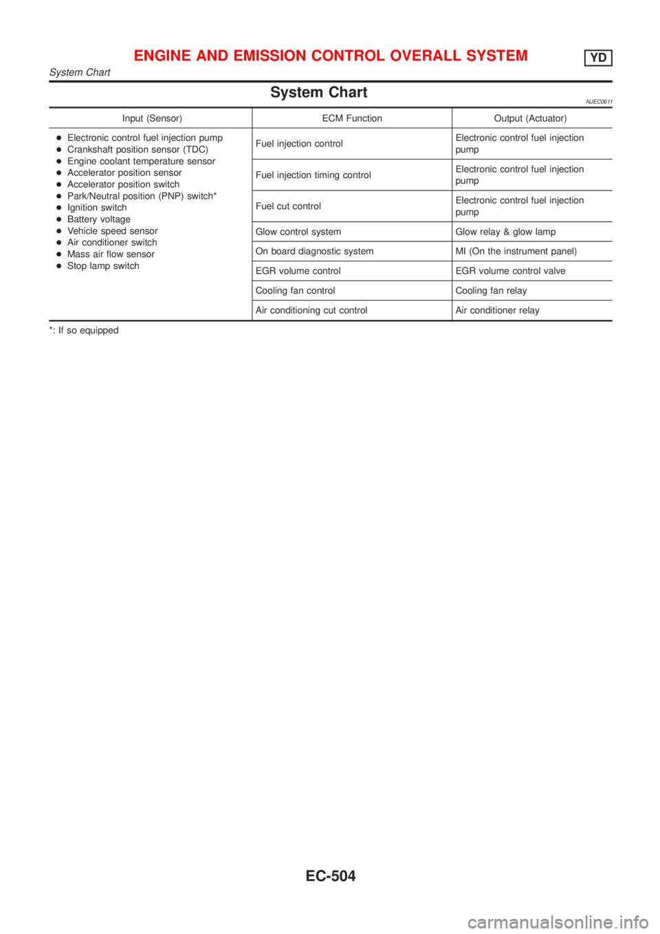
System ChartNJEC0611
Input (Sensor) ECM Function Output (Actuator)
+Electronic control fuel injection pump
+Crankshaft position sensor (TDC)
+Engine coolant temperature sensor
+Accelerator position sensor
+Accelerator position switch
+Park/Neutral position (PNP) switch*
+Ignition switch
+Battery voltage
+Vehicle speed sensor
+Air conditioner switch
+Mass air flow sensor
+Stop lamp switchFuel injection controlElectronic control fuel injection
pump
Fuel injection timing controlElectronic control fuel injection
pump
Fuel cut controlElectronic control fuel injection
pump
Glow control system Glow relay & glow lamp
On board diagnostic system MI (On the instrument panel)
EGR volume control EGR volume control valve
Cooling fan control Cooling fan relay
Air conditioning cut control Air conditioner relay
*: If so equipped
ENGINE AND EMISSION CONTROL OVERALL SYSTEMYD
System Chart
EC-504
Page 803 of 2493
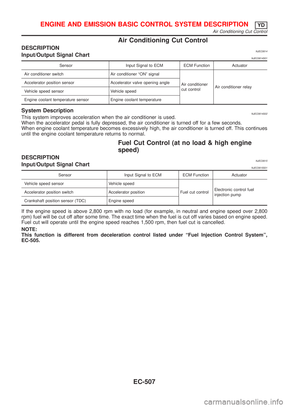
Air Conditioning Cut Control
DESCRIPTIONNJEC0614Input/Output Signal ChartNJEC0614S01
Sensor Input Signal to ECM ECM Function Actuator
Air conditioner switch Air conditioner ªONº signal
Air conditioner
cut controlAir conditioner relay Accelerator position sensor Accelerator valve opening angle
Vehicle speed sensor Vehicle speed
Engine coolant temperature sensor Engine coolant temperature
System DescriptionNJEC0614S02This system improves acceleration when the air conditioner is used.
When the accelerator pedal is fully depressed, the air conditioner is turned off for a few seconds.
When engine coolant temperature becomes excessively high, the air conditioner is turned off. This continues
until the engine coolant temperature returns to normal.
Fuel Cut Control (at no load & high engine
speed)
DESCRIPTIONNJEC0615Input/Output Signal ChartNJEC0615S01
Sensor Input Signal to ECM ECM Function Actuator
Vehicle speed sensor Vehicle speed
Fuel cut controlElectronic control fuel
injection pump Accelerator position switch Accelerator position
Crankshaft position sensor (TDC) Engine speed
If the engine speed is above 2,800 rpm with no load (for example, in neutral and engine speed over 2,800
rpm) fuel will be cut off after some time. The exact time when the fuel is cut off varies based on engine speed.
Fuel cut will operate until the engine speed reaches 1,500 rpm, then fuel cut is cancelled.
NOTE:
This function is different from deceleration control listed under ªFuel Injection Control Systemº,
EC-505.
ENGINE AND EMISSION BASIC CONTROL SYSTEM DESCRIPTIONYD
Air Conditioning Cut Control
EC-507
Page 824 of 2493
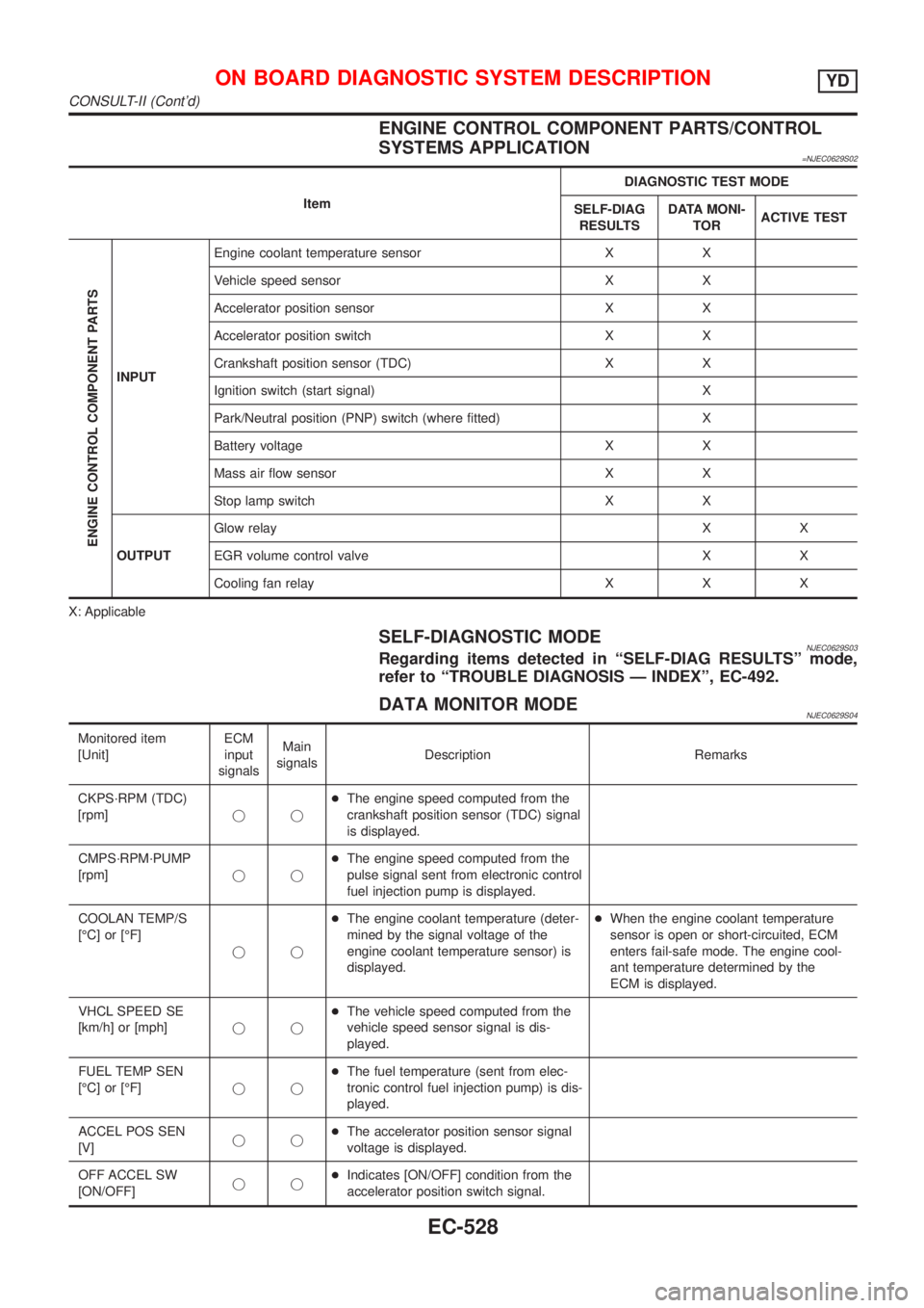
ENGINE CONTROL COMPONENT PARTS/CONTROL
SYSTEMS APPLICATION
=NJEC0629S02
ItemDIAGNOSTIC TEST MODE
SELF-DIAG
RESULTSDATA MONI-
TORACTIVE TEST
ENGINE CONTROL COMPONENT PARTS
INPUTEngine coolant temperature sensor X X
Vehicle speed sensor X X
Accelerator position sensor X X
Accelerator position switch X X
Crankshaft position sensor (TDC) X X
Ignition switch (start signal) X
Park/Neutral position (PNP) switch (where fitted) X
Battery voltage X X
Mass air flow sensor X X
Stop lamp switch X X
OUTPUTGlow relayXX
EGR volume control valve X X
Cooling fan relay X X X
X: Applicable
SELF-DIAGNOSTIC MODENJEC0629S03Regarding items detected in ªSELF-DIAG RESULTSº mode,
refer to ªTROUBLE DIAGNOSIS Ð INDEXº, EC-492.
DATA MONITOR MODENJEC0629S04
Monitored item
[Unit]ECM
input
signalsMain
signalsDescription Remarks
CKPS´RPM (TDC)
[rpm]jj+The engine speed computed from the
crankshaft position sensor (TDC) signal
is displayed.
CMPS´RPM´PUMP
[rpm]jj+The engine speed computed from the
pulse signal sent from electronic control
fuel injection pump is displayed.
COOLAN TEMP/S
[ÉC] or [ÉF]
jj+The engine coolant temperature (deter-
mined by the signal voltage of the
engine coolant temperature sensor) is
displayed.+When the engine coolant temperature
sensor is open or short-circuited, ECM
enters fail-safe mode. The engine cool-
ant temperature determined by the
ECM is displayed.
VHCL SPEED SE
[km/h] or [mph]jj+The vehicle speed computed from the
vehicle speed sensor signal is dis-
played.
FUEL TEMP SEN
[ÉC] or [ÉF]jj+The fuel temperature (sent from elec-
tronic control fuel injection pump) is dis-
played.
ACCEL POS SEN
[V]jj+The accelerator position sensor signal
voltage is displayed.
OFF ACCEL SW
[ON/OFF]jj+Indicates [ON/OFF] condition from the
accelerator position switch signal.
ON BOARD DIAGNOSTIC SYSTEM DESCRIPTIONYD
CONSULT-II (Cont'd)
EC-528
Page 825 of 2493
![NISSAN ALMERA N16 2001 Electronic Service Manual Monitored item
[Unit]ECM
input
signalsMain
signalsDescription Remarks
SPILL/V [ÉCA]
j+The control position of spill valve (sent
from electronic control fuel injection
pump) is displayed.
BATTERY VOLT](/img/5/57351/w960_57351-824.png "NISSAN ALMERA N16 2001 Electronic Service Manual Monitored item
[Unit]ECM
input
signalsMain
signalsDescription Remarks
SPILL/V [ÉCA]
j+The control position of spill valve (sent
from electronic control fuel injection
pump) is displayed.
BATTERY VOLT")
Monitored item
[Unit]ECM
input
signalsMain
signalsDescription Remarks
SPILL/V [ÉCA]
j+The control position of spill valve (sent
from electronic control fuel injection
pump) is displayed.
BATTERY VOLT [V]
jj+The power supply voltage of ECM is
displayed.
P/N POSI SW*1
[ON/OFF] (where
fitted)jj+Indicates [ON/OFF] condition from the
park/neutral position switch signal.
START SIGNAL
[ON/OFF]jj+Indicates [ON/OFF] condition from the
starter signal.+After starting the engine, [OFF] is dis-
played regardless of the starter signal.
BRAKE SW
[ON/OFF]jj+Indicates [ON/OFF] condition from the
stop lamp switch signal.
BRAKE SW2
[ON/OFF]jj+Indicates [ON/OFF] condition from the
brake pedal position switch signal.
IGN SW
[ON/OFF]jj+Indicates [ON/OFF] condition from igni-
tion switch signal.
MAS AIR/FL SE [V]
jj+The signal voltage of the mass air flow
sensor is displayed.+When the engine is stopped, a certain
value is indicated.
INT/A VOLUME [mg/]+The intake air volume computed from
the mass air flow sensor signal is dis-
played.
F/CUT SIGNAL
[ON/OFF]
j+The [ON/OFF] condition from decelera-
tion fuel cut signal (sent from electronic
control fuel injection pump) is displayed.
OFF´´´Fuel is cut off.
ON´´´Fuel is not cut off.
GLOW RLY
[ON/OFF]j+The glow relay control condition (deter-
mined by ECM according to the input
signal) is displayed.
COOLING FAN
[LOW/HI/OFF]
j+Indicates the control condition of the
cooling fans (determined by ECM
according to the input signal).
+LOW ... Operates at low speed.
HI ... Operates at high speed.
OFF ... Stopped.
BARO SEN [kPa]
jj+The barometric pressure (determined
by the signal voltage from the baromet-
ric pressure sensor built into the ECM)
is displayed.
EGR VOL CON/V
[step]
j+Indicates the EGR volume control value
computed by the ECM according to the
input signals.
+The opening becomes larger as the
value increases.
*1: On models not equipped with park/neutral position (PNP) switch, ªOFFº is always displayed regardless of gear shift position.
NOTE:
Any monitored item that does not match the vehicle being diagnosed is deleted from the display automatically.
ON BOARD DIAGNOSTIC SYSTEM DESCRIPTIONYD
CONSULT-II (Cont'd)
EC-529
Page 826 of 2493
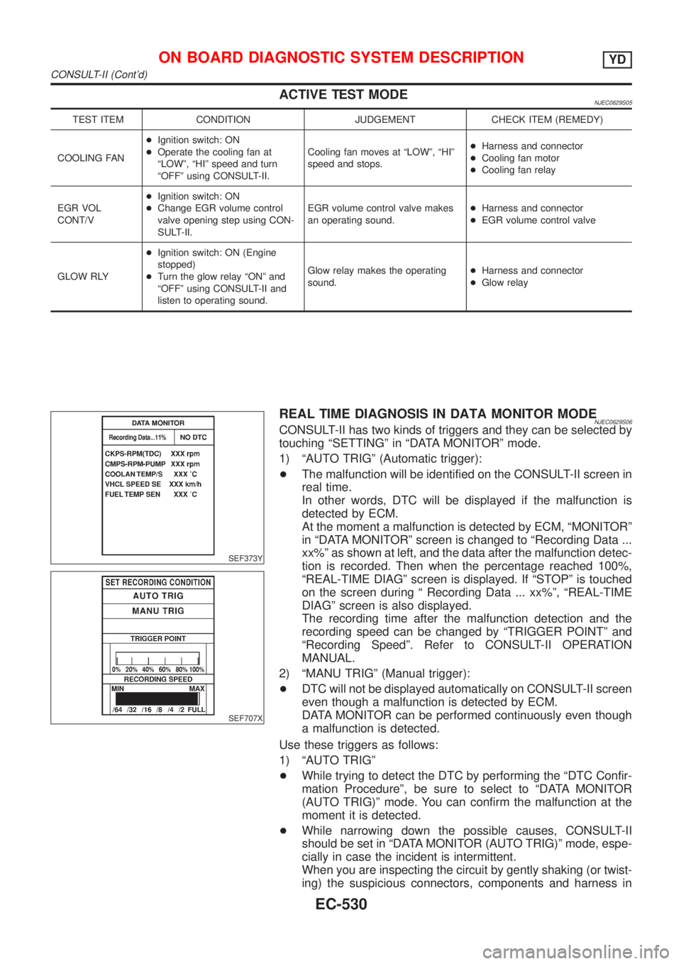
ACTIVE TEST MODENJEC0629S05
TEST ITEM CONDITION JUDGEMENT CHECK ITEM (REMEDY)
COOLING FAN+Ignition switch: ON
+Operate the cooling fan at
ªLOWº, ªHIº speed and turn
ªOFFº using CONSULT-II.Cooling fan moves at ªLOWº, ªHIº
speed and stops.+Harness and connector
+Cooling fan motor
+Cooling fan relay
EGR VOL
CONT/V+Ignition switch: ON
+Change EGR volume control
valve opening step using CON-
SULT-II.EGR volume control valve makes
an operating sound.+Harness and connector
+EGR volume control valve
GLOW RLY+Ignition switch: ON (Engine
stopped)
+Turn the glow relay ªONº and
ªOFFº using CONSULT-II and
listen to operating sound.Glow relay makes the operating
sound.+Harness and connector
+Glow relay
SEF373Y
SEF707X
REAL TIME DIAGNOSIS IN DATA MONITOR MODENJEC0629S06CONSULT-II has two kinds of triggers and they can be selected by
touching ªSETTINGº in ªDATA MONITORº mode.
1) ªAUTO TRIGº (Automatic trigger):
+The malfunction will be identified on the CONSULT-II screen in
real time.
In other words, DTC will be displayed if the malfunction is
detected by ECM.
At the moment a malfunction is detected by ECM, ªMONITORº
in ªDATA MONITORº screen is changed to ªRecording Data ...
xx%º as shown at left, and the data after the malfunction detec-
tion is recorded. Then when the percentage reached 100%,
ªREAL-TIME DIAGº screen is displayed. If ªSTOPº is touched
on the screen during ª Recording Data ... xx%º, ªREAL-TIME
DIAGº screen is also displayed.
The recording time after the malfunction detection and the
recording speed can be changed by ªTRIGGER POINTº and
ªRecording Speedº. Refer to CONSULT-II OPERATION
MANUAL.
2) ªMANU TRIGº (Manual trigger):
+DTC will not be displayed automatically on CONSULT-II screen
even though a malfunction is detected by ECM.
DATA MONITOR can be performed continuously even though
a malfunction is detected.
Use these triggers as follows:
1) ªAUTO TRIGº
+While trying to detect the DTC by performing the ªDTC Confir-
mation Procedureº, be sure to select to ªDATA MONITOR
(AUTO TRIG)º mode. You can confirm the malfunction at the
moment it is detected.
+While narrowing down the possible causes, CONSULT-II
should be set in ªDATA MONITOR (AUTO TRIG)º mode, espe-
cially in case the incident is intermittent.
When you are inspecting the circuit by gently shaking (or twist-
ing) the suspicious connectors, components and harness in
ON BOARD DIAGNOSTIC SYSTEM DESCRIPTIONYD
CONSULT-II (Cont'd)
EC-530
Page 845 of 2493
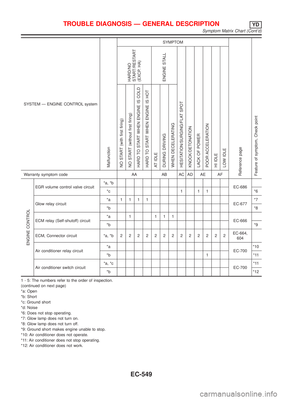
SYSTEM Ð ENGINE CONTROL system
Malfunction
SYMPTOM
Reference page
Feature of symptom, Check pointHARD/NO
START/RESTART
(EXCP. HA)
ENGINE STALL
HESITATION/SURGING/FLAT SPOT
KNOCK/DETONATION
LACK OF POWER
POOR ACCELERATION
HI IDLE
LOW IDLE NO START (with first firing)
NO START (without first firing)
HARD TO START WHEN ENGINE IS COLD
HARD TO START WHEN ENGINE IS HOT
AT IDLE
DURING DRIVING
WHEN DECELERATINGWarranty symptom code AA AB AC AD AE AF
ENGINE CONTROL
EGR volume control valve circuit*a, *b
EC-686
*c 1 1 1 *6
Glow relay circuit*a 1111
EC-677*7
*b*8
ECM relay (Self-shutoff) circuit*a 1 111
EC-666
*b*9
ECM, Connector circuit *a, *b2222222222222EC-664,
604
Air conditioner relay circuit*a
EC-700*10
*b 1 *11
Air conditioner switch circuit*a, *c
EC-700*11
*b*12
1 - 5: The numbers refer to the order of inspection.
(continued on next page)
*a: Open
*b: Short
*c: Ground short
*d: Noise
*6: Does not stop operating.
*7: Glow lamp does not turn on.
*8: Glow lamp does not turn off.
*9: Ground short makes engine unable to stop.
*10: Air conditioner does not operate.
*11: Air conditioner does not stop operating.
*12: Air conditioner does not work.
TROUBLE DIAGNOSIS Ð GENERAL DESCRIPTIONYD
Symptom Matrix Chart (Cont'd)
EC-549
Page 846 of 2493
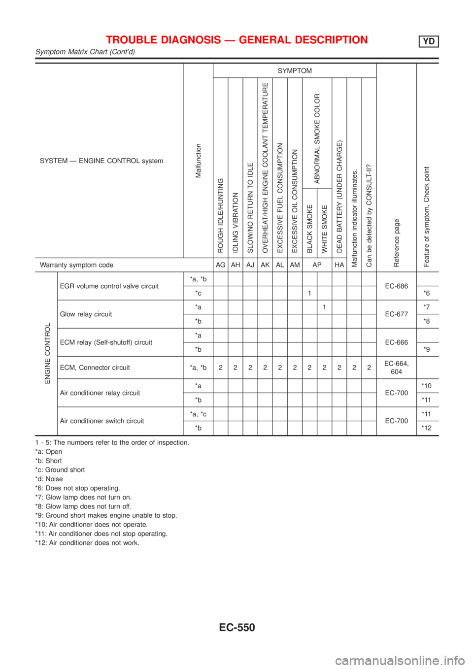
SYSTEM Ð ENGINE CONTROL system
Malfunction
SYMPTOM
Reference page
Feature of symptom, Check pointROUGH IDLE/HUNTING
IDLING VIBRATION
SLOW/NO RETURN TO IDLE
OVERHEAT/HIGH ENGINE COOLANT TEMPERATURE
EXCESSIVE FUEL CONSUMPTION
EXCESSIVE OIL CONSUMPTION
ABNORMAL SMOKE COLOR
DEAD BATTERY (UNDER CHARGE)
Malfunction indicator illuminates.
Can be detected by CONSULT-II?BLACK SMOKE
WHITE SMOKEWarranty symptom code AG AH AJ AK AL AM AP HA
ENGINE CONTROL
EGR volume control valve circuit*a, *b
EC-686
*c 1 *6
Glow relay circuit*a 1
EC-677*7
*b*8
ECM relay (Self-shutoff) circuit*a
EC-666
*b*9
ECM, Connector circuit *a, *b22222222222EC-664,
604
Air conditioner relay circuit*a
EC-700*10
*b*11
Air conditioner switch circuit*a, *c
EC-700*11
*b*12
1 - 5: The numbers refer to the order of inspection.
*a: Open
*b: Short
*c: Ground short
*d: Noise
*6: Does not stop operating.
*7: Glow lamp does not turn on.
*8: Glow lamp does not turn off.
*9: Ground short makes engine unable to stop.
*10: Air conditioner does not operate.
*11: Air conditioner does not stop operating.
*12: Air conditioner does not work.
TROUBLE DIAGNOSIS Ð GENERAL DESCRIPTIONYD
Symptom Matrix Chart (Cont'd)
EC-550