stop start NISSAN ALMERA N16 2001 Electronic Manual PDF
[x] Cancel search | Manufacturer: NISSAN, Model Year: 2001, Model line: ALMERA N16, Model: NISSAN ALMERA N16 2001Pages: 2493, PDF Size: 66.97 MB
Page 844 of 2493
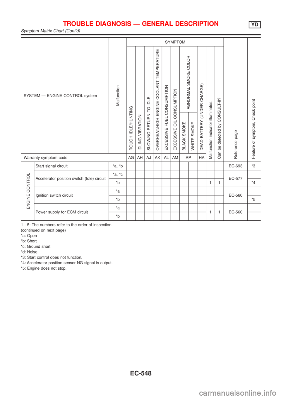
SYSTEM Ð ENGINE CONTROL system
Malfunction
SYMPTOM
Reference page
Feature of symptom, Check pointROUGH IDLE/HUNTING
IDLING VIBRATION
SLOW/NO RETURN TO IDLE
OVERHEAT/HIGH ENGINE COOLANT TEMPERATURE
EXCESSIVE FUEL CONSUMPTION
EXCESSIVE OIL CONSUMPTION
ABNORMAL SMOKE COLOR
DEAD BATTERY (UNDER CHARGE)
Malfunction indicator illuminates.
Can be detected by CONSULT-II?BLACK SMOKE
WHITE SMOKEWarranty symptom code AG AH AJ AK AL AM AP HA
ENGINE CONTROL
Start signal circuit *a, *b EC-693 *3
Accelerator position switch (Idle) circuit*a, *c
EC-577
*b 1 1 *4
Ignition switch circuit*a
EC-560
*b*5
Power supply for ECM circuit*a
1 1 EC-560
*b
1 - 5: The numbers refer to the order of inspection.
(continued on next page)
*a: Open
*b: Short
*c: Ground short
*d: Noise
*3: Start control does not function.
*4: Accelerator position sensor NG signal is output.
*5: Engine does not stop.
TROUBLE DIAGNOSIS Ð GENERAL DESCRIPTIONYD
Symptom Matrix Chart (Cont'd)
EC-548
Page 845 of 2493
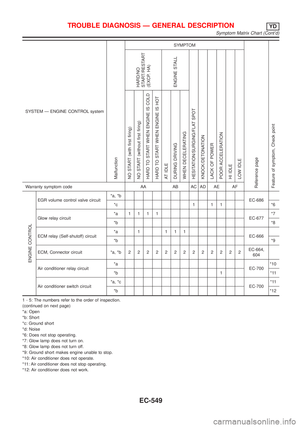
SYSTEM Ð ENGINE CONTROL system
Malfunction
SYMPTOM
Reference page
Feature of symptom, Check pointHARD/NO
START/RESTART
(EXCP. HA)
ENGINE STALL
HESITATION/SURGING/FLAT SPOT
KNOCK/DETONATION
LACK OF POWER
POOR ACCELERATION
HI IDLE
LOW IDLE NO START (with first firing)
NO START (without first firing)
HARD TO START WHEN ENGINE IS COLD
HARD TO START WHEN ENGINE IS HOT
AT IDLE
DURING DRIVING
WHEN DECELERATINGWarranty symptom code AA AB AC AD AE AF
ENGINE CONTROL
EGR volume control valve circuit*a, *b
EC-686
*c 1 1 1 *6
Glow relay circuit*a 1111
EC-677*7
*b*8
ECM relay (Self-shutoff) circuit*a 1 111
EC-666
*b*9
ECM, Connector circuit *a, *b2222222222222EC-664,
604
Air conditioner relay circuit*a
EC-700*10
*b 1 *11
Air conditioner switch circuit*a, *c
EC-700*11
*b*12
1 - 5: The numbers refer to the order of inspection.
(continued on next page)
*a: Open
*b: Short
*c: Ground short
*d: Noise
*6: Does not stop operating.
*7: Glow lamp does not turn on.
*8: Glow lamp does not turn off.
*9: Ground short makes engine unable to stop.
*10: Air conditioner does not operate.
*11: Air conditioner does not stop operating.
*12: Air conditioner does not work.
TROUBLE DIAGNOSIS Ð GENERAL DESCRIPTIONYD
Symptom Matrix Chart (Cont'd)
EC-549
Page 847 of 2493
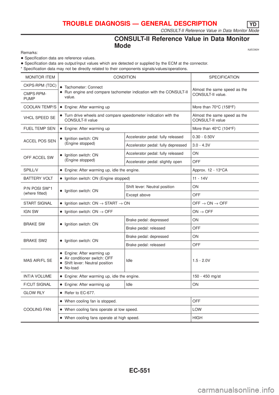
CONSULT-II Reference Value in Data Monitor
Mode
NJEC0634Remarks:
+Specification data are reference values.
+Specification data are output/input values which are detected or supplied by the ECM at the connector.
* Specification data may not be directly related to their components signals/values/operations.
MONITOR ITEM CONDITION SPECIFICATION
CKPS´RPM (TDC)
+Tachometer: Connect
+Run engine and compare tachometer indication with the CONSULT-II
value.Almost the same speed as the
CONSULT-II value. CMPS´RPM-
PUMP
COOLAN TEMP/S+Engine: After warming up More than 70ÉC (158ÉF)
VHCL SPEED SE+Turn drive wheels and compare speedometer indication with the
CONSULT-II valueAlmost the same speed as the
CONSULT-II value
FUEL TEMP SEN+Engine: After warming up More than 40ÉC (104ÉF)
ACCEL POS SEN+Ignition switch: ON
(Engine stopped)Accelerator pedal: fully released 0.30 - 0.50V
Accelerator pedal: fully depressed 3.0 - 4.3V
OFF ACCEL SW+Ignition switch: ON
(Engine stopped)Accelerator pedal: fully released ON
Accelerator pedal: slightly open OFF
SPILL/V+Engine: After warming up, idle the engine. Approx. 12 - 13ÉCA
BATTERY VOLT+Ignition switch: ON (Engine stopped) 11 - 14V
P/N POSI SW*1
(where fitted)+Ignition switch: ONShift lever: Neutral position ON
Except above OFF
START SIGNAL+Ignition switch: ON®START®ON OFF®ON®OFF
IGN SW+Ignition switch: ON®OFF ON®OFF
BRAKE SW+Ignition switch: ONBrake pedal: depressed ON
Brake pedal: released OFF
BRAKE SW2+Ignition switch: ONBrake pedal: depressed ON
Brake pedal: released OFF
MAS AIR/FL SE+Engine: After warming up
+Air conditioner switch: OFF
+Shift lever: Neutral position
+No-loadIdle 1.5 - 2.0V
INT/A VOLUME+Engine: After warming up, idle the engine. 150 - 450 mg/st
F/CUT SIGNAL+Engine: After warming up Idle ON
GLOW RLY+Refer to EC-677.
COOLING FAN+When cooling fan is stopped. OFF
+When cooling fans operate at low speed. LOW
+When cooling fans operate at high speed. HIGH
TROUBLE DIAGNOSIS Ð GENERAL DESCRIPTIONYD
CONSULT-II Reference Value in Data Monitor Mode
EC-551
Page 982 of 2493
DescriptionNJEC0764SYSTEM DESCRIPTIONNJEC0764S01
Sensor Input Signal to ECM ECM Function Actuator
Electronic controlled fuel injection pump Fuel injection signal
EGR volume con-
trolEGR volume control
valve Crankshaft position sensor (TDC) Engine speed
Vehicle speed sensor Vehicle speed
Engine coolant temperature sensor Engine coolant temperature
Ignition switch Start signal
Accelerator position sensor Accelerator position
Mass air flow sensor Amount of intake air
Air conditioner switch Air conditioner operation
Electrical load Electrical load signal
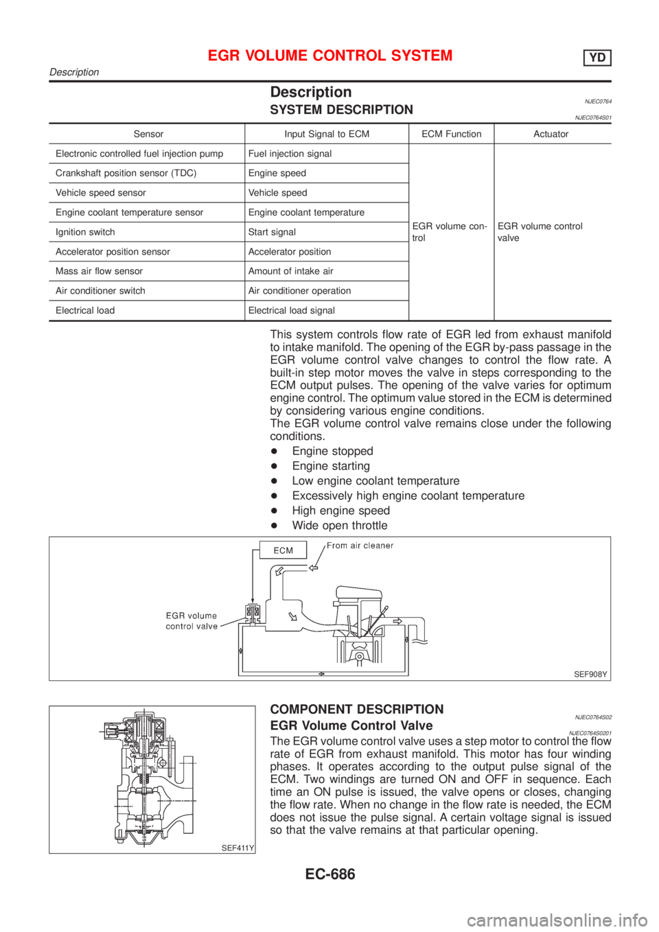
This system controls flow rate of EGR led from exhaust manifold
to intake manifold. The opening of the EGR by-pass passage in the
EGR volume control valve changes to control the flow rate. A
built-in step motor moves the valve in steps corresponding to the
ECM output pulses. The opening of the valve varies for optimum
engine control. The optimum value stored in the ECM is determined
by considering various engine conditions.
The EGR volume control valve remains close under the following
conditions.
+Engine stopped
+Engine starting
+Low engine coolant temperature
+Excessively high engine coolant temperature
+High engine speed
+Wide open throttle
SEF908Y
SEF411Y
COMPONENT DESCRIPTIONNJEC0764S02EGR Volume Control ValveNJEC0764S0201The EGR volume control valve uses a step motor to control the flow
rate of EGR from exhaust manifold. This motor has four winding
phases. It operates according to the output pulse signal of the
ECM. Two windings are turned ON and OFF in sequence. Each
time an ON pulse is issued, the valve opens or closes, changing
the flow rate. When no change in the flow rate is needed, the ECM
does not issue the pulse signal. A certain voltage signal is issued
so that the valve remains at that particular opening.
EGR VOLUME CONTROL SYSTEMYD
Description
EC-686
Page 1015 of 2493
JEM238G
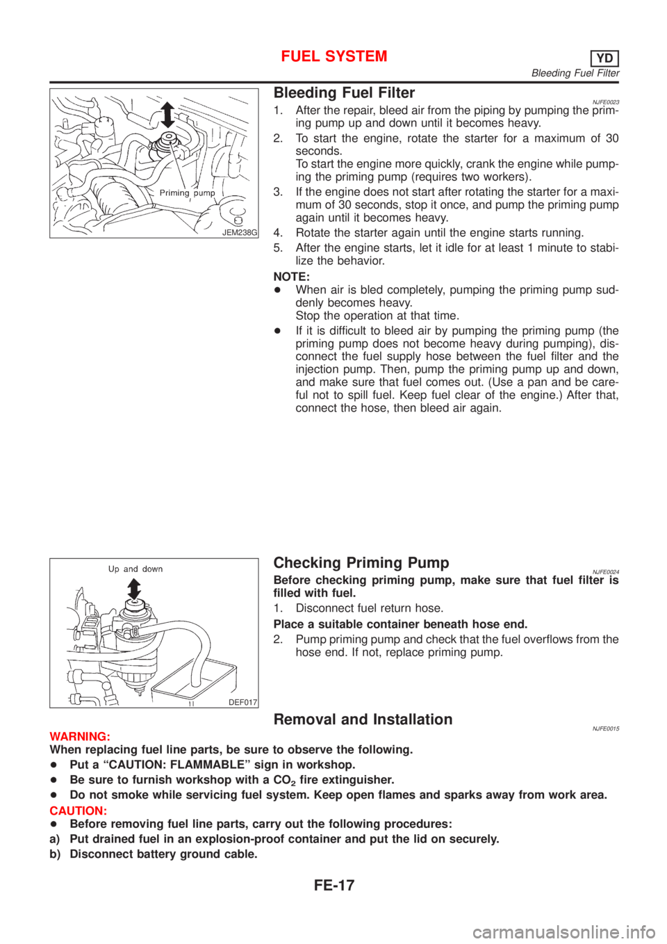
Bleeding Fuel FilterNJFE00231. After the repair, bleed air from the piping by pumping the prim-
ing pump up and down until it becomes heavy.
2. To start the engine, rotate the starter for a maximum of 30
seconds.
To start the engine more quickly, crank the engine while pump-
ing the priming pump (requires two workers).
3. If the engine does not start after rotating the starter for a maxi-
mum of 30 seconds, stop it once, and pump the priming pump
again until it becomes heavy.
4. Rotate the starter again until the engine starts running.
5. After the engine starts, let it idle for at least 1 minute to stabi-
lize the behavior.
NOTE:
+When air is bled completely, pumping the priming pump sud-
denly becomes heavy.
Stop the operation at that time.
+If it is difficult to bleed air by pumping the priming pump (the
priming pump does not become heavy during pumping), dis-
connect the fuel supply hose between the fuel filter and the
injection pump. Then, pump the priming pump up and down,
and make sure that fuel comes out. (Use a pan and be care-
ful not to spill fuel. Keep fuel clear of the engine.) After that,
connect the hose, then bleed air again.
DEF017
Checking Priming PumpNJFE0024Before checking priming pump, make sure that fuel filter is
filled with fuel.
1. Disconnect fuel return hose.
Place a suitable container beneath hose end.
2. Pump priming pump and check that the fuel overflows from the
hose end. If not, replace priming pump.
Removal and InstallationNJFE0015WARNING:
When replacing fuel line parts, be sure to observe the following.
+Put a ªCAUTION: FLAMMABLEº sign in workshop.
+Be sure to furnish workshop with a CO
2fire extinguisher.
+Do not smoke while servicing fuel system. Keep open flames and sparks away from work area.
CAUTION:
+Before removing fuel line parts, carry out the following procedures:
a) Put drained fuel in an explosion-proof container and put the lid on securely.
b) Disconnect battery ground cable.
FUEL SYSTEMYD
Bleeding Fuel Filter
FE-17
Page 1201 of 2493
SMA827CA
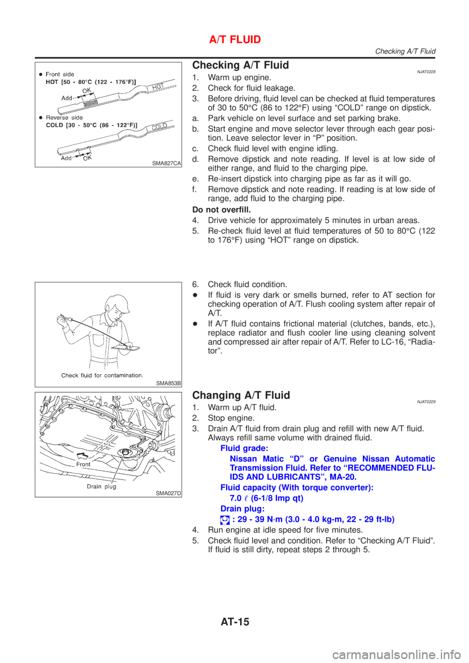
Checking A/T FluidNJAT02281. Warm up engine.
2. Check for fluid leakage.
3. Before driving, fluid level can be checked at fluid temperatures
of 30 to 50ÉC (86 to 122ÉF) using ªCOLDº range on dipstick.
a. Park vehicle on level surface and set parking brake.
b. Start engine and move selector lever through each gear posi-
tion. Leave selector lever in ªPº position.
c. Check fluid level with engine idling.
d. Remove dipstick and note reading. If level is at low side of
either range, and fluid to the charging pipe.
e. Re-insert dipstick into charging pipe as far as it will go.
f. Remove dipstick and note reading. If reading is at low side of
range, add fluid to the charging pipe.
Do not overfill.
4. Drive vehicle for approximately 5 minutes in urban areas.
5. Re-check fluid level at fluid temperatures of 50 to 80ÉC (122
to 176ÉF) using ªHOTº range on dipstick.
SMA853B
6. Check fluid condition.
+If fluid is very dark or smells burned, refer to AT section for
checking operation of A/T. Flush cooling system after repair of
A/T.
+If A/T fluid contains frictional material (clutches, bands, etc.),
replace radiator and flush cooler line using cleaning solvent
and compressed air after repair of A/T. Refer to LC-16, ªRadia-
torº.
SMA027D
Changing A/T FluidNJAT02291. Warm up A/T fluid.
2. Stop engine.
3. Drain A/T fluid from drain plug and refill with new A/T fluid.
Always refill same volume with drained fluid.
Fluid grade:
Nissan Matic ªDº or Genuine Nissan Automatic
Transmission Fluid. Refer to ªRECOMMENDED FLU-
IDS AND LUBRICANTSº, MA-20.
Fluid capacity (With torque converter):
7.0!(6-1/8 Imp qt)
Drain plug:
: 29 - 39 N´m (3.0 - 4.0 kg-m, 22 - 29 ft-lb)
4. Run engine at idle speed for five minutes.
5. Check fluid level and condition. Refer to ªChecking A/T Fluidº.
If fluid is still dirty, repeat steps 2 through 5.
A/T FLUID
Checking A/T Fluid
AT-15
Page 1264 of 2493
SAT767B
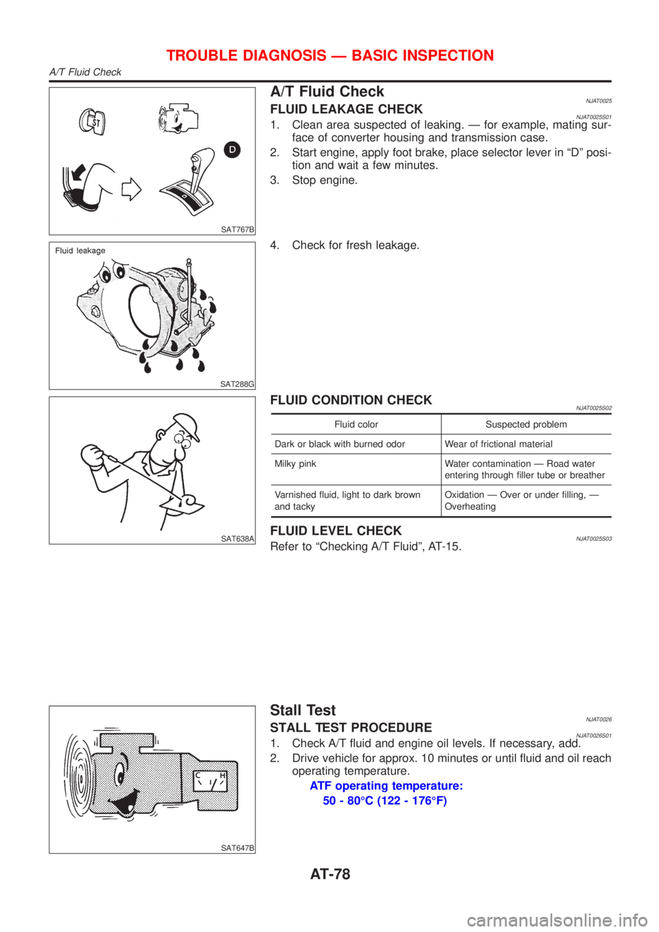
A/T Fluid CheckNJAT0025FLUID LEAKAGE CHECKNJAT0025S011. Clean area suspected of leaking. Ð for example, mating sur-
face of converter housing and transmission case.
2. Start engine, apply foot brake, place selector lever in ªDº posi-
tion and wait a few minutes.
3. Stop engine.
SAT288G
4. Check for fresh leakage.
SAT638A
FLUID CONDITION CHECKNJAT0025S02
Fluid color Suspected problem
Dark or black with burned odor Wear of frictional material
Milky pink Water contamination Ð Road water
entering through filler tube or breather
Varnished fluid, light to dark brown
and tackyOxidation Ð Over or under filling, Ð
Overheating
FLUID LEVEL CHECKNJAT0025S03Refer to ªChecking A/T Fluidº, AT-15.
SAT647B
Stall TestNJAT0026STALL TEST PROCEDURENJAT0026S011. Check A/T fluid and engine oil levels. If necessary, add.
2. Drive vehicle for approx. 10 minutes or until fluid and oil reach
operating temperature.
ATF operating temperature:
50 - 80ÉC (122 - 176ÉF)
TROUBLE DIAGNOSIS Ð BASIC INSPECTION
A/T Fluid Check
AT-78
Page 1271 of 2493
1. CHECK BEFORE ENGINE IS STARTED=NJAT0028S02
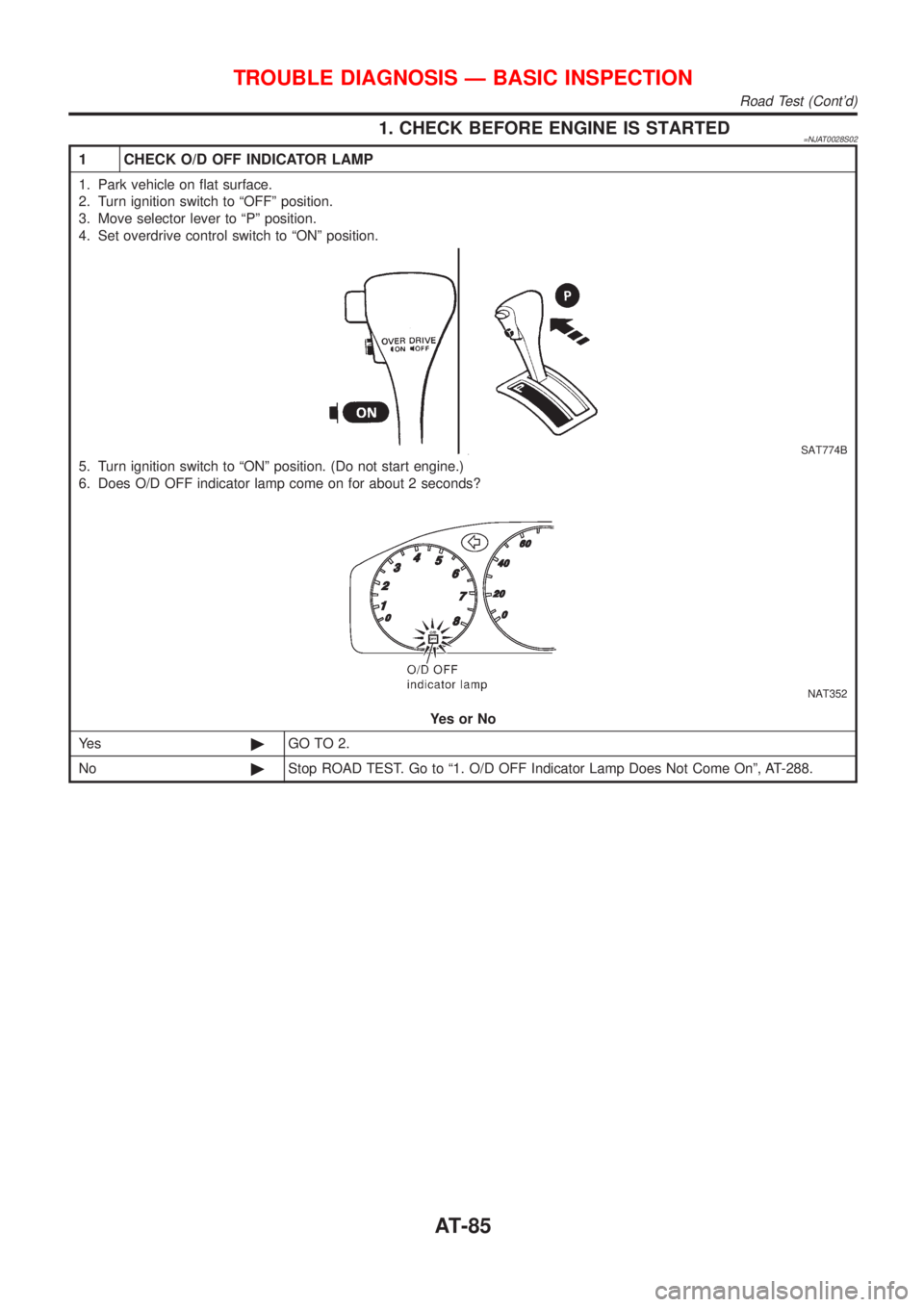
1 CHECK O/D OFF INDICATOR LAMP
1. Park vehicle on flat surface.
2. Turn ignition switch to ªOFFº position.
3. Move selector lever to ªPº position.
4. Set overdrive control switch to ªONº position.
SAT774B
5. Turn ignition switch to ªONº position. (Do not start engine.)
6. Does O/D OFF indicator lamp come on for about 2 seconds?
NAT352
YesorNo
Ye s©GO TO 2.
No©Stop ROAD TEST. Go to ª1. O/D OFF Indicator Lamp Does Not Come Onº, AT-288.
TROUBLE DIAGNOSIS Ð BASIC INSPECTION
Road Test (Cont'd)
AT-85
Page 1389 of 2493
Diagnostic trouble code Malfunction is detected when ... Check items (Possible cause)
: A/T 1ST GR FNCTN
A/T cannot be shifted to the 1st gear
position even if electrical circuit is good.+Shift solenoid valve A
+Shift solenoid valve B
+Each clutch
+Hydraulic control circuit
: P0731
SAT014K
SAT971J
SAT021J
DIAGNOSTIC TROUBLE CODE (DTC) CONFIRMATION
PROCEDURE
NJAT0279S03CAUTION:
+Always drive vehicle at a safe speed.
+Be careful not to rev engine into the red zone on the
tachometer.
NOTE:
If ªDIAGNOSTIC TROUBLE CODE CONFIRMATION PROCE-
DUREº has been previously conducted, always turn ignition
switch ªOFFº and wait at least 5 seconds before conducting
the next test.
TESTING CONDITION:
Always drive vehicle on a level road to improve the accuracy
of test.
After the repair, perform the following procedure to confirm the
malfunction is eliminated.
With CONSULT-II
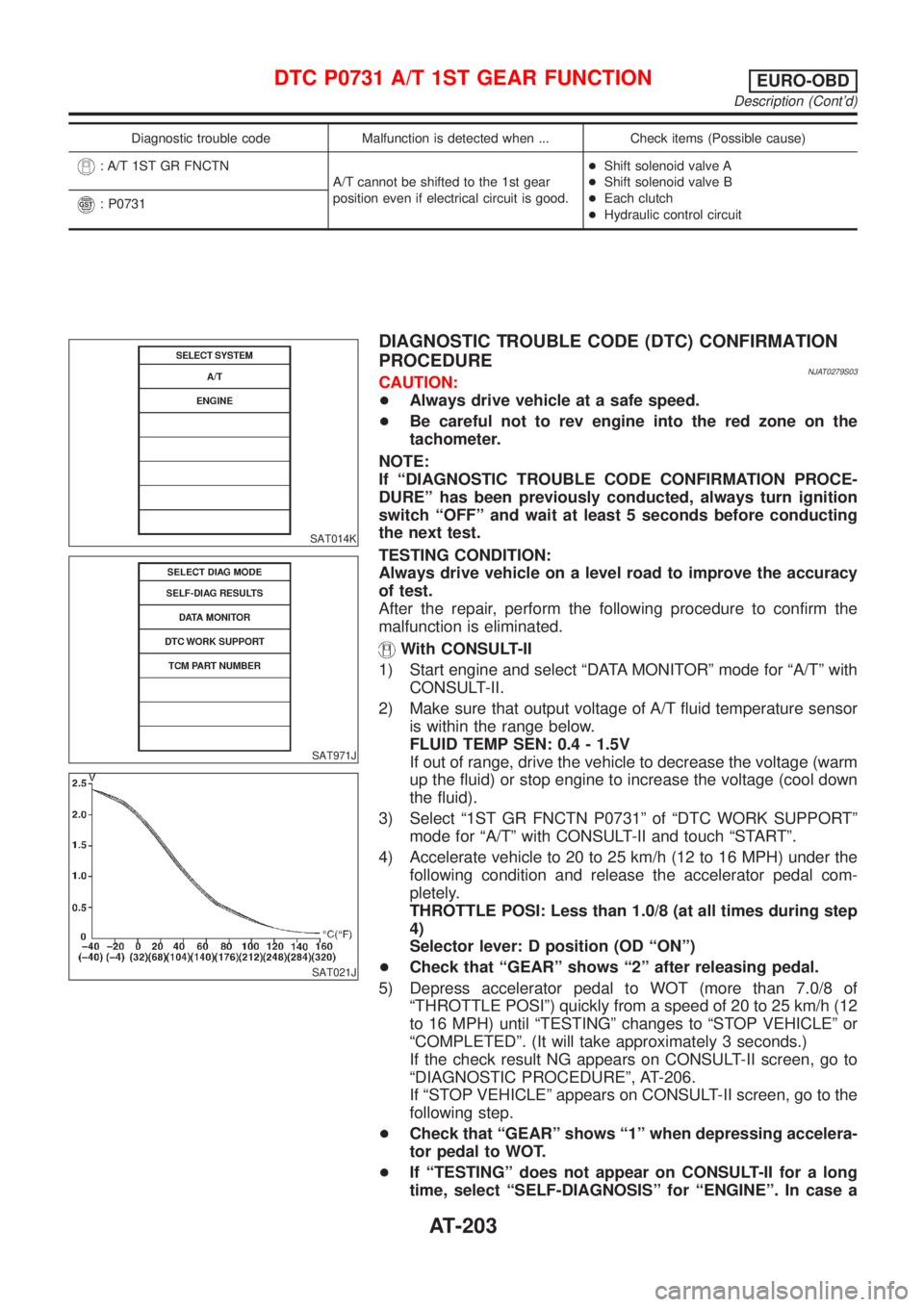
1) Start engine and select ªDATA MONITORº mode for ªA/Tº with
CONSULT-II.
2) Make sure that output voltage of A/T fluid temperature sensor
is within the range below.
FLUID TEMP SEN: 0.4 - 1.5V
If out of range, drive the vehicle to decrease the voltage (warm
up the fluid) or stop engine to increase the voltage (cool down
the fluid).
3) Select ª1ST GR FNCTN P0731º of ªDTC WORK SUPPORTº
mode for ªA/Tº with CONSULT-II and touch ªSTARTº.
4) Accelerate vehicle to 20 to 25 km/h (12 to 16 MPH) under the
following condition and release the accelerator pedal com-
pletely.
THROTTLE POSI: Less than 1.0/8 (at all times during step
4)
Selector lever: D position (OD ªONº)
+Check that ªGEARº shows ª2º after releasing pedal.
5) Depress accelerator pedal to WOT (more than 7.0/8 of
ªTHROTTLE POSIº) quickly from a speed of 20 to 25 km/h (12
to 16 MPH) until ªTESTINGº changes to ªSTOP VEHICLEº or
ªCOMPLETEDº. (It will take approximately 3 seconds.)
If the check result NG appears on CONSULT-II screen, go to
ªDIAGNOSTIC PROCEDUREº, AT-206.
If ªSTOP VEHICLEº appears on CONSULT-II screen, go to the
following step.
+Check that ªGEARº shows ª1º when depressing accelera-
tor pedal to WOT.
+If ªTESTINGº does not appear on CONSULT-II for a long
time, select ªSELF-DIAGNOSISº for ªENGINEº. In case a
DTC P0731 A/T 1ST GEAR FUNCTIONEURO-OBD
Description (Cont'd)
AT-203
Page 1396 of 2493
SAT014K
SAT971J
SAT021J
DIAGNOSTIC TROUBLE CODE (DTC) CONFIRMATION
PROCEDURE
NJAT0283S03CAUTION:
+Always drive vehicle at a safe speed.
+Be careful not to rev engine into the red zone on the
tachometer.
NOTE:
If ªDIAGNOSTIC TROUBLE CODE CONFIRMATION PROCE-
DUREº has been previously conducted, always turn ignition
switch ªOFFº and wait at least 5 seconds before conducting
the next test.
TESTING CONDITION:
Always drive vehicle on a level road to improve the accuracy
of test.
After the repair, perform the following procedure to confirm the
malfunction is eliminated.
With CONSULT-II
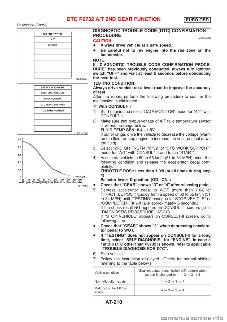
1) Start engine and select ªDATA MONITORº mode for ªA/Tº with
CONSULT-II.
2) Make sure that output voltage of A/T fluid temperature sensor
is within the range below.
FLUID TEMP SEN: 0.4 - 1.5V
If out of range, drive the vehicle to decrease the voltage (warm
up the fluid) or stop engine to increase the voltage (cool down
the fluid).
3) Select ª2ND GR FNCTN P0732º of ªDTC WORK SUPPORTº
mode for ªA/Tº with CONSULT-II and touch ªSTARTº.
4) Accelerate vehicle to 50 to 55 km/h (31 to 34 MPH) under the
following condition and release the accelerator pedal com-
pletely.
THROTTLE POSI: Less than 1.0/8 (at all times during step
4)
Selector lever: D position (OD ªONº)
+Check that ªGEARº shows ª3º or ª4º after releasing pedal.
5) Depress accelerator pedal to WOT (more than 7.0/8 of
ªTHROTTLE POSIº) quickly from a speed of 50 to 55 km/h (31
to 34 MPH) until ªTESTINGº changes to ªSTOP VEHICLEº or
ªCOMPLETEDº. (It will take approximately 3 seconds.)
If the check result NG appears on CONSULT-II screen, go to
ªDIAGNOSTIC PROCEDUREº, AT-213.
If ªSTOP VEHICLEº appears on CONSULT-II screen, go to
following step.
+Check that ªGEARº shows ª2º when depressing accelera-
tor pedal to WOT.
+If ªTESTINGº does not appear on CONSULT-II for a long
time, select ªSELF-DIAGNOSISº for ªENGINEº. In case a
1st trip DTC other than P0732 is shown, refer to applicable
ªTROUBLE DIAGNOSIS FOR DTCº.
6) Stop vehicle.
7) Follow the instruction displayed. (Check for normal shifting
referring to the table below.)
Vehicle conditionGear on actual transmission shift pattern when
screen is changed to 1®2®3®4
No malfunction exists 1®2®3®4
Malfunction for P0732
exists.4®3®3®4
DTC P0732 A/T 2ND GEAR FUNCTIONEURO-OBD
Description (Cont'd)
AT-210