battery replacement NISSAN ALMERA N16 2001 Electronic Repair Manual
[x] Cancel search | Manufacturer: NISSAN, Model Year: 2001, Model line: ALMERA N16, Model: NISSAN ALMERA N16 2001Pages: 2493, PDF Size: 66.97 MB
Page 3 of 2493
GENERAL INFORMATION
SECTION
GI
CONTENTS
PRECAUTIONS...............................................................3
Precautions ..................................................................3
PRECAUTIONS FOR SUPPLEMENTAL
RESTRAINT SYSTEM (SRS)²AIR BAG²AND
²SEAT BELT PRE-TENSIONER²
.................................3
PRECAUTIONS FOR NATS (NISSAN ANTI-THEFT
SYSTEM)
..................................................................3
GENERAL PRECAUTIONS.........................................4
PRECAUTIONS FOR MULTIPORT FUEL
INJECTION SYSTEM OR ENGINE CONTROL
SYSTEM
...................................................................6
PRECAUTIONS FOR THREE WAY CATALYST...........6
PRECAUTIONS FOR HOSES.....................................6
PRECAUTIONS FOR ENGINE OILS...........................7
PRECAUTIONS FOR FUEL........................................8
PRECAUTIONS FOR AIR CONDITIONING..................9
HOW TO USE THIS MANUAL......................................10
HOW TO READ WIRING DIAGRAMS..........................12
Sample/Wiring Diagram - EXAMPL - ........................12
OPTIONAL SPLICE..................................................13
Description .................................................................14
CONNECTOR SYMBOLS.........................................16
HARNESS INDICATION...........................................17
COMPONENT INDICATION......................................17
SWITCH POSITIONS...............................................17
DETECTABLE LINES AND NON-DETECTABLE
LINES
.....................................................................17
MULTIPLE SWITCH.................................................18
REFERENCE AREA.................................................19
HOW TO PERFORM EFFICIENT DIAGNOSES
FOR AN ELECTRICAL INCIDENT...............................21
Work Flow ..................................................................21
Incident Simulation Tests ...........................................22
INTRODUCTION......................................................22
VEHICLE VIBRATION..............................................22
HEAT SENSITIVE....................................................23
FREEZING..............................................................23
WATER INTRUSION................................................24
ELECTRICAL LOAD.................................................24
COLD OR HOT START UP.......................................24
Circuit Inspection .......................................................24
INTRODUCTION......................................................24
TESTING FOR²OPENS²IN THE CIRCUIT................25
TESTING FOR²SHORTS²IN THE CIRCUIT..............26
GROUND INSPECTION...........................................27
VOLTAGE DROP TESTS..........................................27
CONTROL UNIT CIRCUIT TEST...............................29
HOW TO FOLLOW TROUBLE DIAGNOSES...............31
How to Follow Test Groups in Trouble Diagnoses ....32
Key to Symbols Signifying Measurements or
Procedures.................................................................33
CONSULT-II CHECKING SYSTEM...............................35
Function and System Application ..............................35
Nickel Metal Hydride Battery Replacement...............36
Checking Equipment..................................................36
CONSULT-II Data Link Connector (DLC) Circuit ......37
INSPECTION PROCEDURE.....................................37
IDENTIFICATION INFORMATION................................38
Model Variation ..........................................................38
FOR EUROPE.........................................................38
FOR AUSTRALIA, NEW ZEALAND AND SOUTH
AFRICA
...................................................................38
PREFIX AND SUFFIX DESIGNATIONS.....................39
Identification Number .................................................39
VEHICLE IDENTIFICATION NUMBER
ARRANGEMENT
.....................................................40
IDENTIFICATION PLATE..........................................40
ENGINE SERIAL NUMBER.......................................41
AUTOMATIC TRANSAXLE NUMBER........................41
MANUAL TRANSAXLE NUMBER..............................42
Dimensions ................................................................43
Wheels and Tires .......................................................43
LIFTING POINTS AND TOW TRUCK TOWING...........44
Preparation ................................................................44
SPECIAL SERVICE TOOLS......................................44
Board-on Lift ..............................................................44
Garage Jack and Safety Stand .................................45
2-pole Lift ...................................................................46
Tow Truck Towing ......................................................47
TOWING AN AUTOMATIC TRANSAXLE MODEL
WITH FOUR WHEELS ON GROUND
........................47
Page 38 of 2493
Nickel Metal Hydride Battery Replacement=NJGI0007S06CONSULT-II contains a nickel metal hydride battery. When replacing the battery obey the following:
WARNING:
Replace the nickel metal hydride battery with Genuine CONSULT-II battery only. Use of another bat-
tery may present a risk of fire or explosion. The battery may present a fire or chemical burn hazard if
mistreated. Do not recharge, disassemble of dispose of in fire.
Keep the battery out of reach of children and discard used battery conforming to the local regulations.
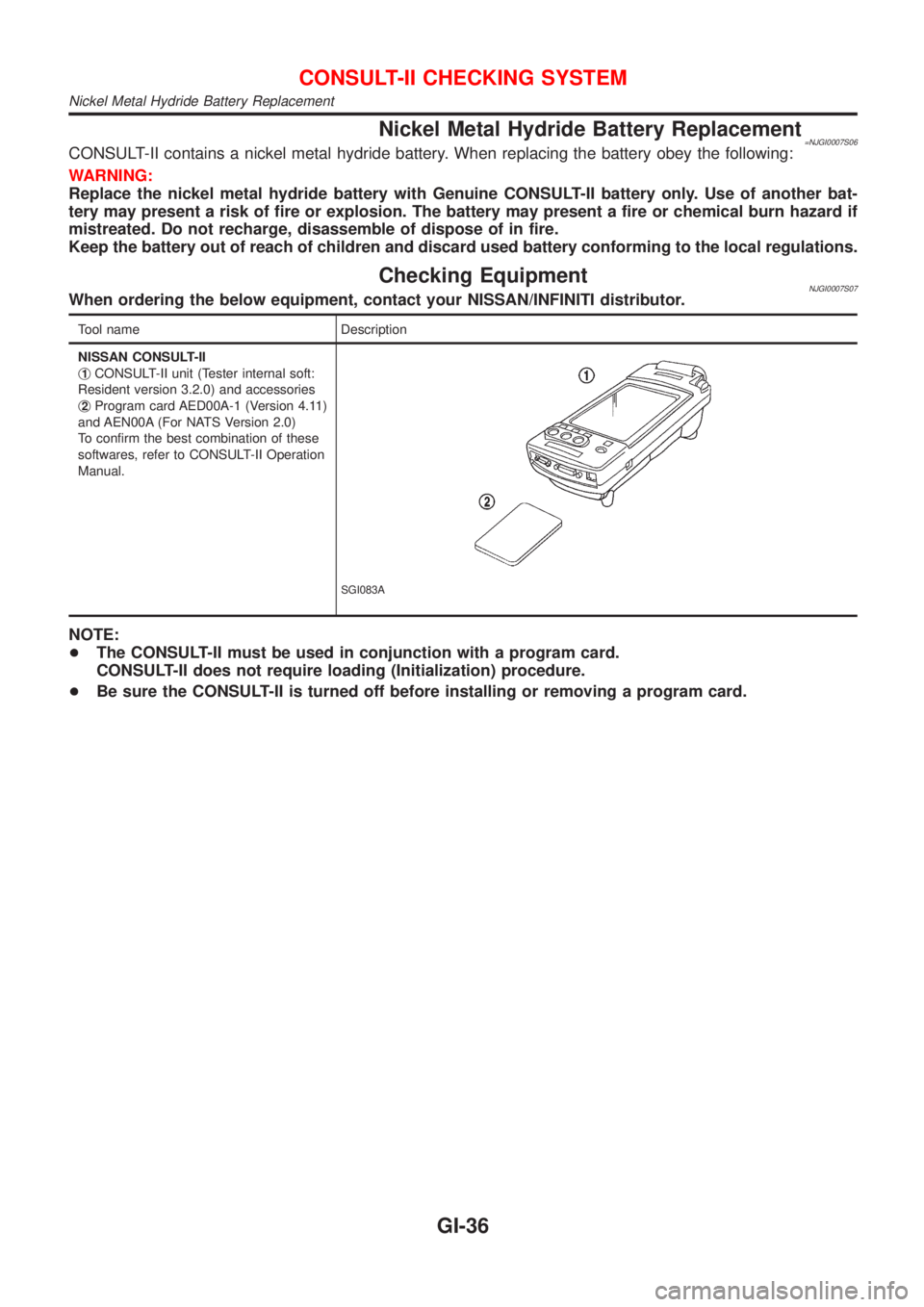
Checking EquipmentNJGI0007S07When ordering the below equipment, contact your NISSAN/INFINITI distributor.
Tool name Description
NISSAN CONSULT-II
j
1CONSULT-II unit (Tester internal soft:
Resident version 3.2.0) and accessories
j
2Program card AED00A-1 (Version 4.11)
and AEN00A (For NATS Version 2.0)
To confirm the best combination of these
softwares, refer to CONSULT-II Operation
Manual.
SGI083A
NOTE:
+The CONSULT-II must be used in conjunction with a program card.
CONSULT-II does not require loading (Initialization) procedure.
+Be sure the CONSULT-II is turned off before installing or removing a program card.
CONSULT-II CHECKING SYSTEM
Nickel Metal Hydride Battery Replacement
GI-36
Page 1846 of 2493
Diagnosis Sensor Unit
REMOVAL AND INSTALLATIONNJRS0013CAUTION:
+Before servicing SRS, turn the ignition switch off, discon-
nect both battery cables and wait at least 3 minutes.
+The special bolts are coated with bonding agent while the
other bolt is for ground. Do not use old bolts after
removal; replace with new ones.
+Check diagnosis sensor unit for proper installation.
+Check diagnosis sensor unit to ensure it is free of
deformities, dents, cracks or rust. If they show any visible
signs of damage, replace them with new ones.
+Check diagnosis sensor unit brackets to ensure they are
free of deformities or rust.
+Replace diagnosis sensor unit if it has been dropped or
sustained an impact.
+After replacement of diagnosis sensor unit, perform self-
diagnosis for SRS. Refer to ªSRS Operation Checkº for
details. (RS-49)
SRS964
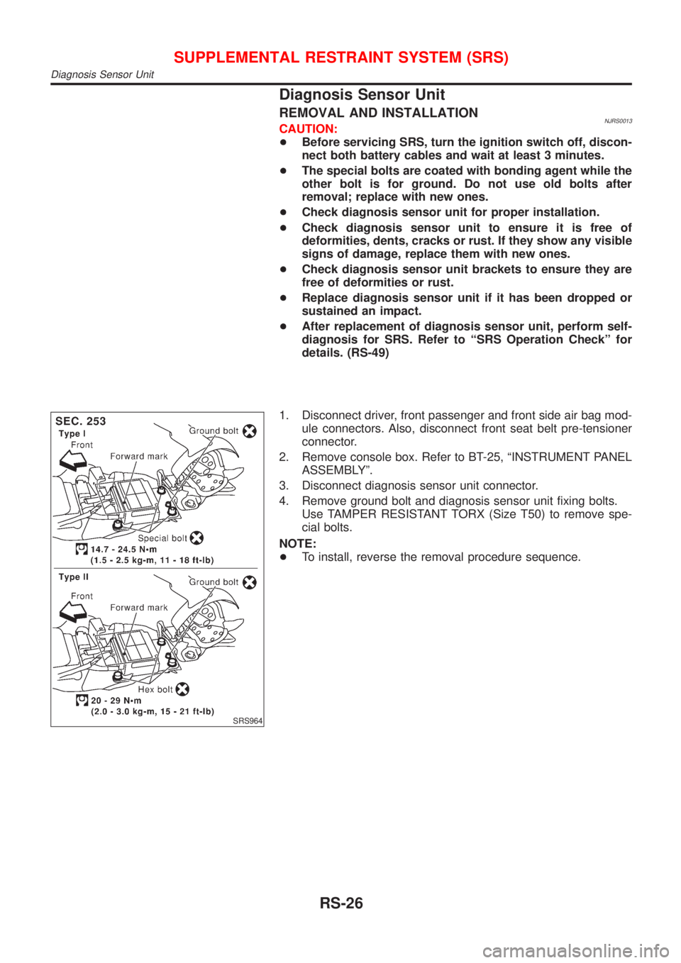
1. Disconnect driver, front passenger and front side air bag mod-
ule connectors. Also, disconnect front seat belt pre-tensioner
connector.
2. Remove console box. Refer to BT-25, ªINSTRUMENT PANEL
ASSEMBLYº.
3. Disconnect diagnosis sensor unit connector.
4. Remove ground bolt and diagnosis sensor unit fixing bolts.
Use TAMPER RESISTANT TORX (Size T50) to remove spe-
cial bolts.
NOTE:
+To install, reverse the removal procedure sequence.
SUPPLEMENTAL RESTRAINT SYSTEM (SRS)
Diagnosis Sensor Unit
RS-26
Page 1847 of 2493
SRS563-D
SRS863
Front Seat Belt Pre-tensioner
REMOVAL AND INSTALLATIONNJRS0036CAUTION:
+Before servicing SRS, turn the ignition switch off, discon-
nect both battery cables and wait at least 3 minutes.
+Check front seat front belt pre-tensioner with load limiter
for proper installation.
+After replacement of front seat belt pre-tensioner, check
SRS function and perform self-diagnosis for SRS.
Refer to ªSRS Operation Checkº for details. (RS-49)
+Do not attempt to disassemble front seat belt pre-ten-
sioner with load limiter.
+Replace front seat belt pre-tensioner if it has been
dropped or sustained an impact.
+Do not expose front seat belt pre-tensioner to tempera-
tures exceeding 80ÉC (176ÉF).
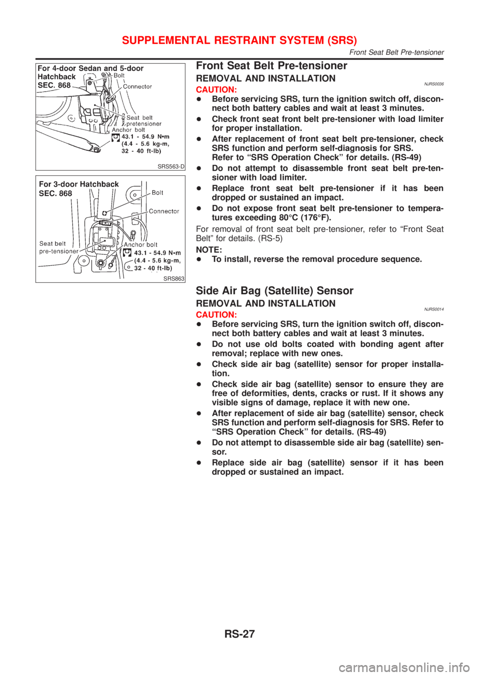
For removal of front seat belt pre-tensioner, refer to ªFront Seat
Beltº for details. (RS-5)
NOTE:
+To install, reverse the removal procedure sequence.
Side Air Bag (Satellite) Sensor
REMOVAL AND INSTALLATIONNJRS0014CAUTION:
+Before servicing SRS, turn the ignition switch off, discon-
nect both battery cables and wait at least 3 minutes.
+Do not use old bolts coated with bonding agent after
removal; replace with new ones.
+Check side air bag (satellite) sensor for proper installa-
tion.
+Check side air bag (satellite) sensor to ensure they are
free of deformities, dents, cracks or rust. If it shows any
visible signs of damage, replace it with new one.
+After replacement of side air bag (satellite) sensor, check
SRS function and perform self-diagnosis for SRS. Refer to
ªSRS Operation Checkº for details. (RS-49)
+Do not attempt to disassemble side air bag (satellite) sen-
sor.
+Replace side air bag (satellite) sensor if it has been
dropped or sustained an impact.
SUPPLEMENTAL RESTRAINT SYSTEM (SRS)
Front Seat Belt Pre-tensioner
RS-27
Page 1871 of 2493
![NISSAN ALMERA N16 2001 Electronic Repair Manual SRS772
7. Diagnostic codes are displayed on ªSELF-DIAG [CURRENT]º.
SRS701
If no malfunction is detected on ªSELF-DIAG [CURRENT]º but mal-
function is indicated by the ªAIR BAGº warning lamp, go](/img/5/57351/w960_57351-1870.png "NISSAN ALMERA N16 2001 Electronic Repair Manual SRS772
7. Diagnostic codes are displayed on ªSELF-DIAG [CURRENT]º.
SRS701
If no malfunction is detected on ªSELF-DIAG [CURRENT]º but mal-
function is indicated by the ªAIR BAGº warning lamp, go")
SRS772
7. Diagnostic codes are displayed on ªSELF-DIAG [CURRENT]º.
SRS701
If no malfunction is detected on ªSELF-DIAG [CURRENT]º but mal-
function is indicated by the ªAIR BAGº warning lamp, go to DIAG-
NOSTIC PROCEDURE 4, page RS-56, to diagnose the following
situations:
+Self-diagnostic result ªSELF-DIAG [PAST]º (previously stored
in the memory) might not be erased after repair.
+The SRS system malfunctions intermittently.
8. Touch ªPRINTº.
9. Compare diagnostic codes to ªCONSULT-II Diagnostic Code
Chartº, RS-51.
10. Touch ªBACKº key of CONSULT-II until ªSELECT SYSTEMº
appears in order to return to User mode from Diagnosis mode.
11. Turn ignition switch ªOFFº, then turn off and disconnect
CONSULT-II, and disconnect both battery cables.
12. Repair the system as outlined by the ªRepair orderº in ªCON-
SULT-II Diagnostic Code Chartº, that corresponds to the self-
diagnostic result. For replacement procedure of component
parts, refer to RS-26.
13. After repairing the system, go to DIAGNOSTIC PROCEDURE
3, page RS-54 for final checking.
CONSULT-II DIAGNOSTIC CODE CHART (ªSELF-DIAG
[CURRENT]º)
NJRS0048S0102
Diagnostic item ExplanationRepair order
Recheck SRS at each
replacement.
NO DTC IS DETECTED When malfunction is indicated
by the ªAIR BAGº warning
lamp in User mode+Self-diagnostic result ªSELF-
DIAG [PAST]º (previously
stored in the memory) might
not be erased after repair.
+Intermittent malfunction has
been detected in the past.+Go to DIAGNOSTIC PRO-
CEDURE 3 (RS-54).
+No malfunction is detected.+Go to DIAGNOSTIC PRO-
CEDURE 3 (RS-54).
SUPPLEMENTAL RESTRAINT SYSTEM (SRS)
Trouble Diagnoses with CONSULT-II (Cont'd)
RS-51
Page 1873 of 2493
![NISSAN ALMERA N16 2001 Electronic Repair Manual Diagnostic item ExplanationRepair order
Recheck SRS at each
replacement.
SATELLITE SENS RH
[UNIT FAIL]
SATELLITE SENS RH
[COMM FAIL]+RH side air bag (satellite) sensor 1. Visually check the wiring
har](/img/5/57351/w960_57351-1872.png "NISSAN ALMERA N16 2001 Electronic Repair Manual Diagnostic item ExplanationRepair order
Recheck SRS at each
replacement.
SATELLITE SENS RH
[UNIT FAIL]
SATELLITE SENS RH
[COMM FAIL]+RH side air bag (satellite) sensor 1. Visually check the wiring
har")
Diagnostic item ExplanationRepair order
Recheck SRS at each
replacement.
SATELLITE SENS RH
[UNIT FAIL]
SATELLITE SENS RH
[COMM FAIL]+RH side air bag (satellite) sensor 1. Visually check the wiring
harness connection.
2. Replace the harness if it
has visible damage.
3. Replace the RH side air
bag (satellite) sensor.
4. Replace the diagnosis sen-
sor unit.
5. Replace the related har-
ness.
PRE-TEN FRONT LH
[OPEN/VB-SHORT]+The circuit for the front LH pre-tensioner is open or shorted
to a power supply circuit.1. Visually check the wiring
harness connections.
2. Replace the harness if it
has visible damage.
3. Replace the front LH seat
belt.
(Before disposal, it must be
deactivated.)
4. Replace the diagnosis sen-
sor unit.
5. Replace the related har-
ness. PRE-TEN FRONT LH
[GND-SHORT]+The circuit for the front LH pre-tensioner is shorted to
ground.
PRE-TEN FRONT RH
[OPEN/VB-SHORT]+The circuit for the front RH pre-tensioner is open or shorted
to a power supply circuit.1. Visually check the wiring
harness connections.
2. Replace the harness if it
has visible damage.
3. Replace the front RH seat
belt.
(Before disposal, it must be
deactivated.)
4. Replace the diagnosis sen-
sor unit.
5. Replace the related har-
ness. PRE-TEN FRONT RH
[GND-SHORT]+The circuit for the front RH pre-tensioner is shorted to
ground.
CONTROL UNIT+Low battery voltage (Less than 9V)+Go to DIAGNOSTIC PRO-
CEDURE 3 (RS-54) after
charging battery.
+Diagnosis sensor unit is malfunctioning. 1. Visually check wiring har-
ness connections.
2. Replace the harness if it
has visible damage.
3. Replace diagnosis sensor
unit.
4. Replace the related har-
ness.
* Follow the procedures in numerical order when repairing malfunctioning parts. Confirm whether malfunction is eliminated
using the air bag or seat belt warning lamp or CONSULT-II each time repair is finished. If malfunction is still observed, pro-
ceed to the next step. When malfunction is eliminated, further repair work is not required.
SUPPLEMENTAL RESTRAINT SYSTEM (SRS)
Trouble Diagnoses with CONSULT-II (Cont'd)
RS-53
Page 1878 of 2493
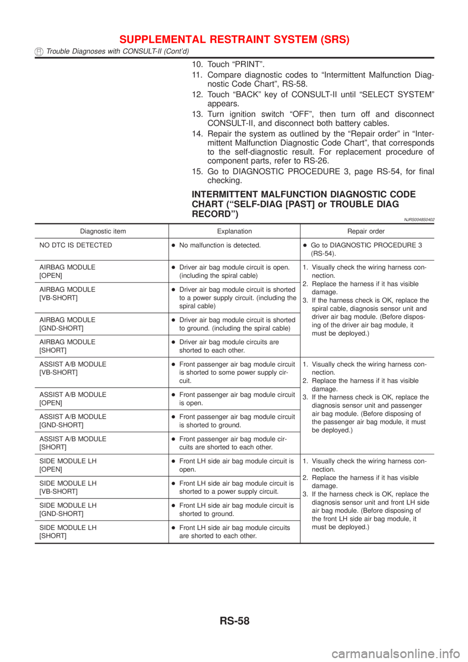
10. Touch ªPRINTº.
11. Compare diagnostic codes to ªIntermittent Malfunction Diag-
nostic Code Chartº, RS-58.
12. Touch ªBACKº key of CONSULT-II until ªSELECT SYSTEMº
appears.
13. Turn ignition switch ªOFFº, then turn off and disconnect
CONSULT-II, and disconnect both battery cables.
14. Repair the system as outlined by the ªRepair orderº in ªInter-
mittent Malfunction Diagnostic Code Chartº, that corresponds
to the self-diagnostic result. For replacement procedure of
component parts, refer to RS-26.
15. Go to DIAGNOSTIC PROCEDURE 3, page RS-54, for final
checking.
INTERMITTENT MALFUNCTION DIAGNOSTIC CODE
CHART (ªSELF-DIAG [PAST] or TROUBLE DIAG
RECORDº)
NJRS0048S0402
Diagnostic item Explanation Repair order
NO DTC IS DETECTED+No malfunction is detected.+Go to DIAGNOSTIC PROCEDURE 3
(RS-54).
AIRBAG MODULE
[OPEN]+Driver air bag module circuit is open.
(including the spiral cable)1. Visually check the wiring harness con-
nection.
2. Replace the harness if it has visible
damage.
3. If the harness check is OK, replace the
spiral cable, diagnosis sensor unit and
driver air bag module. (Before dispos-
ing of the driver air bag module, it
must be deployed.) AIRBAG MODULE
[VB-SHORT]+Driver air bag module circuit is shorted
to a power supply circuit. (including the
spiral cable)
AIRBAG MODULE
[GND-SHORT]+Driver air bag module circuit is shorted
to ground. (including the spiral cable)
AIRBAG MODULE
[SHORT]+Driver air bag module circuits are
shorted to each other.
ASSIST A/B MODULE
[VB-SHORT]+Front passenger air bag module circuit
is shorted to some power supply cir-
cuit.1. Visually check the wiring harness con-
nection.
2. Replace the harness if it has visible
damage.
3. If the harness check is OK, replace the
diagnosis sensor unit and passenger
air bag module. (Before disposing of
the passenger air bag module, it must
be deployed.) ASSIST A/B MODULE
[OPEN]+Front passenger air bag module circuit
is open.
ASSIST A/B MODULE
[GND-SHORT]+Front passenger air bag module circuit
is shorted to ground.
ASSIST A/B MODULE
[SHORT]+Front passenger air bag module cir-
cuits are shorted to each other.
SIDE MODULE LH
[OPEN]+Front LH side air bag module circuit is
open.1. Visually check the wiring harness con-
nection.
2. Replace the harness if it has visible
damage.
3. If the harness check is OK, replace the
diagnosis sensor unit and front LH side
air bag module. (Before disposing of
the front LH side air bag module, it
must be deployed.) SIDE MODULE LH
[VB-SHORT]+Front LH side air bag module circuit is
shorted to a power supply circuit.
SIDE MODULE LH
[GND-SHORT]+Front LH side air bag module circuit is
shorted to ground.
SIDE MODULE LH
[SHORT]+Front LH side air bag module circuits
are shorted to each other.
SUPPLEMENTAL RESTRAINT SYSTEM (SRS)
Trouble Diagnoses with CONSULT-II (Cont'd)
RS-58
Page 1881 of 2493
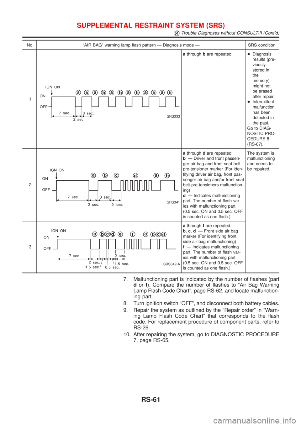
No. ªAIR BAGº warning lamp flash pattern Ð Diagnosis mode Ð SRS condition
1
SRS333
athroughbare repeated.+Diagnosis
results (pre-
viously
stored in
the
memory)
might not
be erased
after repair.
+Intermittent
malfunction
has been
detected in
the past.
Go to DIAG-
NOSTIC PRO-
CEDURE 8
(RS-67).
2
SRS341
athroughdare repeated.
bÐ Driver and front passen-
ger air bag and front seat belt
pre-tensioner marker (For iden-
tifying driver air bag, front pas-
senger air bag and/or front seat
belt pre-tensioners malfunction-
ing)
dÐ Indicates malfunctioning
part. The number of flash var-
ies with malfunctioning part
(0.5 sec. ON and 0.5 sec. OFF
is counted as one flash.)The system is
malfunctioning
and needs to
be repaired.
3
SRS342-A
athroughfare repeated.
b,c,dÐ Front side air bag
marker (For identifying front
side air bag malfunctioning)
fÐ Indicates malfunctioning
part. The number of flash var-
ies with malfunctioning part
(0.5 sec. ON and 0.5 sec. OFF
is counted as one flash.)
7. Malfunctioning part is indicated by the number of flashes (part
dorf). Compare the number of flashes to ªAir Bag Warning
Lamp Flash Code Chartº, page RS-62, and locate malfunction-
ing part.
8. Turn ignition switch ªOFFº, and disconnect both battery cables.
9. Repair the system as outlined by the ªRepair orderº in ªWarn-
ing Lamp Flash Code Chartº that corresponds to the flash
code. For replacement procedure of component parts, refer to
RS-26.
10. After repairing the system, go to DIAGNOSTIC PROCEDURE
7, page RS-65.
SUPPLEMENTAL RESTRAINT SYSTEM (SRS)
Trouble Diagnoses without CONSULT-II (Cont'd)
RS-61
Page 1885 of 2493
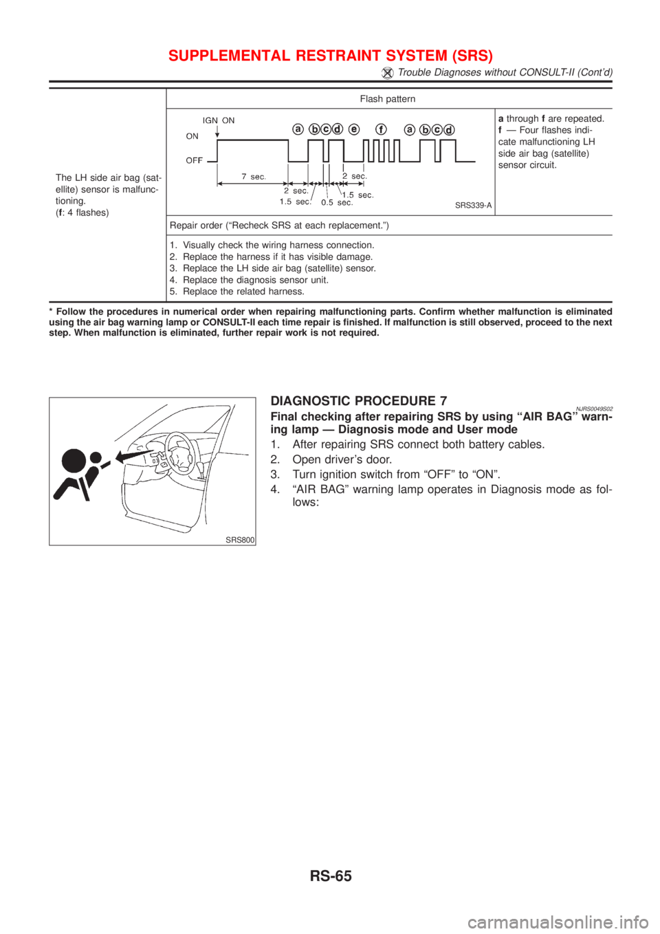
The LH side air bag (sat-
ellite) sensor is malfunc-
tioning.
(f: 4 flashes)Flash pattern
SRS339-A
athroughfare repeated.
fÐ Four flashes indi-
cate malfunctioning LH
side air bag (satellite)
sensor circuit.
Repair order (ªRecheck SRS at each replacement.º)
1. Visually check the wiring harness connection.
2. Replace the harness if it has visible damage.
3. Replace the LH side air bag (satellite) sensor.
4. Replace the diagnosis sensor unit.
5. Replace the related harness.
* Follow the procedures in numerical order when repairing malfunctioning parts. Confirm whether malfunction is eliminated
using the air bag warning lamp or CONSULT-II each time repair is finished. If malfunction is still observed, proceed to the next
step. When malfunction is eliminated, further repair work is not required.
SRS800
DIAGNOSTIC PROCEDURE 7NJRS0049S02Final checking after repairing SRS by using ªAIR BAGº warn-
ing lamp Ð Diagnosis mode and User mode
1. After repairing SRS connect both battery cables.
2. Open driver's door.
3. Turn ignition switch from ªOFFº to ªONº.
4. ªAIR BAGº warning lamp operates in Diagnosis mode as fol-
lows:
SUPPLEMENTAL RESTRAINT SYSTEM (SRS)
Trouble Diagnoses without CONSULT-II (Cont'd)
RS-65
Page 2114 of 2493
WARNING CHIME....................................................... 113
Component Parts and Harness Connector
Location ................................................................... 113
System Description .................................................. 113
Wiring Diagram - CHIME - ...................................... 115
Trouble Diagnoses................................................... 117
FRONT WIPER AND WASHER..................................123
System Description ..................................................123
Wiring Diagram - WIPER - ......................................125
Removal and Installation .........................................127
Washer Nozzle Adjustment .....................................128
Washer Tube Layout ...............................................128
REAR WIPER AND WASHER....................................129
Wiring Diagram - WIP/R -........................................129
Removal and Installation .........................................131
Washer Nozzle Adjustment .....................................131
Washer Tube Layout ...............................................132
HEADLAMP WASHER................................................133
Wiring Diagram - HLC - ...........................................133
Washer Tube Layout ...............................................134
HORN...........................................................................135
Wiring Diagram - HORN - .......................................135
CIGARETTE LIGHTER................................................136
Wiring Diagram - CIGAR -.......................................136
CLOCK.........................................................................137
Wiring Diagram - CLOCK -......................................137
REAR WINDOW DEFOGGER.....................................138
System Description ..................................................138
Schematic ................................................................139
Wiring Diagram - DEF - ...........................................140
Trouble Diagnoses...................................................143
Electrical Components Inspection ...........................146
Filament Check ........................................................147
Filament Repair .......................................................148
AUDIO..........................................................................149
System Description ..................................................149
Schematic ................................................................151
Wiring Diagram - AUDIO - .......................................152
Trouble Diagnoses...................................................160
Inspection.................................................................161
AUDIO ANTENNA.......................................................162
Location of Antenna .................................................162
Antenna Rod Replacement .....................................162
HEATED SEAT............................................................163
Wiring Diagram - H/SEAT - .....................................163
POWER SUNROOF.....................................................165
Wiring Diagram - SROOF - .....................................165
Trouble Diagnoses...................................................166
DOOR MIRROR...........................................................167
Wiring Diagram - MIRROR - ...................................167
POWER WINDOW.......................................................169
System Description ..................................................169Schematic ................................................................171
Wiring Diagram - WINDOW - ..................................172
Trouble Diagnoses...................................................176
POWER DOOR LOCK.................................................177
System Description ..................................................177
Schematic ................................................................178
Wiring Diagram - D/LOCK -.....................................180
Trouble Diagnoses...................................................187
POWER DOOR LOCK - SUPER LOCK -...................196
System Description ..................................................196
Schematic ................................................................198
Wiring Diagram - S/LOCK - .....................................200
Trouble Diagnoses...................................................207
MULTI-REMOTE CONTROL SYSTEM.......................220
System Description ..................................................220
Wiring Diagram - MULTI - .......................................221
Trouble Diagnoses...................................................223
ID Code Entry Procedure ........................................227
Remote Controller Battery Replacement.................228
TIME CONTROL UNIT................................................229
Description ...............................................................229
Trouble Diagnoses...................................................230
Schematic ................................................................232
NATS (NISSAN ANTI-THEFT SYSTEM).....................234
Component Parts and Harness Connetor
Location ...................................................................234
System Description ..................................................234
System Composition ................................................236
Wiring Diagram - NATS -.........................................237
CONSULT-II .............................................................238
Trouble Diagnoses...................................................241
How to Replace NATS IMMU ..................................258
NAVIGATION SYSTEM...............................................259
Precautions ..............................................................259
Component Parts Location ......................................260
System Description ..................................................261
Schematic ................................................................269
Wiring Diagram - NAVI - ..........................................270
Self-diagnosis Mode ................................................278
Confirmation/Adjustment Mode ...............................281
Control Panel Mode .................................................293
Guide Volume Setting ..............................................300
Anti-theft System .....................................................301
CONSULT-II .............................................................302
Trouble Diagnoses...................................................303
This Condition Is Not Abnormal...............................309
Program Loading .....................................................318
ELECTRICAL UNITS LOCATION...............................319
Engine Compartment ...............................................319
Passenger Compartment/LHD Models ....................320
Passenger Compartment/RHD Models ...................322
CONTENTS(Cont'd)
EL-2