brakes NISSAN ALMERA N16 2001 Electronic Repair Manual
[x] Cancel search | Manufacturer: NISSAN, Model Year: 2001, Model line: ALMERA N16, Model: NISSAN ALMERA N16 2001Pages: 2493, PDF Size: 66.97 MB
Page 272 of 2493
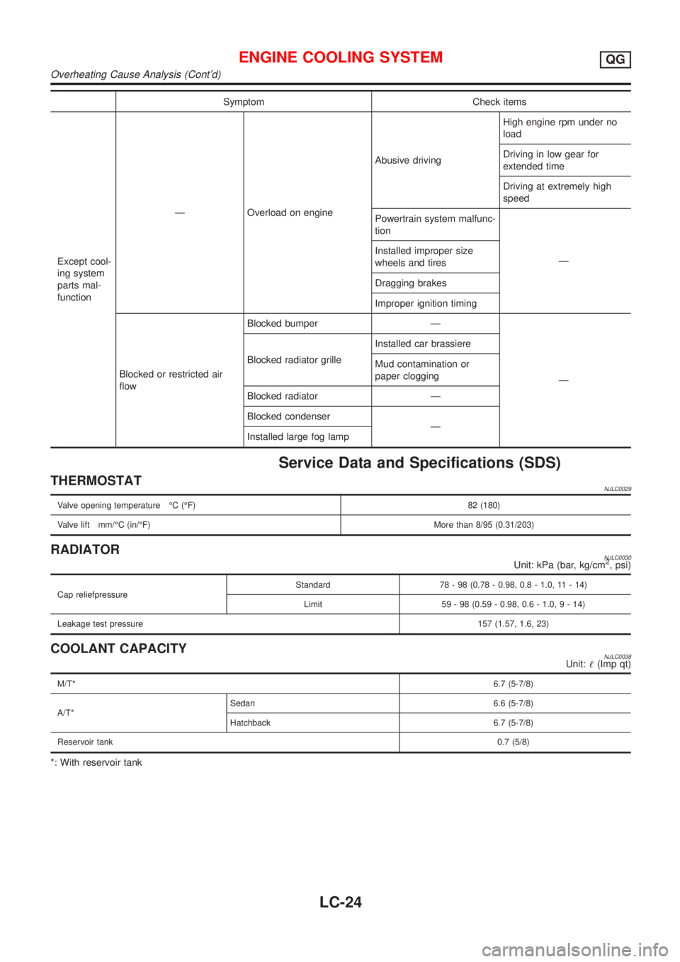
Symptom Check items
Except cool-
ing system
parts mal-
functionÐ Overload on engineAbusive drivingHigh engine rpm under no
load
Driving in low gear for
extended time
Driving at extremely high
speed
Powertrain system malfunc-
tion
Ð Installed improper size
wheels and tires
Dragging brakes
Improper ignition timing
Blocked or restricted air
flowBlocked bumper Ð
Ð Blocked radiator grilleInstalled car brassiere
Mud contamination or
paper clogging
Blocked radiator Ð
Blocked condenser
Ð
Installed large fog lamp
Service Data and Specifications (SDS)
THERMOSTATNJLC0029
Valve opening temperature ÉC (ÉF) 82 (180)
Valve lift mm/ÉC (in/ÉF)More than 8/95 (0.31/203)
RADIATORNJLC0030Unit: kPa (bar, kg/cm2, psi)
Cap reliefpressureStandard 78 - 98 (0.78 - 0.98, 0.8 - 1.0, 11 - 14)
Limit 59 - 98 (0.59 - 0.98, 0.6 - 1.0,9-14)
Leakage test pressure157 (1.57, 1.6, 23)
COOLANT CAPACITYNJLC0038Unit:!(Imp qt)
M/T*6.7 (5-7/8)
A/T*Sedan 6.6 (5-7/8)
Hatchback 6.7 (5-7/8)
Reservoir tank0.7 (5/8)
*: With reservoir tank
ENGINE COOLING SYSTEMQG
Overheating Cause Analysis (Cont'd)
LC-24
Page 295 of 2493
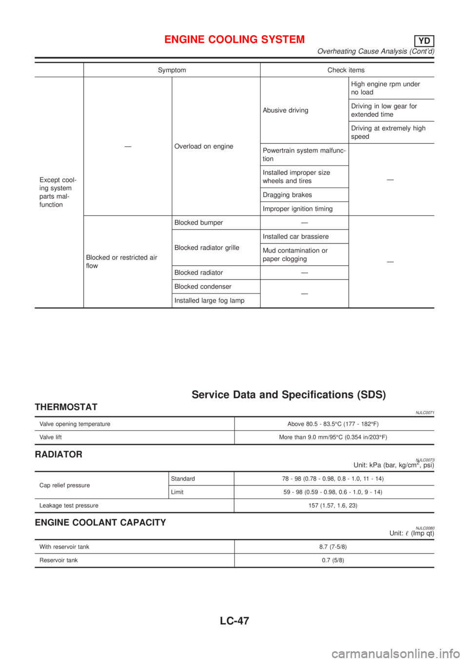
Symptom Check items
Except cool-
ing system
parts mal-
functionÐ Overload on engineAbusive drivingHigh engine rpm under
no load
Driving in low gear for
extended time
Driving at extremely high
speed
Powertrain system malfunc-
tion
Ð Installed improper size
wheels and tires
Dragging brakes
Improper ignition timing
Blocked or restricted air
flowBlocked bumper Ð
Ð Blocked radiator grilleInstalled car brassiere
Mud contamination or
paper clogging
Blocked radiator Ð
Blocked condenser
Ð
Installed large fog lamp
Service Data and Specifications (SDS)
THERMOSTATNJLC0071
Valve opening temperature Above 80.5 - 83.5ÉC (177 - 182ÉF)
Valve liftMore than 9.0 mm/95ÉC (0.354 in/203ÉF)
RADIATORNJLC0073Unit: kPa (bar, kg/cm2, psi)
Cap relief pressureStandard 78 - 98 (0.78 - 0.98, 0.8 - 1.0, 11 - 14)
Limit 59 - 98 (0.59 - 0.98, 0.6 - 1.0,9-14)
Leakage test pressure157 (1.57, 1.6, 23)
ENGINE COOLANT CAPACITYNJLC0080Unit:!(Imp qt)
With reservoir tank8.7 (7-5/8)
Reservoir tank0.7 (5/8)
ENGINE COOLING SYSTEMYD
Overheating Cause Analysis (Cont'd)
LC-47
Page 1190 of 2493
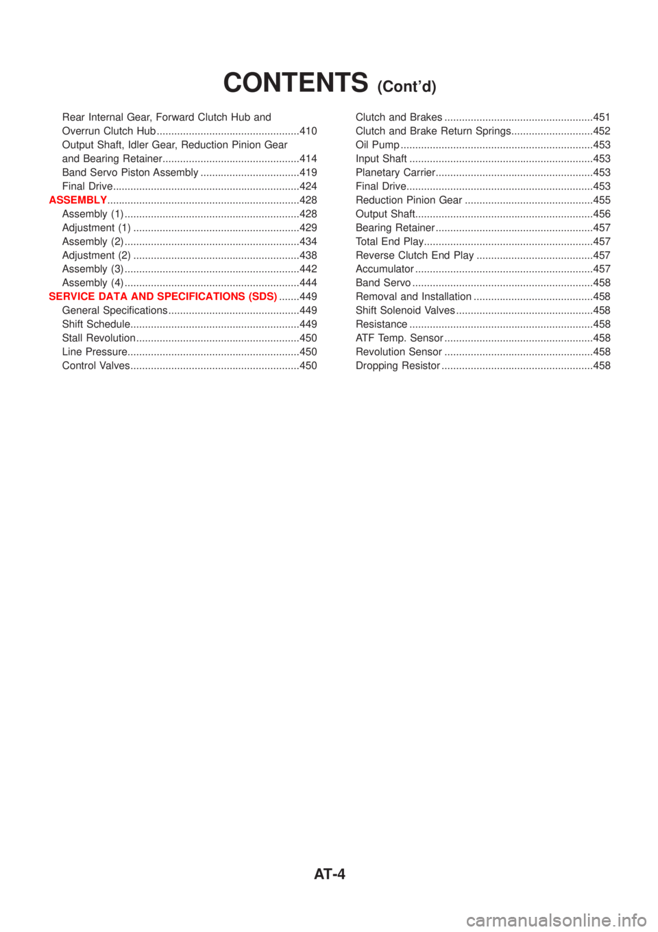
Rear Internal Gear, Forward Clutch Hub and
Overrun Clutch Hub .................................................410
Output Shaft, Idler Gear, Reduction Pinion Gear
and Bearing Retainer...............................................414
Band Servo Piston Assembly ..................................419
Final Drive................................................................424
ASSEMBLY..................................................................428
Assembly (1) ............................................................428
Adjustment (1) .........................................................429
Assembly (2) ............................................................434
Adjustment (2) .........................................................438
Assembly (3) ............................................................442
Assembly (4) ............................................................444
SERVICE DATA AND SPECIFICATIONS (SDS).......449
General Specifications .............................................449
Shift Schedule..........................................................449
Stall Revolution ........................................................450
Line Pressure...........................................................450
Control Valves..........................................................450Clutch and Brakes ...................................................451
Clutch and Brake Return Springs............................452
Oil Pump ..................................................................453
Input Shaft ...............................................................453
Planetary Carrier......................................................453
Final Drive................................................................453
Reduction Pinion Gear ............................................455
Output Shaft.............................................................456
Bearing Retainer ......................................................457
Total End Play..........................................................457
Reverse Clutch End Play ........................................457
Accumulator .............................................................457
Band Servo ..............................................................458
Removal and Installation .........................................458
Shift Solenoid Valves ...............................................458
Resistance ...............................................................458
ATF Temp. Sensor ...................................................458
Revolution Sensor ...................................................458
Dropping Resistor ....................................................458
CONTENTS(Cont'd)
AT-4
Page 1255 of 2493
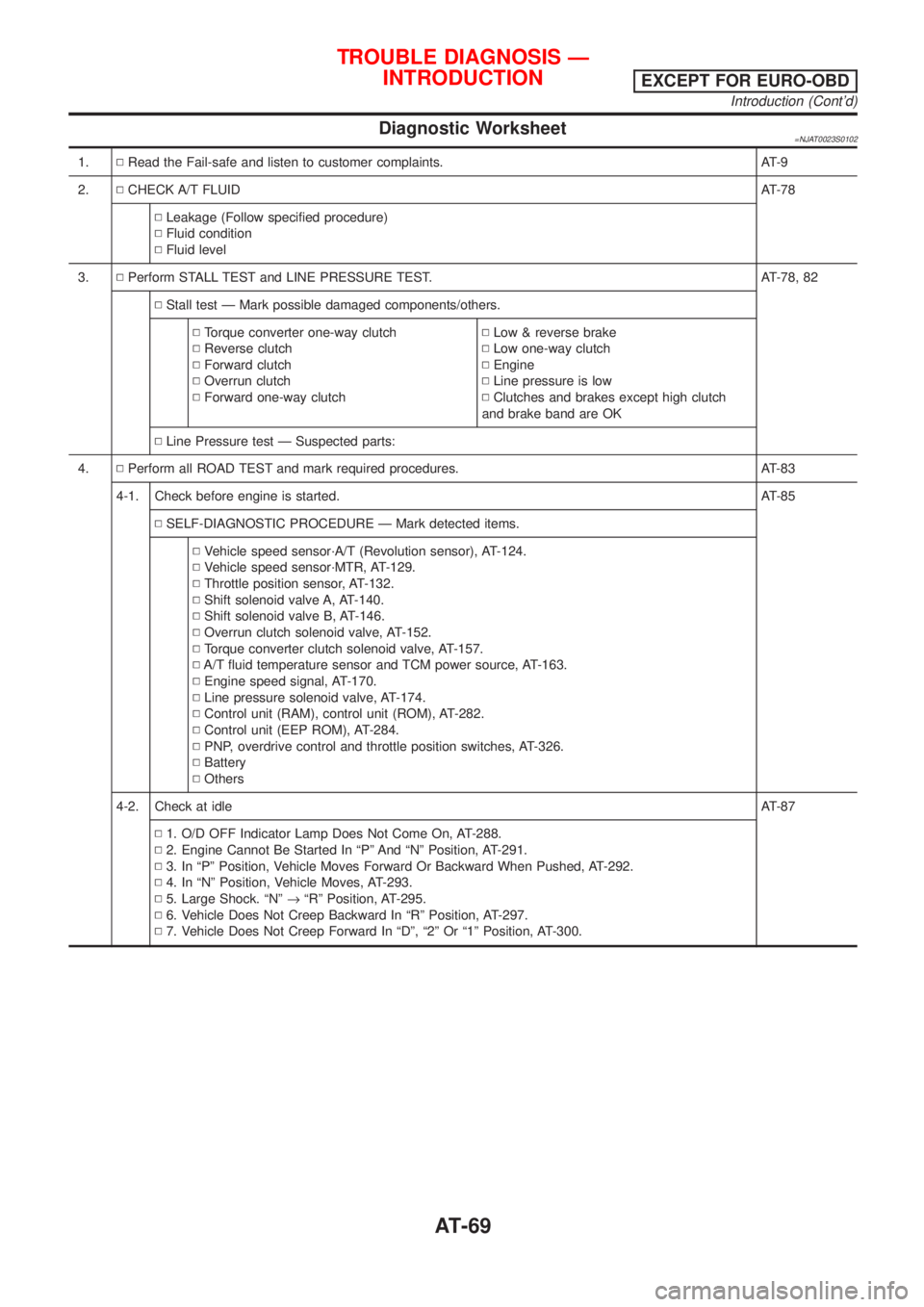
Diagnostic Worksheet=NJAT0023S0102
1.NRead the Fail-safe and listen to customer complaints. AT-9
2.NCHECK A/T FLUIDAT-78
NLeakage (Follow specified procedure)
NFluid condition
NFluid level
3.NPerform STALL TEST and LINE PRESSURE TEST. AT-78, 82
NStall test Ð Mark possible damaged components/others.
NTorque converter one-way clutch
NReverse clutch
NForward clutch
NOverrun clutch
NForward one-way clutchNLow & reverse brake
NLow one-way clutch
NEngine
NLine pressure is low
NClutches and brakes except high clutch
and brake band are OK
NLine Pressure test Ð Suspected parts:
4.NPerform all ROAD TEST and mark required procedures. AT-83
4-1. Check before engine is started. AT-85
NSELF-DIAGNOSTIC PROCEDURE Ð Mark detected items.
NVehicle speed sensor´A/T (Revolution sensor), AT-124.
NVehicle speed sensor´MTR, AT-129.
NThrottle position sensor, AT-132.
NShift solenoid valve A, AT-140.
NShift solenoid valve B, AT-146.
NOverrun clutch solenoid valve, AT-152.
NTorque converter clutch solenoid valve, AT-157.
NA/T fluid temperature sensor and TCM power source, AT-163.
NEngine speed signal, AT-170.
NLine pressure solenoid valve, AT-174.
NControl unit (RAM), control unit (ROM), AT-282.
NControl unit (EEP ROM), AT-284.
NPNP, overdrive control and throttle position switches, AT-326.
NBattery
NOthers
4-2. Check at idleAT-87
N1. O/D OFF Indicator Lamp Does Not Come On, AT-288.
N2. Engine Cannot Be Started In ªPº And ªNº Position, AT-291.
N3. In ªPº Position, Vehicle Moves Forward Or Backward When Pushed, AT-292.
N4. In ªNº Position, Vehicle Moves, AT-293.
N5. Large Shock. ªNº®ªRº Position, AT-295.
N6. Vehicle Does Not Creep Backward In ªRº Position, AT-297.
N7. Vehicle Does Not Creep Forward In ªDº, ª2º Or ª1º Position, AT-300.
TROUBLE DIAGNOSIS Ð
INTRODUCTION
EXCEPT FOR EURO-OBD
Introduction (Cont'd)
AT-69
Page 1260 of 2493
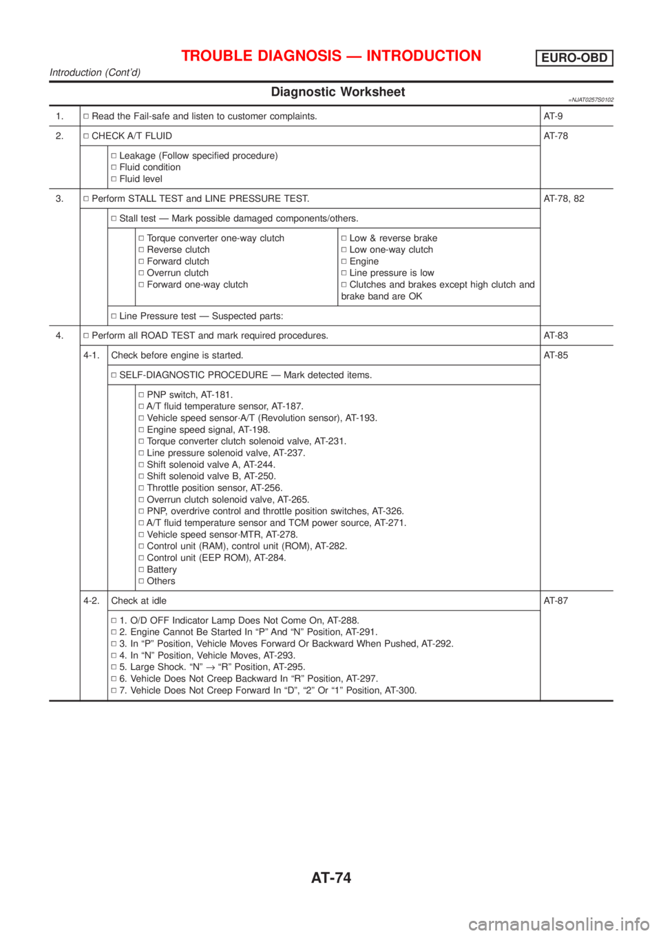
Diagnostic Worksheet=NJAT0257S0102
1.NRead the Fail-safe and listen to customer complaints. AT-9
2.NCHECK A/T FLUIDAT-78
NLeakage (Follow specified procedure)
NFluid condition
NFluid level
3.NPerform STALL TEST and LINE PRESSURE TEST. AT-78, 82
NStall test Ð Mark possible damaged components/others.
NTorque converter one-way clutch
NReverse clutch
NForward clutch
NOverrun clutch
NForward one-way clutchNLow & reverse brake
NLow one-way clutch
NEngine
NLine pressure is low
NClutches and brakes except high clutch and
brake band are OK
NLine Pressure test Ð Suspected parts:
4.NPerform all ROAD TEST and mark required procedures. AT-83
4-1. Check before engine is started. AT-85
NSELF-DIAGNOSTIC PROCEDURE Ð Mark detected items.
NPNP switch, AT-181.
NA/T fluid temperature sensor, AT-187.
NVehicle speed sensor´A/T (Revolution sensor), AT-193.
NEngine speed signal, AT-198.
NTorque converter clutch solenoid valve, AT-231.
NLine pressure solenoid valve, AT-237.
NShift solenoid valve A, AT-244.
NShift solenoid valve B, AT-250.
NThrottle position sensor, AT-256.
NOverrun clutch solenoid valve, AT-265.
NPNP, overdrive control and throttle position switches, AT-326.
NA/T fluid temperature sensor and TCM power source, AT-271.
NVehicle speed sensor´MTR, AT-278.
NControl unit (RAM), control unit (ROM), AT-282.
NControl unit (EEP ROM), AT-284.
NBattery
NOthers
4-2. Check at idleAT-87
N1. O/D OFF Indicator Lamp Does Not Come On, AT-288.
N2. Engine Cannot Be Started In ªPº And ªNº Position, AT-291.
N3. In ªPº Position, Vehicle Moves Forward Or Backward When Pushed, AT-292.
N4. In ªNº Position, Vehicle Moves, AT-293.
N5. Large Shock. ªNº®ªRº Position, AT-295.
N6. Vehicle Does Not Creep Backward In ªRº Position, AT-297.
N7. Vehicle Does Not Creep Forward In ªDº, ª2º Or ª1º Position, AT-300.
TROUBLE DIAGNOSIS Ð INTRODUCTIONEURO-OBD
Introduction (Cont'd)
AT-74
Page 1291 of 2493
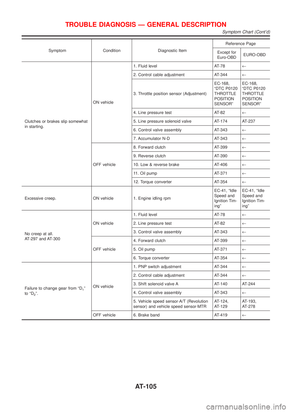
Symptom Condition Diagnostic ItemReference Page
Except for
Euro-OBDEURO-OBD
Clutches or brakes slip somewhat
in starting.ON vehicle1. Fluid level AT-78¬
2. Control cable adjustment AT-344¬
3. Throttle position sensor (Adjustment)EC-168,
ªDTC P0120
THROTTLE
POSITION
SENSORºEC-168,
ªDTC P0120
THROTTLE
POSITION
SENSORº
4. Line pressure test AT-82¬
5. Line pressure solenoid valve AT-174 AT-237
6. Control valve assembly AT-343¬
7. Accumulator N-D AT-343¬
OFF vehicle8. Forward clutch AT-399¬
9. Reverse clutch AT-390¬
10. Low & reverse brake AT-406¬
11. Oil pump AT-371¬
12. Torque converter AT-354¬
Excessive creep. ON vehicle 1. Engine idling rpmEC-41, ªIdle
Speed and
Ignition Tim-
ingºEC-41, ªIdle
Speed and
Ignition Tim-
ingº
No creep at all.
AT-297 and AT-300ON vehicle1. Fluid level AT-78¬
2. Line pressure test AT-82¬
3. Control valve assembly AT-343¬
OFF vehicle4. Forward clutch AT-399¬
5. Oil pump AT-371¬
6. Torque converter AT-354¬
Failure to change gear from ªD
1º
to ªD
2º.ON vehicle1. PNP switch adjustment AT-344¬
2. Control cable adjustment AT-344¬
3. Shift solenoid valve A AT-140 AT-244
4. Control valve assembly AT-343¬
5. Vehicle speed sensor´A/T (Revolution
sensor) and vehicle speed sensor´MTRAT-124,
AT-129AT-193,
AT-278
OFF vehicle 6. Brake band AT-419¬
TROUBLE DIAGNOSIS Ð GENERAL DESCRIPTION
Symptom Chart (Cont'd)
AT-105
Page 1637 of 2493
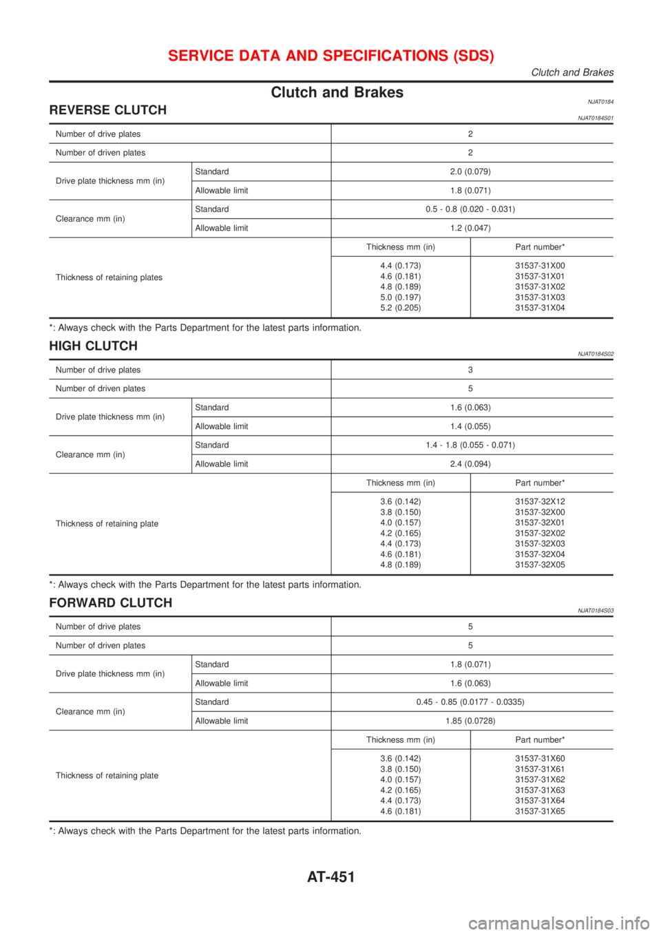
Clutch and BrakesNJAT0184REVERSE CLUTCHNJAT0184S01
Number of drive plates2
Number of driven plates2
Drive plate thickness mm (in)Standard 2.0 (0.079)
Allowable limit 1.8 (0.071)
Clearance mm (in)Standard 0.5 - 0.8 (0.020 - 0.031)
Allowable limit 1.2 (0.047)
Thickness of retaining platesThickness mm (in) Part number*
4.4 (0.173)
4.6 (0.181)
4.8 (0.189)
5.0 (0.197)
5.2 (0.205)31537-31X00
31537-31X01
31537-31X02
31537-31X03
31537-31X04
*: Always check with the Parts Department for the latest parts information.
HIGH CLUTCHNJAT0184S02
Number of drive plates3
Number of driven plates5
Drive plate thickness mm (in)Standard 1.6 (0.063)
Allowable limit 1.4 (0.055)
Clearance mm (in)Standard 1.4 - 1.8 (0.055 - 0.071)
Allowable limit 2.4 (0.094)
Thickness of retaining plateThickness mm (in) Part number*
3.6 (0.142)
3.8 (0.150)
4.0 (0.157)
4.2 (0.165)
4.4 (0.173)
4.6 (0.181)
4.8 (0.189)31537-32X12
31537-32X00
31537-32X01
31537-32X02
31537-32X03
31537-32X04
31537-32X05
*: Always check with the Parts Department for the latest parts information.
FORWARD CLUTCHNJAT0184S03
Number of drive plates5
Number of driven plates5
Drive plate thickness mm (in)Standard 1.8 (0.071)
Allowable limit 1.6 (0.063)
Clearance mm (in)Standard 0.45 - 0.85 (0.0177 - 0.0335)
Allowable limit 1.85 (0.0728)
Thickness of retaining plateThickness mm (in) Part number*
3.6 (0.142)
3.8 (0.150)
4.0 (0.157)
4.2 (0.165)
4.4 (0.173)
4.6 (0.181)31537-31X60
31537-31X61
31537-31X62
31537-31X63
31537-31X64
31537-31X65
*: Always check with the Parts Department for the latest parts information.
SERVICE DATA AND SPECIFICATIONS (SDS)
Clutch and Brakes
AT-451
Page 1638 of 2493
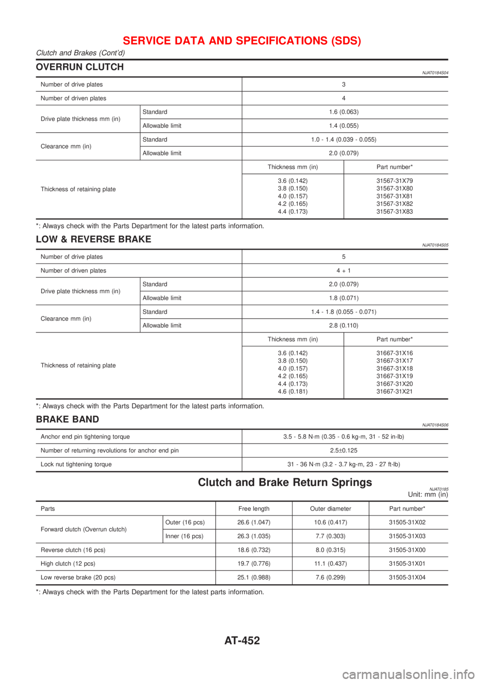
OVERRUN CLUTCHNJAT0184S04
Number of drive plates3
Number of driven plates4
Drive plate thickness mm (in)Standard 1.6 (0.063)
Allowable limit 1.4 (0.055)
Clearance mm (in)Standard 1.0 - 1.4 (0.039 - 0.055)
Allowable limit 2.0 (0.079)
Thickness of retaining plateThickness mm (in) Part number*
3.6 (0.142)
3.8 (0.150)
4.0 (0.157)
4.2 (0.165)
4.4 (0.173)31567-31X79
31567-31X80
31567-31X81
31567-31X82
31567-31X83
*: Always check with the Parts Department for the latest parts information.
LOW & REVERSE BRAKENJAT0184S05
Number of drive plates5
Number of driven plates4+1
Drive plate thickness mm (in)Standard 2.0 (0.079)
Allowable limit 1.8 (0.071)
Clearance mm (in)Standard 1.4 - 1.8 (0.055 - 0.071)
Allowable limit 2.8 (0.110)
Thickness of retaining plateThickness mm (in) Part number*
3.6 (0.142)
3.8 (0.150)
4.0 (0.157)
4.2 (0.165)
4.4 (0.173)
4.6 (0.181)31667-31X16
31667-31X17
31667-31X18
31667-31X19
31667-31X20
31667-31X21
*: Always check with the Parts Department for the latest parts information.
BRAKE BANDNJAT0184S06
Anchor end pin tightening torque 3.5 - 5.8 N´m (0.35 - 0.6 kg-m, 31 - 52 in-lb)
Number of returning revolutions for anchor end pin 2.5±0.125
Lock nut tightening torque 31 - 36 N´m (3.2 - 3.7 kg-m, 23 - 27 ft-lb)
Clutch and Brake Return SpringsNJAT0185Unit: mm (in)
Parts Free length Outer diameter Part number*
Forward clutch (Overrun clutch)Outer (16 pcs) 26.6 (1.047) 10.6 (0.417) 31505-31X02
Inner (16 pcs) 26.3 (1.035) 7.7 (0.303) 31505-31X03
Reverse clutch (16 pcs) 18.6 (0.732) 8.0 (0.315) 31505-31X00
High clutch (12 pcs) 19.7 (0.776) 11.1 (0.437) 31505-31X01
Low reverse brake (20 pcs) 25.1 (0.988) 7.6 (0.299) 31505-31X04
*: Always check with the Parts Department for the latest parts information.
SERVICE DATA AND SPECIFICATIONS (SDS)
Clutch and Brakes (Cont'd)
AT-452
Page 1647 of 2493
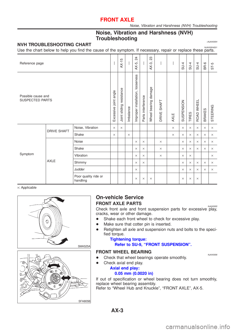
Noise, Vibration and Harshness (NVH)
Troubleshooting
=NJAX0004NVH TROUBLESHOOTING CHARTNJAX0004S01Use the chart below to help you find the cause of the symptom. If necessary, repair or replace these parts.
Reference pageÐ
AX-15
Ð
AX-5, 24
Ð
AX-3, 23
Ð
Ð
SU-4
SU-4
SU-4
BR-6
ST-5
Possible cause and
SUSPECTED PARTS
Excessive joint angle
Joint sliding resistance
Imbalance
Improper installation, looseness
Parts interference
Wheel bearing damage
DRIVE SHAFT
AXLE
SUSPENSION
TIRES
ROAD WHEEL
BRAKES
STEERING
SymptomDRIVE SHAFTNoise, Vibration´´ ´ ´´´´´
Shake´ ´ ´ ´´´´´
AXLENoise´´ ´ ´´´´´
Shake´´ ´ ´´´´´
Vibration´´ ´ ´´ ´
Shimmy´´ ´´´´´
Judder´ ´´´´´
Poor quality ride or
handling´´´ ´´´
´: Applicable
SMA525A
On-vehicle Service
FRONT AXLE PARTSNJAX0005Check front axle and front suspension parts for excessive play,
cracks, wear or other damage.
+Shake each front wheel to check for excessive play.
+Make sure that cotter pin is inserted.
+Retighten all axle and suspension nuts and bolts to the speci-
fied torque.
Tightening torque:
Refer to SU-9, ªFRONT SUSPENSIONº.
SFA805B
FRONT WHEEL BEARINGNJAX0006+Check that wheel bearings operate smoothly.
+Check axial end play.
Axial end play:
0.05 mm (0.0020 in)
If out of specification or wheel bearing does not turn smoothly,
replace wheel bearing assembly.
Refer to ªWheel Hub and Knuckleº, ªFRONT AXLEº, AX-5.
FRONT AXLE
Noise, Vibration and Harshness (NVH) Troubleshooting
AX-3
Page 1669 of 2493
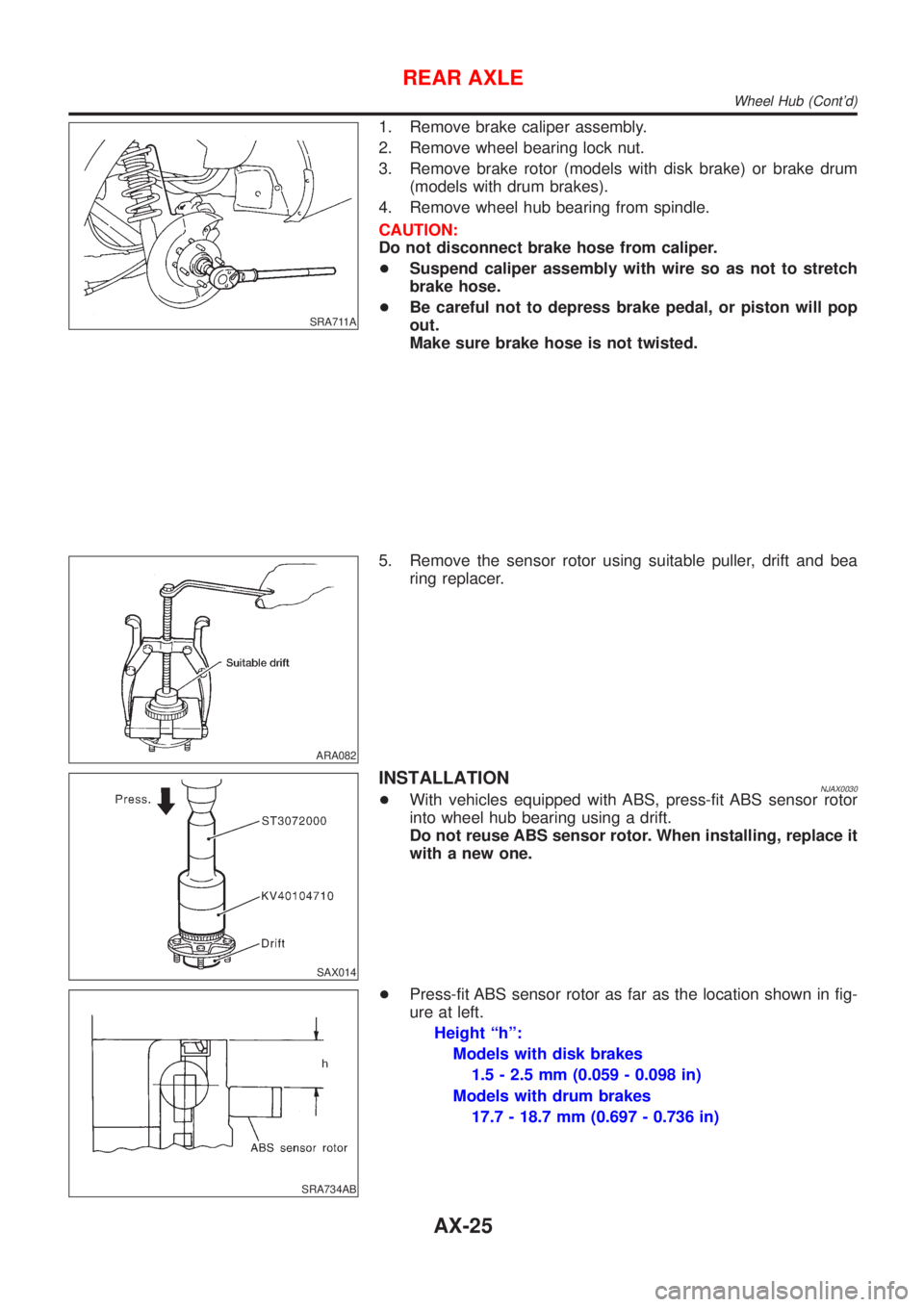
SRA711A
1. Remove brake caliper assembly.
2. Remove wheel bearing lock nut.
3. Remove brake rotor (models with disk brake) or brake drum
(models with drum brakes).
4. Remove wheel hub bearing from spindle.
CAUTION:
Do not disconnect brake hose from caliper.
+Suspend caliper assembly with wire so as not to stretch
brake hose.
+Be careful not to depress brake pedal, or piston will pop
out.
Make sure brake hose is not twisted.
ARA082
5. Remove the sensor rotor using suitable puller, drift and bea
ring replacer.
SAX014
INSTALLATIONNJAX0030+With vehicles equipped with ABS, press-fit ABS sensor rotor
into wheel hub bearing using a drift.
Do not reuse ABS sensor rotor. When installing, replace it
with a new one.
SRA734AB
+Press-fit ABS sensor rotor as far as the location shown in fig-
ure at left.
Height ªhº:
Models with disk brakes
1.5 - 2.5 mm (0.059 - 0.098 in)
Models with drum brakes
17.7 - 18.7 mm (0.697 - 0.736 in)
REAR AXLE
Wheel Hub (Cont'd)
AX-25