iac NISSAN ALMERA N16 2001 Electronic Repair Manual
[x] Cancel search | Manufacturer: NISSAN, Model Year: 2001, Model line: ALMERA N16, Model: NISSAN ALMERA N16 2001Pages: 2493, PDF Size: 66.97 MB
Page 53 of 2493
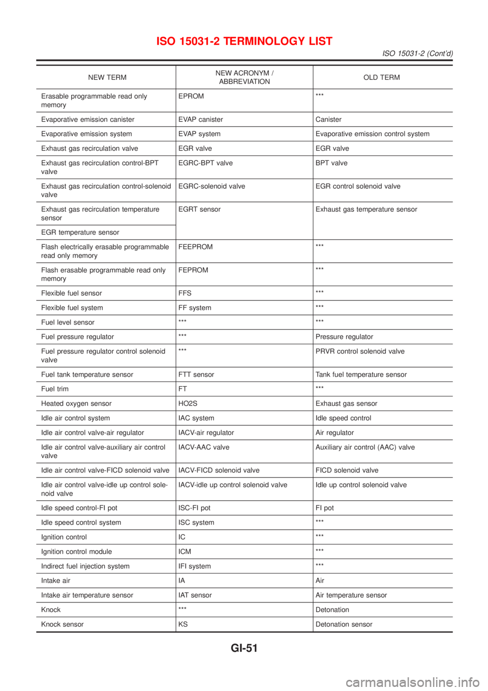
NEW TERMNEW ACRONYM /
ABBREVIATIONOLD TERM
Erasable programmable read only
memoryEPROM ***
Evaporative emission canister EVAP canister Canister
Evaporative emission system EVAP system Evaporative emission control system
Exhaust gas recirculation valve EGR valve EGR valve
Exhaust gas recirculation control-BPT
valveEGRC-BPT valve BPT valve
Exhaust gas recirculation control-solenoid
valveEGRC-solenoid valve EGR control solenoid valve
Exhaust gas recirculation temperature
sensorEGRT sensor Exhaust gas temperature sensor
EGR temperature sensor
Flash electrically erasable programmable
read only memoryFEEPROM ***
Flash erasable programmable read only
memoryFEPROM ***
Flexible fuel sensor FFS ***
Flexible fuel system FF system ***
Fuel level sensor *** ***
Fuel pressure regulator *** Pressure regulator
Fuel pressure regulator control solenoid
valve*** PRVR control solenoid valve
Fuel tank temperature sensor FTT sensor Tank fuel temperature sensor
Fuel trim FT ***
Heated oxygen sensor HO2S Exhaust gas sensor
Idle air control system IAC system Idle speed control
Idle air control valve-air regulator IACV-air regulator Air regulator
Idle air control valve-auxiliary air control
valveIACV-AAC valve Auxiliary air control (AAC) valve
Idle air control valve-FICD solenoid valve IACV-FICD solenoid valve FICD solenoid valve
Idle air control valve-idle up control sole-
noid valveIACV-idle up control solenoid valve Idle up control solenoid valve
Idle speed control-FI pot ISC-FI pot FI pot
Idle speed control system ISC system ***
Ignition control IC ***
Ignition control module ICM ***
Indirect fuel injection system IFI system ***
Intake air IA Air
Intake air temperature sensor IAT sensor Air temperature sensor
Knock *** Detonation
Knock sensor KS Detonation sensor
ISO 15031-2 TERMINOLOGY LIST
ISO 15031-2 (Cont'd)
GI-51
Page 90 of 2493
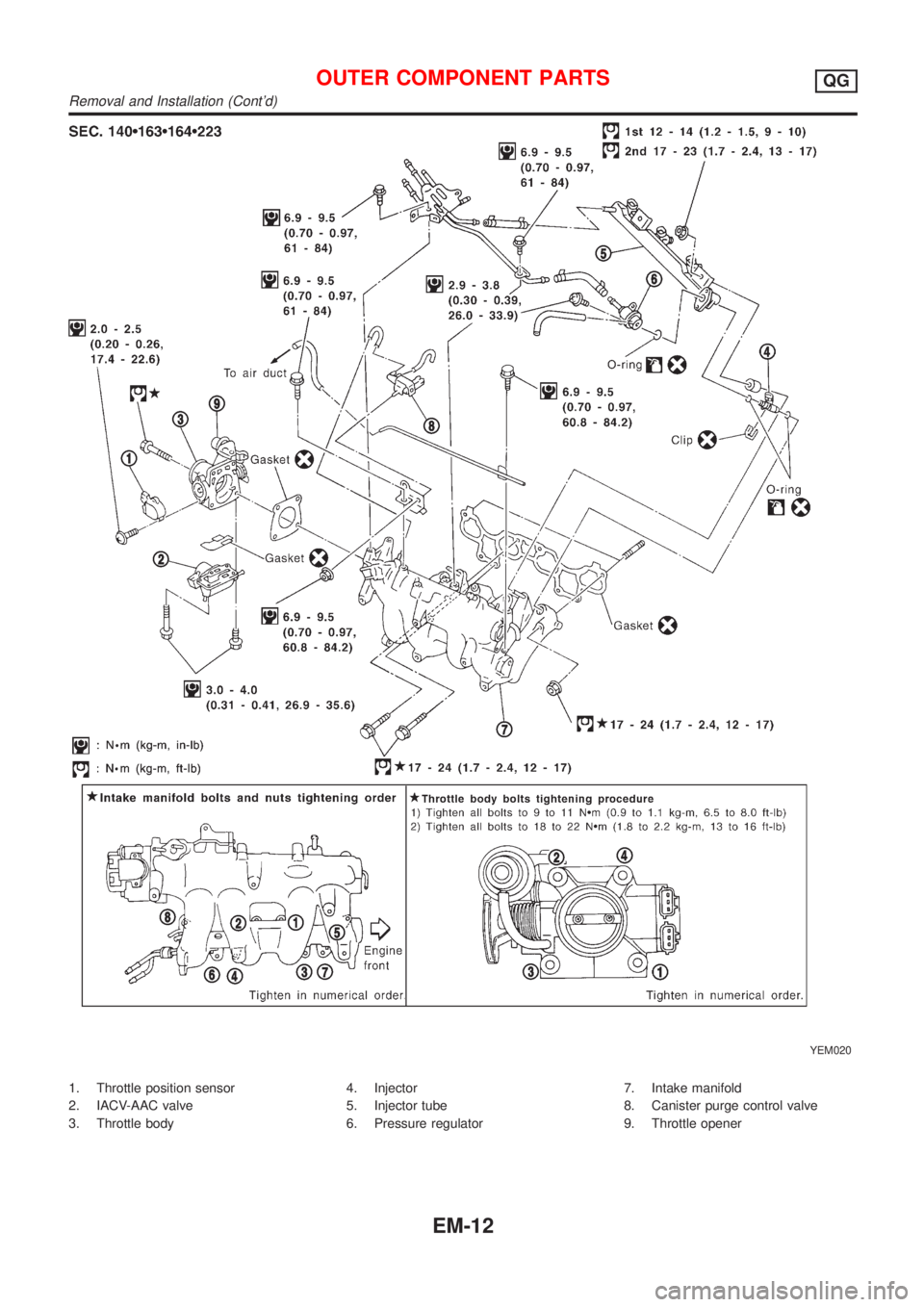
YEM020
1. Throttle position sensor
2. IACV-AAC valve
3. Throttle body4. Injector
5. Injector tube
6. Pressure regulator7. Intake manifold
8. Canister purge control valve
9. Throttle opener
OUTER COMPONENT PARTSQG
Removal and Installation (Cont'd)
EM-12
Page 300 of 2493
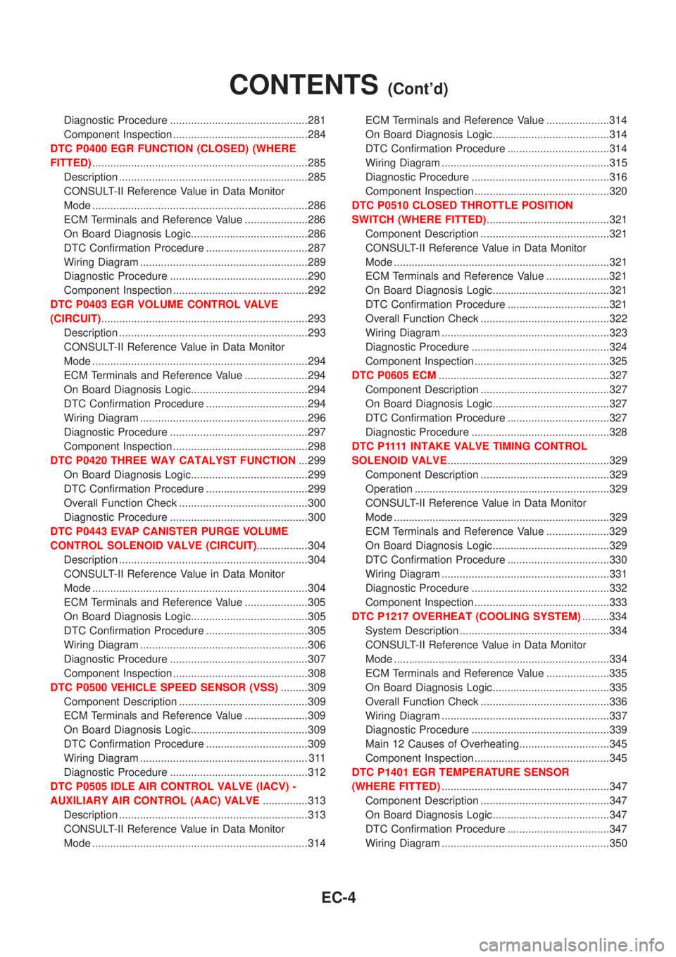
Diagnostic Procedure ..............................................281
Component Inspection .............................................284
DTC P0400 EGR FUNCTION (CLOSED) (WHERE
FITTED)........................................................................285
Description ...............................................................285
CONSULT-II Reference Value in Data Monitor
Mode ........................................................................286
ECM Terminals and Reference Value .....................286
On Board Diagnosis Logic.......................................286
DTC Confirmation Procedure ..................................287
Wiring Diagram ........................................................289
Diagnostic Procedure ..............................................290
Component Inspection .............................................292
DTC P0403 EGR VOLUME CONTROL VALVE
(CIRCUIT).....................................................................293
Description ...............................................................293
CONSULT-II Reference Value in Data Monitor
Mode ........................................................................294
ECM Terminals and Reference Value .....................294
On Board Diagnosis Logic.......................................294
DTC Confirmation Procedure ..................................294
Wiring Diagram ........................................................296
Diagnostic Procedure ..............................................297
Component Inspection .............................................298
DTC P0420 THREE WAY CATALYST FUNCTION...299
On Board Diagnosis Logic.......................................299
DTC Confirmation Procedure ..................................299
Overall Function Check ...........................................300
Diagnostic Procedure ..............................................300
DTC P0443 EVAP CANISTER PURGE VOLUME
CONTROL SOLENOID VALVE (CIRCUIT).................304
Description ...............................................................304
CONSULT-II Reference Value in Data Monitor
Mode ........................................................................304
ECM Terminals and Reference Value .....................305
On Board Diagnosis Logic.......................................305
DTC Confirmation Procedure ..................................305
Wiring Diagram ........................................................306
Diagnostic Procedure ..............................................307
Component Inspection .............................................308
DTC P0500 VEHICLE SPEED SENSOR (VSS).........309
Component Description ...........................................309
ECM Terminals and Reference Value .....................309
On Board Diagnosis Logic.......................................309
DTC Confirmation Procedure ..................................309
Wiring Diagram ........................................................ 311
Diagnostic Procedure ..............................................312
DTC P0505 IDLE AIR CONTROL VALVE (IACV) -
AUXILIARY AIR CONTROL (AAC) VALVE...............313
Description ...............................................................313
CONSULT-II Reference Value in Data Monitor
Mode ........................................................................314ECM Terminals and Reference Value .....................314
On Board Diagnosis Logic.......................................314
DTC Confirmation Procedure ..................................314
Wiring Diagram ........................................................315
Diagnostic Procedure ..............................................316
Component Inspection .............................................320
DTC P0510 CLOSED THROTTLE POSITION
SWITCH (WHERE FITTED).........................................321
Component Description ...........................................321
CONSULT-II Reference Value in Data Monitor
Mode ........................................................................321
ECM Terminals and Reference Value .....................321
On Board Diagnosis Logic.......................................321
DTC Confirmation Procedure ..................................321
Overall Function Check ...........................................322
Wiring Diagram ........................................................323
Diagnostic Procedure ..............................................324
Component Inspection .............................................325
DTC P0605 ECM.........................................................327
Component Description ...........................................327
On Board Diagnosis Logic.......................................327
DTC Confirmation Procedure ..................................327
Diagnostic Procedure ..............................................328
D T C P 1111INTAKE VALVE TIMING CONTROL
SOLENOID VALVE......................................................329
Component Description ...........................................329
Operation .................................................................329
CONSULT-II Reference Value in Data Monitor
Mode ........................................................................329
ECM Terminals and Reference Value .....................329
On Board Diagnosis Logic.......................................329
DTC Confirmation Procedure ..................................330
Wiring Diagram ........................................................331
Diagnostic Procedure ..............................................332
Component Inspection .............................................333
DTC P1217 OVERHEAT (COOLING SYSTEM).........334
System Description ..................................................334
CONSULT-II Reference Value in Data Monitor
Mode ........................................................................334
ECM Terminals and Reference Value .....................335
On Board Diagnosis Logic.......................................335
Overall Function Check ...........................................336
Wiring Diagram ........................................................337
Diagnostic Procedure ..............................................339
Main 12 Causes of Overheating..............................345
Component Inspection .............................................345
DTC P1401 EGR TEMPERATURE SENSOR
(WHERE FITTED)........................................................347
Component Description ...........................................347
On Board Diagnosis Logic.......................................347
DTC Confirmation Procedure ..................................347
Wiring Diagram ........................................................350
CONTENTS(Cont'd)
EC-4
Page 301 of 2493
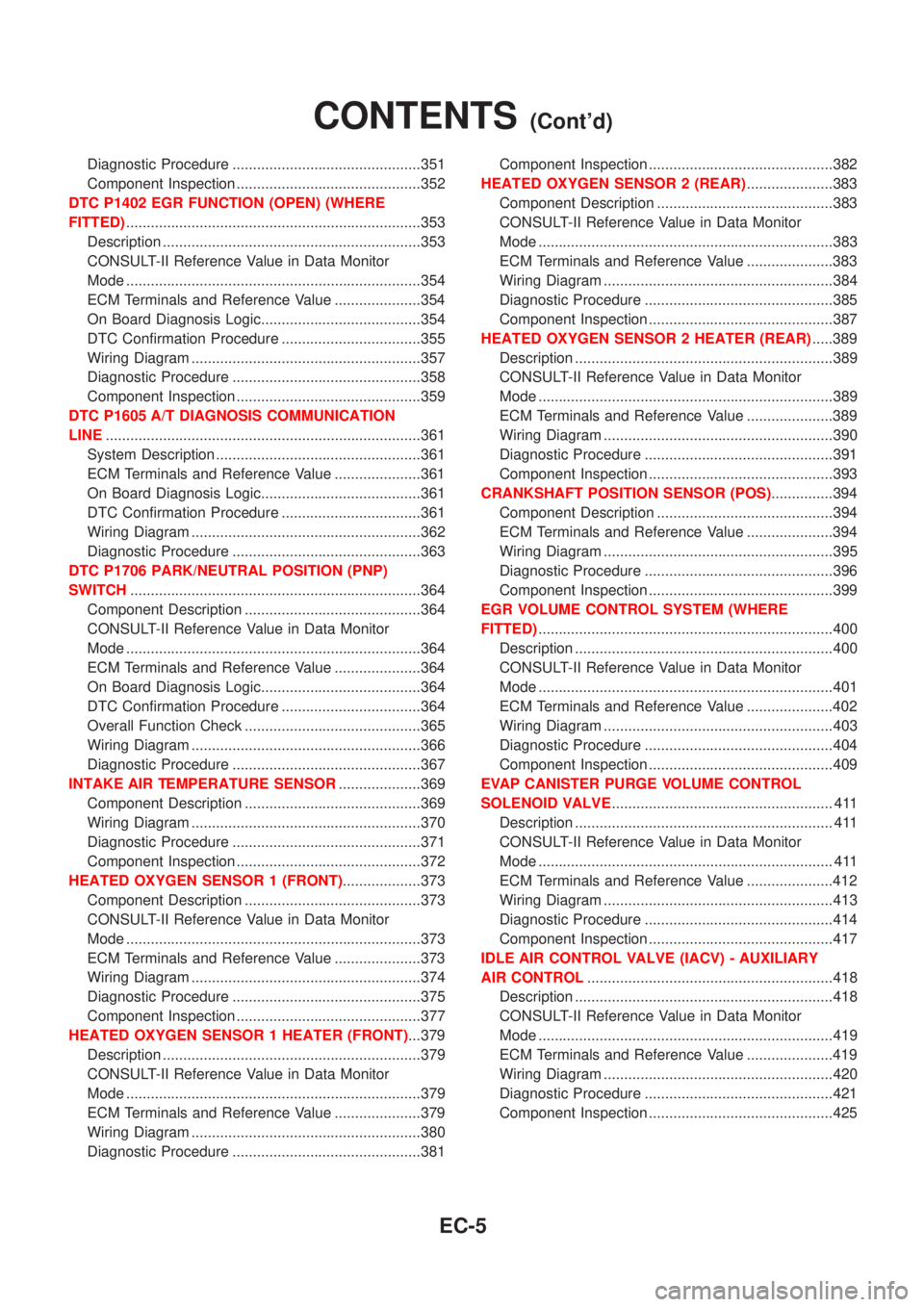
Diagnostic Procedure ..............................................351
Component Inspection .............................................352
DTC P1402 EGR FUNCTION (OPEN) (WHERE
FITTED)........................................................................353
Description ...............................................................353
CONSULT-II Reference Value in Data Monitor
Mode ........................................................................354
ECM Terminals and Reference Value .....................354
On Board Diagnosis Logic.......................................354
DTC Confirmation Procedure ..................................355
Wiring Diagram ........................................................357
Diagnostic Procedure ..............................................358
Component Inspection .............................................359
DTC P1605 A/T DIAGNOSIS COMMUNICATION
LINE.............................................................................361
System Description ..................................................361
ECM Terminals and Reference Value .....................361
On Board Diagnosis Logic.......................................361
DTC Confirmation Procedure ..................................361
Wiring Diagram ........................................................362
Diagnostic Procedure ..............................................363
DTC P1706 PARK/NEUTRAL POSITION (PNP)
SWITCH.......................................................................364
Component Description ...........................................364
CONSULT-II Reference Value in Data Monitor
Mode ........................................................................364
ECM Terminals and Reference Value .....................364
On Board Diagnosis Logic.......................................364
DTC Confirmation Procedure ..................................364
Overall Function Check ...........................................365
Wiring Diagram ........................................................366
Diagnostic Procedure ..............................................367
INTAKE AIR TEMPERATURE SENSOR....................369
Component Description ...........................................369
Wiring Diagram ........................................................370
Diagnostic Procedure ..............................................371
Component Inspection .............................................372
HEATED OXYGEN SENSOR 1 (FRONT)...................373
Component Description ...........................................373
CONSULT-II Reference Value in Data Monitor
Mode ........................................................................373
ECM Terminals and Reference Value .....................373
Wiring Diagram ........................................................374
Diagnostic Procedure ..............................................375
Component Inspection .............................................377
HEATED OXYGEN SENSOR 1 HEATER (FRONT)...379
Description ...............................................................379
CONSULT-II Reference Value in Data Monitor
Mode ........................................................................379
ECM Terminals and Reference Value .....................379
Wiring Diagram ........................................................380
Diagnostic Procedure ..............................................381Component Inspection .............................................382
HEATED OXYGEN SENSOR 2 (REAR).....................383
Component Description ...........................................383
CONSULT-II Reference Value in Data Monitor
Mode ........................................................................383
ECM Terminals and Reference Value .....................383
Wiring Diagram ........................................................384
Diagnostic Procedure ..............................................385
Component Inspection .............................................387
HEATED OXYGEN SENSOR 2 HEATER (REAR).....389
Description ...............................................................389
CONSULT-II Reference Value in Data Monitor
Mode ........................................................................389
ECM Terminals and Reference Value .....................389
Wiring Diagram ........................................................390
Diagnostic Procedure ..............................................391
Component Inspection .............................................393
CRANKSHAFT POSITION SENSOR (POS)...............394
Component Description ...........................................394
ECM Terminals and Reference Value .....................394
Wiring Diagram ........................................................395
Diagnostic Procedure ..............................................396
Component Inspection .............................................399
EGR VOLUME CONTROL SYSTEM (WHERE
FITTED)........................................................................400
Description ...............................................................400
CONSULT-II Reference Value in Data Monitor
Mode ........................................................................401
ECM Terminals and Reference Value .....................402
Wiring Diagram ........................................................403
Diagnostic Procedure ..............................................404
Component Inspection .............................................409
EVAP CANISTER PURGE VOLUME CONTROL
SOLENOID VALVE...................................................... 411
Description ............................................................... 411
CONSULT-II Reference Value in Data Monitor
Mode ........................................................................ 411
ECM Terminals and Reference Value .....................412
Wiring Diagram ........................................................413
Diagnostic Procedure ..............................................414
Component Inspection .............................................417
IDLE AIR CONTROL VALVE (IACV) - AUXILIARY
AIR CONTROL............................................................418
Description ...............................................................418
CONSULT-II Reference Value in Data Monitor
Mode ........................................................................419
ECM Terminals and Reference Value .....................419
Wiring Diagram ........................................................420
Diagnostic Procedure ..............................................421
Component Inspection .............................................425
CONTENTS(Cont'd)
EC-5
Page 302 of 2493
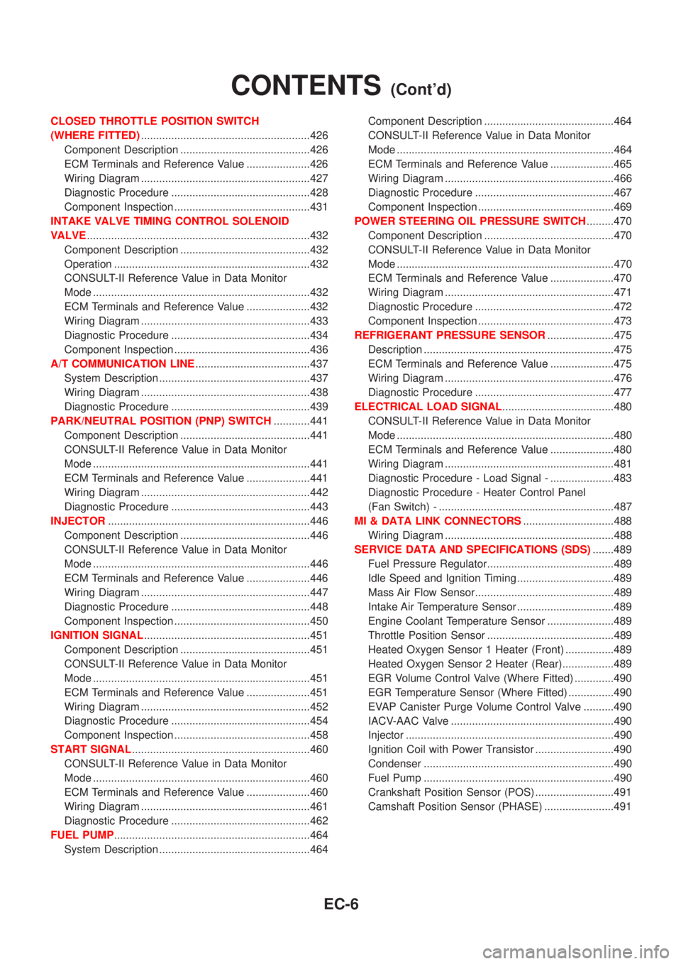
CLOSED THROTTLE POSITION SWITCH
(WHERE FITTED)........................................................426
Component Description ...........................................426
ECM Terminals and Reference Value .....................426
Wiring Diagram ........................................................427
Diagnostic Procedure ..............................................428
Component Inspection .............................................431
INTAKE VALVE TIMING CONTROL SOLENOID
VALVE..........................................................................432
Component Description ...........................................432
Operation .................................................................432
CONSULT-II Reference Value in Data Monitor
Mode ........................................................................432
ECM Terminals and Reference Value .....................432
Wiring Diagram ........................................................433
Diagnostic Procedure ..............................................434
Component Inspection .............................................436
A/T COMMUNICATION LINE......................................437
System Description ..................................................437
Wiring Diagram ........................................................438
Diagnostic Procedure ..............................................439
PARK/NEUTRAL POSITION (PNP) SWITCH............441
Component Description ...........................................441
CONSULT-II Reference Value in Data Monitor
Mode ........................................................................441
ECM Terminals and Reference Value .....................441
Wiring Diagram ........................................................442
Diagnostic Procedure ..............................................443
INJECTOR...................................................................446
Component Description ...........................................446
CONSULT-II Reference Value in Data Monitor
Mode ........................................................................446
ECM Terminals and Reference Value .....................446
Wiring Diagram ........................................................447
Diagnostic Procedure ..............................................448
Component Inspection .............................................450
IGNITION SIGNAL.......................................................451
Component Description ...........................................451
CONSULT-II Reference Value in Data Monitor
Mode ........................................................................451
ECM Terminals and Reference Value .....................451
Wiring Diagram ........................................................452
Diagnostic Procedure ..............................................454
Component Inspection .............................................458
START SIGNAL...........................................................460
CONSULT-II Reference Value in Data Monitor
Mode ........................................................................460
ECM Terminals and Reference Value .....................460
Wiring Diagram ........................................................461
Diagnostic Procedure ..............................................462
FUEL PUMP.................................................................464
System Description ..................................................464Component Description ...........................................464
CONSULT-II Reference Value in Data Monitor
Mode ........................................................................464
ECM Terminals and Reference Value .....................465
Wiring Diagram ........................................................466
Diagnostic Procedure ..............................................467
Component Inspection .............................................469
POWER STEERING OIL PRESSURE SWITCH.........470
Component Description ...........................................470
CONSULT-II Reference Value in Data Monitor
Mode ........................................................................470
ECM Terminals and Reference Value .....................470
Wiring Diagram ........................................................471
Diagnostic Procedure ..............................................472
Component Inspection .............................................473
REFRIGERANT PRESSURE SENSOR......................475
Description ...............................................................475
ECM Terminals and Reference Value .....................475
Wiring Diagram ........................................................476
Diagnostic Procedure ..............................................477
ELECTRICAL LOAD SIGNAL.....................................480
CONSULT-II Reference Value in Data Monitor
Mode ........................................................................480
ECM Terminals and Reference Value .....................480
Wiring Diagram ........................................................481
Diagnostic Procedure - Load Signal - .....................483
Diagnostic Procedure - Heater Control Panel
(Fan Switch) - ..........................................................487
MI & DATA LINK CONNECTORS..............................488
Wiring Diagram ........................................................488
SERVICE DATA AND SPECIFICATIONS (SDS).......489
Fuel Pressure Regulator..........................................489
Idle Speed and Ignition Timing ................................489
Mass Air Flow Sensor..............................................489
Intake Air Temperature Sensor ................................489
Engine Coolant Temperature Sensor ......................489
Throttle Position Sensor ..........................................489
Heated Oxygen Sensor 1 Heater (Front) ................489
Heated Oxygen Sensor 2 Heater (Rear).................489
EGR Volume Control Valve (Where Fitted) .............490
EGR Temperature Sensor (Where Fitted) ...............490
EVAP Canister Purge Volume Control Valve ..........490
IACV-AAC Valve ......................................................490
Injector .....................................................................490
Ignition Coil with Power Transistor ..........................490
Condenser ...............................................................490
Fuel Pump ...............................................................490
Crankshaft Position Sensor (POS) ..........................491
Camshaft Position Sensor (PHASE) .......................491
CONTENTS(Cont'd)
EC-6
Page 307 of 2493
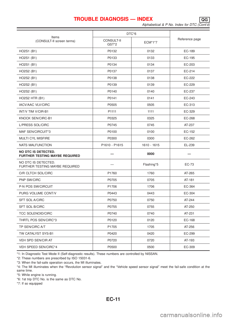
Items
(CONSULT-II screen terms)DTC*6
Reference page
CONSULT-II
GST*2ECM*1*7
HO2S1 (B1) P0132 0132 EC-189
HO2S1 (B1) P0133 0133 EC-195
HO2S1 (B1) P0134 0134 EC-203
HO2S2 (B1) P0137 0137 EC-214
HO2S2 (B1) P0138 0138 EC-222
HO2S2 (B1) P0139 0139 EC-229
HO2S2 (B1) P0140 0140 EC-237
HO2S2 HTR (B1) P0141 0141 EC-243
IACV/AAC VLV/CIRC P0505 0505 EC-313
INT/V TIM V/CIR-B1 P1111 1111EC-329
KNOCK SEN/CIRC-B1 P0325 0325 EC-268
L/PRESS SOL/CIRC P0745 0745 AT-237
MAF SEN/CIRCUIT*3 P0100 0100 EC-152
MULTI CYL MISFIRE P0300 0300 EC-262
NATS MALFUNCTION P1610 - P1615 1610 - 1615 EL-239
NO DTC IS DETECTED.
FURTHER TESTING MAYBE REQUIREDÐ 0000 Ð
NO DTC IS DETECTED.
FURTHER TESTING MAYBE REQUIREDÐ Flashing*5 EC-73
O/R CLTCH SOL/CIRC P1760 1760 AT-265
PNP SW/CIRC P0705 0705 AT-181
P-N POS SW/CIRCUIT P1706 1706 EC-364
PURG VOLUME CONT/V P0443 0443 EC-304
SFT SOL A/CIRC P0750 0750 AT-244
SFT SOL B/CIRC P0755 0755 AT-250
TCC SOLENOID/CIRC P0740 0740 AT-231
THRTL POS SEN/CIRC*3 P0120 0120 EC-168
TP SEN/CIRC A/T P1705 1705 AT-256
TW CATALYST SYS-B1 P0420 0420 EC-299
VEH SPD SEN/CIR AT P0720 0720 AT-193
VEH SPEED SEN/CIRC*4 P0500 0500 EC-309
*1: In Diagnostic Test Mode II (Self-diagnostic results). These numbers are controlled by NISSAN.
*2: These numbers are prescribed by ISO 15031-6.
*3: When the fail-safe operation occurs, the MI illuminates.
*4: The MI illuminates when the ªRevolution sensor signalº and the ªVehicle speed sensor signalº meet the fail-safe condition at the
same time.
*5: While engine is running.
*6: 1st trip DTC No. is the same as DTC No.
*7: If so equipped
TROUBLE DIAGNOSIS Ð INDEXQG
Alphabetical & P No. Index for DTC (Cont'd)
EC-11
Page 308 of 2493
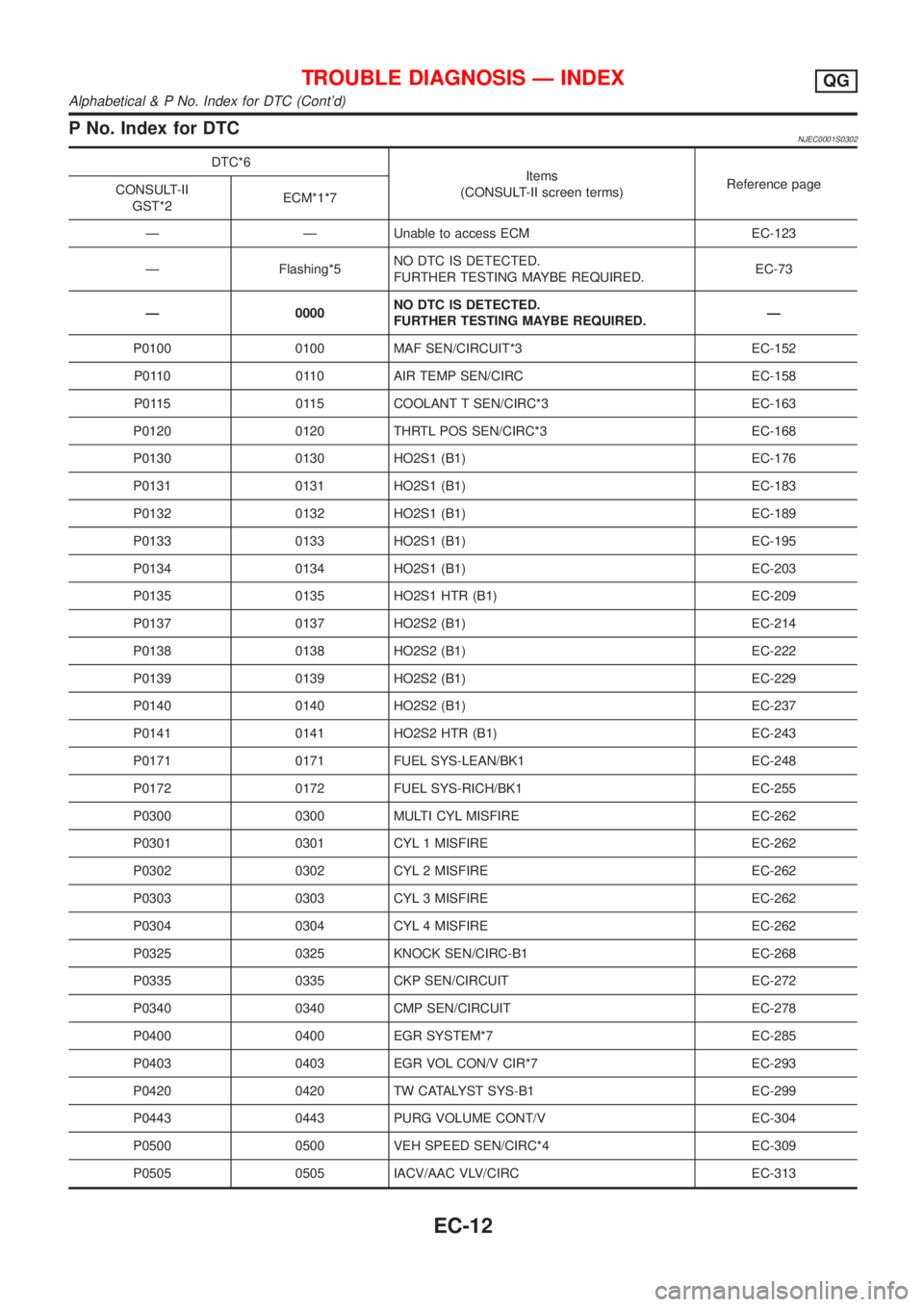
P No. Index for DTCNJEC0001S0302
DTC*6
Items
(CONSULT-II screen terms)Reference page
CONSULT-II
GST*2ECM*1*7
Ð Ð Unable to access ECM EC-123
Ð Flashing*5NO DTC IS DETECTED.
FURTHER TESTING MAYBE REQUIRED.EC-73
Ð 0000NO DTC IS DETECTED.
FURTHER TESTING MAYBE REQUIRED.Ð
P0100 0100 MAF SEN/CIRCUIT*3 EC-152
P0110 0110 AIR TEMP SEN/CIRC EC-158
P0115 0115 COOLANT T SEN/CIRC*3 EC-163
P0120 0120 THRTL POS SEN/CIRC*3 EC-168
P0130 0130 HO2S1 (B1) EC-176
P0131 0131 HO2S1 (B1) EC-183
P0132 0132 HO2S1 (B1) EC-189
P0133 0133 HO2S1 (B1) EC-195
P0134 0134 HO2S1 (B1) EC-203
P0135 0135 HO2S1 HTR (B1) EC-209
P0137 0137 HO2S2 (B1) EC-214
P0138 0138 HO2S2 (B1) EC-222
P0139 0139 HO2S2 (B1) EC-229
P0140 0140 HO2S2 (B1) EC-237
P0141 0141 HO2S2 HTR (B1) EC-243
P0171 0171 FUEL SYS-LEAN/BK1 EC-248
P0172 0172 FUEL SYS-RICH/BK1 EC-255
P0300 0300 MULTI CYL MISFIRE EC-262
P0301 0301 CYL 1 MISFIRE EC-262
P0302 0302 CYL 2 MISFIRE EC-262
P0303 0303 CYL 3 MISFIRE EC-262
P0304 0304 CYL 4 MISFIRE EC-262
P0325 0325 KNOCK SEN/CIRC-B1 EC-268
P0335 0335 CKP SEN/CIRCUIT EC-272
P0340 0340 CMP SEN/CIRCUIT EC-278
P0400 0400 EGR SYSTEM*7 EC-285
P0403 0403 EGR VOL CON/V CIR*7 EC-293
P0420 0420 TW CATALYST SYS-B1 EC-299
P0443 0443 PURG VOLUME CONT/V EC-304
P0500 0500 VEH SPEED SEN/CIRC*4 EC-309
P0505 0505 IACV/AAC VLV/CIRC EC-313
TROUBLE DIAGNOSIS Ð INDEXQG
Alphabetical & P No. Index for DTC (Cont'd)
EC-12
Page 314 of 2493
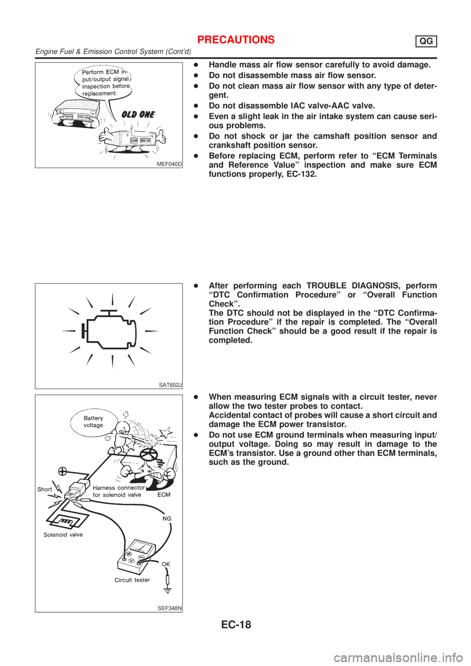
MEF040D
+Handle mass air flow sensor carefully to avoid damage.
+Do not disassemble mass air flow sensor.
+Do not clean mass air flow sensor with any type of deter-
gent.
+Do not disassemble IAC valve-AAC valve.
+Even a slight leak in the air intake system can cause seri-
ous problems.
+Do not shock or jar the camshaft position sensor and
crankshaft position sensor.
+Before replacing ECM, perform refer to ªECM Terminals
and Reference Valueº inspection and make sure ECM
functions properly, EC-132.
SAT652J
+After performing each TROUBLE DIAGNOSIS, perform
ªDTC Confirmation Procedureº or ªOverall Function
Checkº.
The DTC should not be displayed in the ªDTC Confirma-
tion Procedureº if the repair is completed. The ªOverall
Function Checkº should be a good result if the repair is
completed.
SEF348N
+When measuring ECM signals with a circuit tester, never
allow the two tester probes to contact.
Accidental contact of probes will cause a short circuit and
damage the ECM power transistor.
+Do not use ECM ground terminals when measuring input/
output voltage. Doing so may result in damage to the
ECM's transistor. Use a ground other than ECM terminals,
such as the ground.
PRECAUTIONSQG
Engine Fuel & Emission Control System (Cont'd)
EC-18
Page 324 of 2493
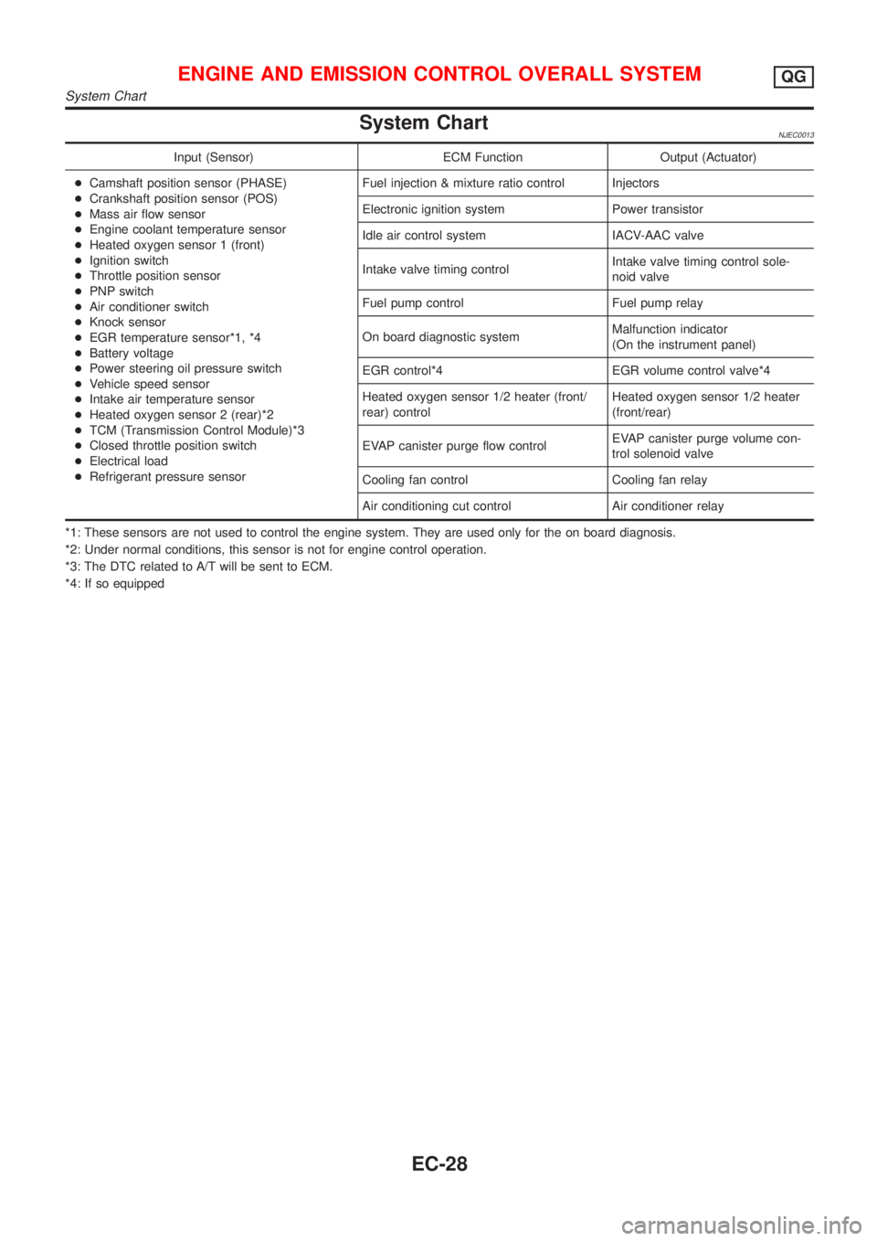
System ChartNJEC0013
Input (Sensor) ECM Function Output (Actuator)
+Camshaft position sensor (PHASE)
+Crankshaft position sensor (POS)
+Mass air flow sensor
+Engine coolant temperature sensor
+Heated oxygen sensor 1 (front)
+Ignition switch
+Throttle position sensor
+PNP switch
+Air conditioner switch
+Knock sensor
+EGR temperature sensor*1, *4
+Battery voltage
+Power steering oil pressure switch
+Vehicle speed sensor
+Intake air temperature sensor
+Heated oxygen sensor 2 (rear)*2
+TCM (Transmission Control Module)*3
+Closed throttle position switch
+Electrical load
+Refrigerant pressure sensorFuel injection & mixture ratio control Injectors
Electronic ignition system Power transistor
Idle air control system IACV-AAC valve
Intake valve timing controlIntake valve timing control sole-
noid valve
Fuel pump control Fuel pump relay
On board diagnostic systemMalfunction indicator
(On the instrument panel)
EGR control*4 EGR volume control valve*4
Heated oxygen sensor 1/2 heater (front/
rear) controlHeated oxygen sensor 1/2 heater
(front/rear)
EVAP canister purge flow controlEVAP canister purge volume con-
trol solenoid valve
Cooling fan control Cooling fan relay
Air conditioning cut control Air conditioner relay
*1: These sensors are not used to control the engine system. They are used only for the on board diagnosis.
*2: Under normal conditions, this sensor is not for engine control operation.
*3: The DTC related to A/T will be sent to ECM.
*4: If so equipped
ENGINE AND EMISSION CONTROL OVERALL SYSTEMQG
System Chart
EC-28
Page 339 of 2493
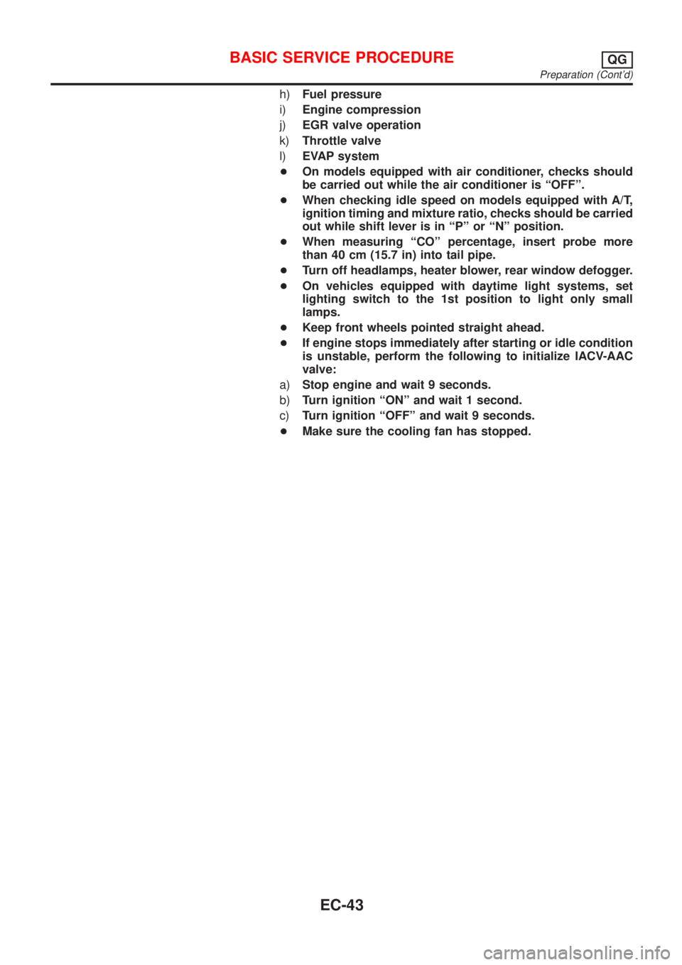
h)Fuel pressure
i)Engine compression
j)EGR valve operation
k)Throttle valve
l)EVAP system
+On models equipped with air conditioner, checks should
be carried out while the air conditioner is ªOFFº.
+When checking idle speed on models equipped with A/T,
ignition timing and mixture ratio, checks should be carried
out while shift lever is in ªPº or ªNº position.
+When measuring ªCOº percentage, insert probe more
than 40 cm (15.7 in) into tail pipe.
+Turn off headlamps, heater blower, rear window defogger.
+On vehicles equipped with daytime light systems, set
lighting switch to the 1st position to light only small
lamps.
+Keep front wheels pointed straight ahead.
+If engine stops immediately after starting or idle condition
is unstable, perform the following to initialize IACV-AAC
valve:
a)Stop engine and wait 9 seconds.
b)Turn ignition ªONº and wait 1 second.
c)Turn ignition ªOFFº and wait 9 seconds.
+Make sure the cooling fan has stopped.
BASIC SERVICE PROCEDUREQG
Preparation (Cont'd)
EC-43