low oil pressure NISSAN ALMERA N16 2001 Electronic Repair Manual
[x] Cancel search | Manufacturer: NISSAN, Model Year: 2001, Model line: ALMERA N16, Model: NISSAN ALMERA N16 2001Pages: 2493, PDF Size: 66.97 MB
Page 58 of 2493
NJMA0036
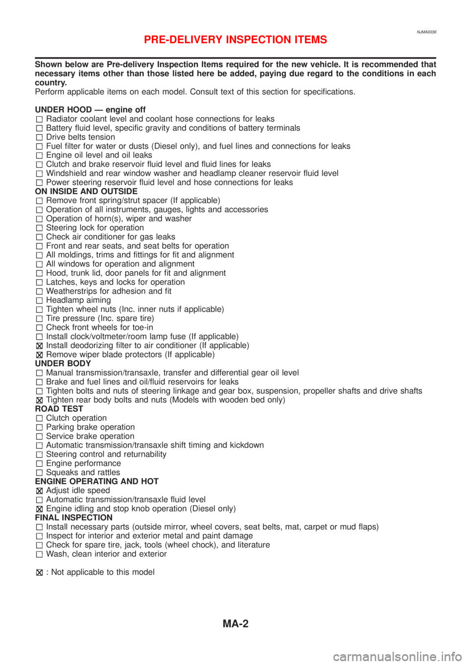
Shown below are Pre-delivery Inspection Items required for the new vehicle. It is recommended that
necessary items other than those listed here be added, paying due regard to the conditions in each
country.
Perform applicable items on each model. Consult text of this section for specifications.
UNDER HOOD Ð engine off
Radiator coolant level and coolant hose connections for leaks
Battery fluid level, specific gravity and conditions of battery terminals
Drive belts tension
Fuel filter for water or dusts (Diesel only), and fuel lines and connections for leaks
Engine oil level and oil leaks
Clutch and brake reservoir fluid level and fluid lines for leaks
Windshield and rear window washer and headlamp cleaner reservoir fluid level
Power steering reservoir fluid level and hose connections for leaks
ON INSIDE AND OUTSIDE
Remove front spring/strut spacer (If applicable)
Operation of all instruments, gauges, lights and accessories
Operation of horn(s), wiper and washer
Steering lock for operation
Check air conditioner for gas leaks
Front and rear seats, and seat belts for operation
All moldings, trims and fittings for fit and alignment
All windows for operation and alignment
Hood, trunk lid, door panels for fit and alignment
Latches, keys and locks for operation
Weatherstrips for adhesion and fit
Headlamp aiming
Tighten wheel nuts (Inc. inner nuts if applicable)
Tire pressure (Inc. spare tire)
Check front wheels for toe-in
Install clock/voltmeter/room lamp fuse (If applicable)
Install deodorizing filter to air conditioner (If applicable)
Remove wiper blade protectors (If applicable)
UNDER BODY
Manual transmission/transaxle, transfer and differential gear oil level
Brake and fuel lines and oil/fluid reservoirs for leaks
Tighten bolts and nuts of steering linkage and gear box, suspension, propeller shafts and drive shafts
Tighten rear body bolts and nuts (Models with wooden bed only)
ROAD TEST
Clutch operation
Parking brake operation
Service brake operation
Automatic transmission/transaxle shift timing and kickdown
Steering control and returnability
Engine performance
Squeaks and rattles
ENGINE OPERATING AND HOT
Adjust idle speed
Automatic transmission/transaxle fluid level
Engine idling and stop knob operation (Diesel only)
FINAL INSPECTION
Install necessary parts (outside mirror, wheel covers, seat belts, mat, carpet or mud flaps)
Inspect for interior and exterior metal and paint damage
Check for spare tire, jack, tools (wheel chock), and literature
Wash, clean interior and exterior
: Not applicable to this model
PRE-DELIVERY INSPECTION ITEMS
MA-2
Page 81 of 2493
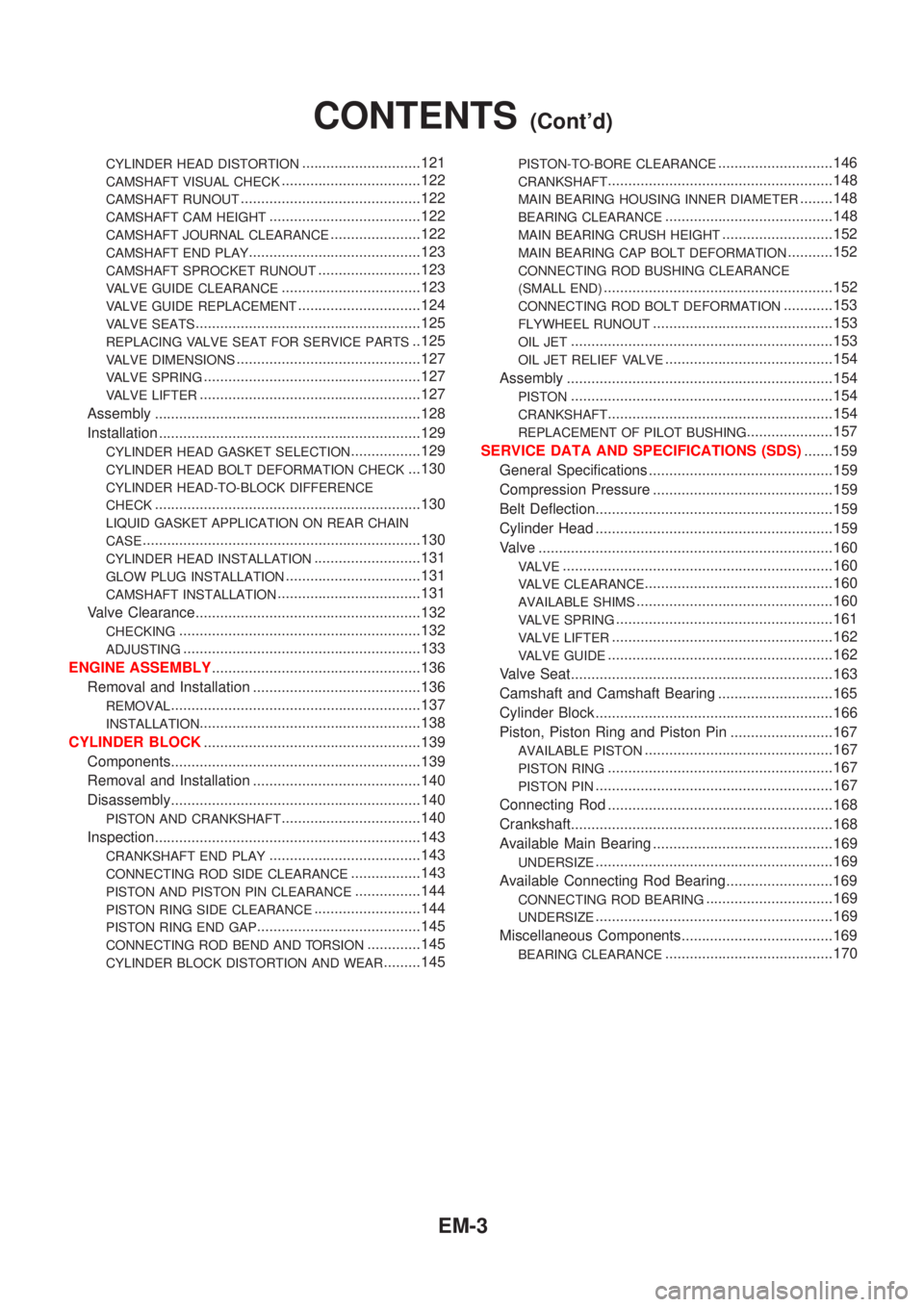
CYLINDER HEAD DISTORTION.............................121
CAMSHAFT VISUAL CHECK..................................122
CAMSHAFT RUNOUT............................................122
CAMSHAFT CAM HEIGHT.....................................122
CAMSHAFT JOURNAL CLEARANCE......................122
CAMSHAFT END PLAY..........................................123
CAMSHAFT SPROCKET RUNOUT.........................123
VALVE GUIDE CLEARANCE..................................123
VALVE GUIDE REPLACEMENT..............................124
VALVE SEATS.......................................................125
REPLACING VALVE SEAT FOR SERVICE PARTS..125
VALVE DIMENSIONS.............................................127
VALVE SPRING.....................................................127
VALVE LIFTER......................................................127
Assembly .................................................................128
Installation ................................................................129
CYLINDER HEAD GASKET SELECTION.................129
CYLINDER HEAD BOLT DEFORMATION CHECK...130
CYLINDER HEAD-TO-BLOCK DIFFERENCE
CHECK
.................................................................130
LIQUID GASKET APPLICATION ON REAR CHAIN
CASE
....................................................................130
CYLINDER HEAD INSTALLATION..........................131
GLOW PLUG INSTALLATION.................................131
CAMSHAFT INSTALLATION...................................131
Valve Clearance.......................................................132
CHECKING...........................................................132
ADJUSTING..........................................................133
ENGINE ASSEMBLY...................................................136
Removal and Installation .........................................136
REMOVAL.............................................................137
INSTALLATION......................................................138
CYLINDER BLOCK.....................................................139
Components.............................................................139
Removal and Installation .........................................140
Disassembly.............................................................140
PISTON AND CRANKSHAFT..................................140
Inspection.................................................................143
CRANKSHAFT END PLAY.....................................143
CONNECTING ROD SIDE CLEARANCE.................143
PISTON AND PISTON PIN CLEARANCE................144
PISTON RING SIDE CLEARANCE..........................144
PISTON RING END GAP........................................145
CONNECTING ROD BEND AND TORSION.............145
CYLINDER BLOCK DISTORTION AND WEAR.........145
PISTON-TO-BORE CLEARANCE............................146
CRANKSHAFT.......................................................148
MAIN BEARING HOUSING INNER DIAMETER........148
BEARING CLEARANCE.........................................148
MAIN BEARING CRUSH HEIGHT...........................152
MAIN BEARING CAP BOLT DEFORMATION...........152
CONNECTING ROD BUSHING CLEARANCE
(SMALL END)
........................................................152
CONNECTING ROD BOLT DEFORMATION............153
FLYWHEEL RUNOUT............................................153
OIL JET................................................................153
OIL JET RELIEF VALVE.........................................154
Assembly .................................................................154
PISTON................................................................154
CRANKSHAFT.......................................................154
REPLACEMENT OF PILOT BUSHING.....................157
SERVICE DATA AND SPECIFICATIONS (SDS).......159
General Specifications .............................................159
Compression Pressure ............................................159
Belt Deflection..........................................................159
Cylinder Head ..........................................................159
Valve ........................................................................160
VALVE..................................................................160
VALVE CLEARANCE..............................................160
AVAILABLE SHIMS................................................160
VALVE SPRING.....................................................161
VALVE LIFTER......................................................162
VALVE GUIDE.......................................................162
Valve Seat................................................................163
Camshaft and Camshaft Bearing ............................165
Cylinder Block ..........................................................166
Piston, Piston Ring and Piston Pin .........................167
AVAILABLE PISTON..............................................167
PISTON RING.......................................................167
PISTON PIN..........................................................167
Connecting Rod .......................................................168
Crankshaft................................................................168
Available Main Bearing ............................................169
UNDERSIZE..........................................................169
Available Connecting Rod Bearing..........................169
CONNECTING ROD BEARING...............................169
UNDERSIZE..........................................................169
Miscellaneous Components.....................................169
BEARING CLEARANCE.........................................170
CONTENTS(Cont'd)
EM-3
Page 92 of 2493
NJEM0007
1. Warm up engine.
2. Turn ignition switch OFF.
3. Release fuel pressure.
Refer to EC-38, ªReleasing Fuel Pressureº.
4. Remove ignition coils.
5. Remove spark plugs.
+Clean area around plug with compressed air before removing
the spark plug.
SEM973E
AEM308
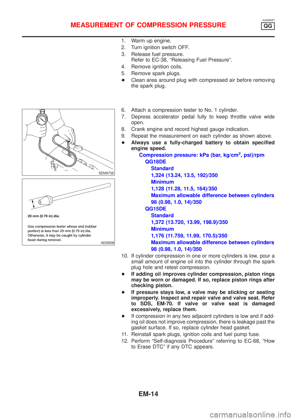
6. Attach a compression tester to No. 1 cylinder.
7. Depress accelerator pedal fully to keep throttle valve wide
open.
8. Crank engine and record highest gauge indication.
9. Repeat the measurement on each cylinder as shown above.
+Always use a fully-charged battery to obtain specified
engine speed.
Compression pressure: kPa (bar, kg/cm
2, psi)/rpm
QG18DE
Standard
1,324 (13.24, 13.5, 192)/350
Minimum
1,128 (11.28, 11.5, 164)/350
Maximum allowable difference between cylinders
98 (0.98, 1.0, 14)/350
QG15DE
Standard
1,372 (13.720, 13.99, 198.9)/350
Minimum
1,176 (11.759, 11.99, 170.5)/350
Maximum allowable difference between cylinders
98 (0.98, 1.0, 14)/350
10. If cylinder compression in one or more cylinders is low, pour a
small amount of engine oil into the cylinder through the spark
plug hole and retest compression.
+If adding oil improves cylinder compression, piston rings
may be worn or damaged. If so, replace piston rings after
checking piston.
+If pressure stays low, a valve may be sticking or seating
improperly. Inspect and repair valve and valve seat. Refer
to SDS, EM-70. If valve or valve seat is damaged
excessively, replace them.
+If compression in any two adjacent cylinders is low and if add-
ing oil does not improve compression, there is leakage past the
gasket surface. If so, replace cylinder head gasket.
11. Reinstall spark plugs, ignition coils and fuel pump fuse.
12. Perform ªSelf-diagnosis Procedureº referring to EC-68, ªHow
to Erase DTCº if any DTC appears.
MEASUREMENT OF COMPRESSION PRESSUREQG
EM-14
Page 101 of 2493
CAUTION:
+After removing timing chain, do not turn crankshaft and
camshaft separately, or valves will strike piston heads.
+When installing chain tensioner, oil seats, or other sliding
parts, lubricate contacting surfaces with new engine oil.
+Apply new engine oil to bolt threads and seat surfaces
when installing camshaft sprocket and crankshaft pulley.
+When removing oil pump assembly, remove camshaft
position sensor (PHASE), then remove timing chain from
engine.
+Be careful not to damage sensor edges.
SEM869F
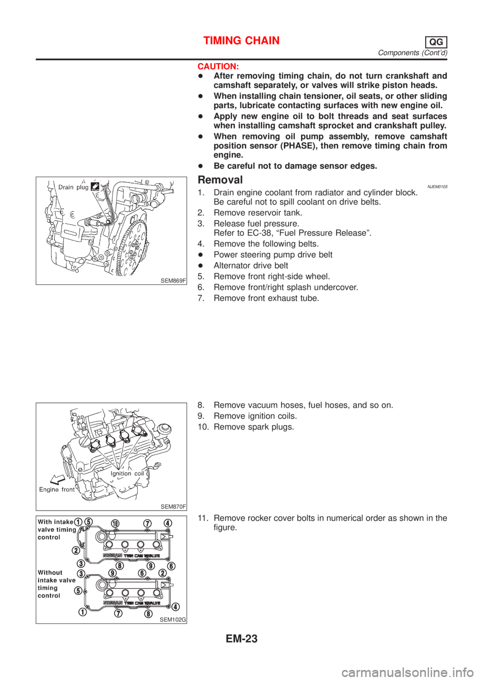
RemovalNJEM01051. Drain engine coolant from radiator and cylinder block.
Be careful not to spill coolant on drive belts.
2. Remove reservoir tank.
3. Release fuel pressure.
Refer to EC-38, ªFuel Pressure Releaseº.
4. Remove the following belts.
+Power steering pump drive belt
+Alternator drive belt
5. Remove front right-side wheel.
6. Remove front/right splash undercover.
7. Remove front exhaust tube.
SEM870F
8. Remove vacuum hoses, fuel hoses, and so on.
9. Remove ignition coils.
10. Remove spark plugs.
SEM102G
11. Remove rocker cover bolts in numerical order as shown in the
figure.
TIMING CHAINQG
Components (Cont'd)
EM-23
Page 192 of 2493
SEM270G
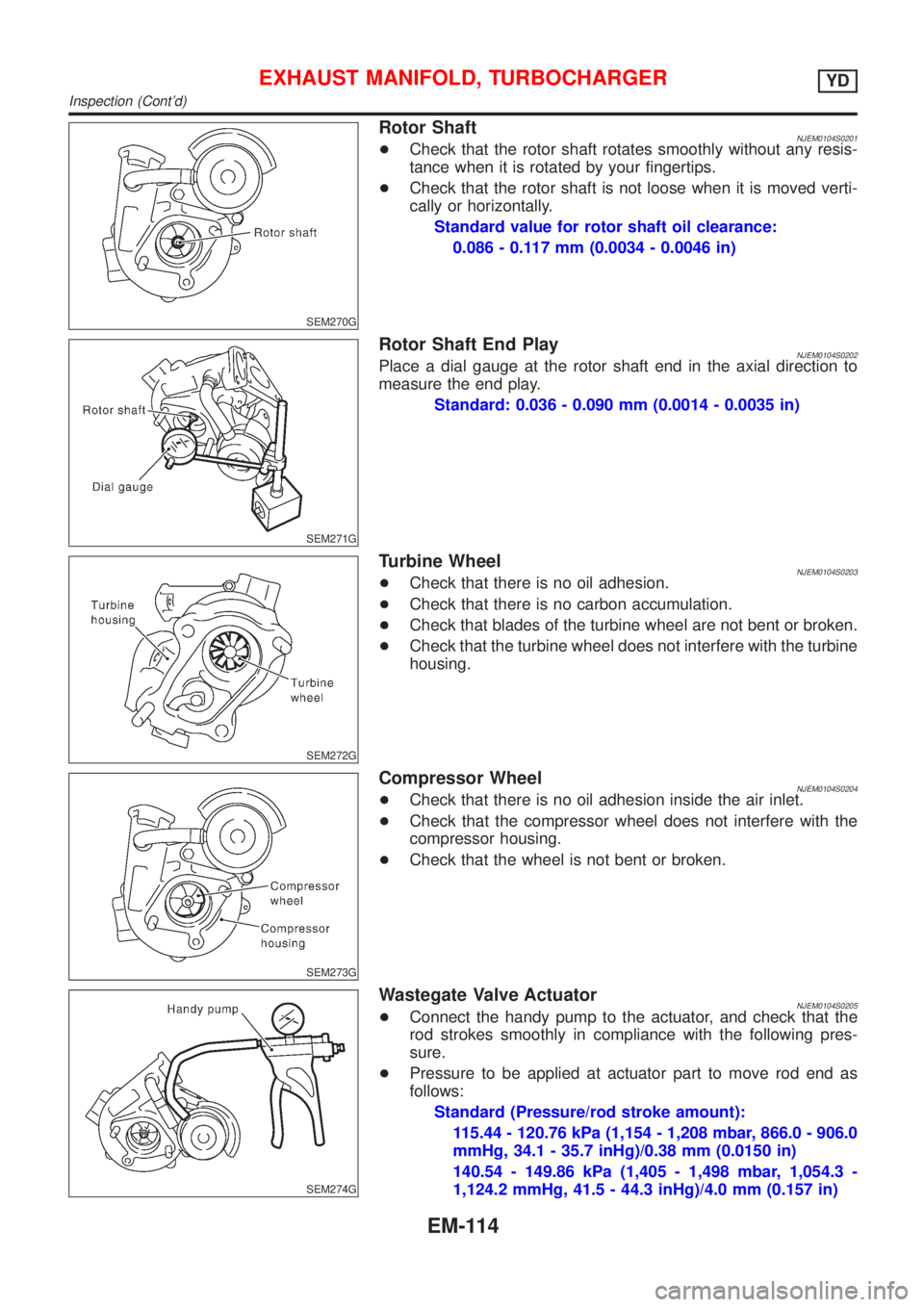
Rotor ShaftNJEM0104S0201+Check that the rotor shaft rotates smoothly without any resis-
tance when it is rotated by your fingertips.
+Check that the rotor shaft is not loose when it is moved verti-
cally or horizontally.
Standard value for rotor shaft oil clearance:
0.086 - 0.117 mm (0.0034 - 0.0046 in)
SEM271G
Rotor Shaft End PlayNJEM0104S0202Place a dial gauge at the rotor shaft end in the axial direction to
measure the end play.
Standard: 0.036 - 0.090 mm (0.0014 - 0.0035 in)
SEM272G
Turbine WheelNJEM0104S0203+Check that there is no oil adhesion.
+Check that there is no carbon accumulation.
+Check that blades of the turbine wheel are not bent or broken.
+Check that the turbine wheel does not interfere with the turbine
housing.
SEM273G
Compressor WheelNJEM0104S0204+Check that there is no oil adhesion inside the air inlet.
+Check that the compressor wheel does not interfere with the
compressor housing.
+Check that the wheel is not bent or broken.
SEM274G
Wastegate Valve ActuatorNJEM0104S0205+Connect the handy pump to the actuator, and check that the
rod strokes smoothly in compliance with the following pres-
sure.
+Pressure to be applied at actuator part to move rod end as
follows:
Standard (Pressure/rod stroke amount):
115.44 - 120.76 kPa (1,154 - 1,208 mbar, 866.0 - 906.0
mmHg, 34.1 - 35.7 inHg)/0.38 mm (0.0150 in)
140.54 - 149.86 kPa (1,405 - 1,498 mbar, 1,054.3 -
1,124.2 mmHg, 41.5 - 44.3 inHg)/4.0 mm (0.157 in)
EXHAUST MANIFOLD, TURBOCHARGERYD
Inspection (Cont'd)
EM-114
Page 197 of 2493
CAUTION:
+When installing camshafts, chain tensioners, oil seals, or
other sliding parts, lubricate contacting surfaces with new
engine oil.
+Apply new engine oil to threads and seat surfaces when
installing cylinder head, camshaft sprocket, crankshaft
pulley, and camshaft bracket.
+Attach tags to valve lifters so as not to mix them up.
RemovalNJEM0063PREPARATIVE WORKNJEM0063S011. Drain engine coolant. Refer to LC-43, ªChanging Engine Cool-
antº.
2. Remove exhaust manifold. Refer to EM-111, ªRemovalº.
3. Remove intake manifold. Refer to EM-107, ªRemovalº.
+Apply paint to camshaft sprockets for alignment during
installation.
JEM152G
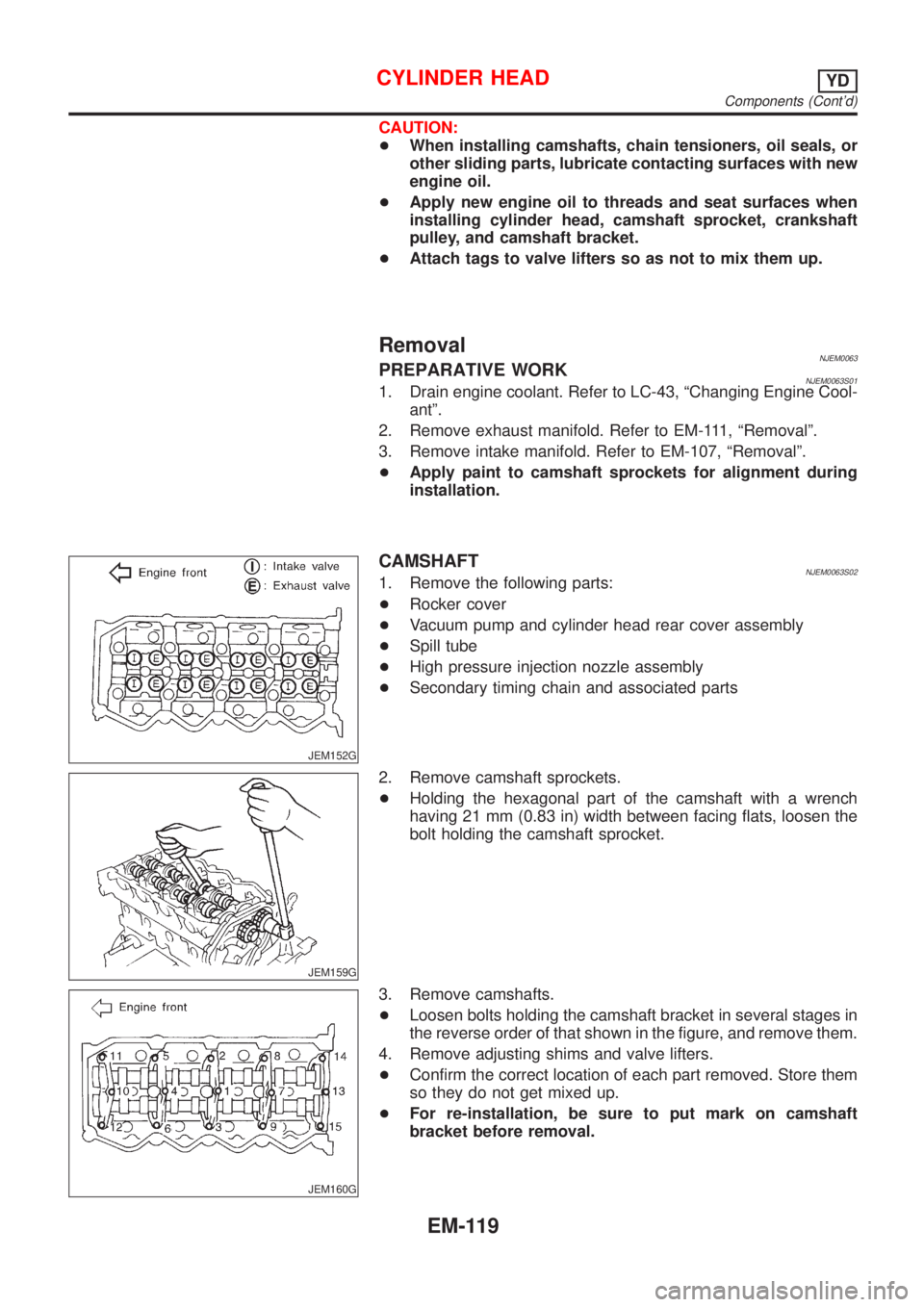
CAMSHAFTNJEM0063S021. Remove the following parts:
+Rocker cover
+Vacuum pump and cylinder head rear cover assembly
+Spill tube
+High pressure injection nozzle assembly
+Secondary timing chain and associated parts
JEM159G
2. Remove camshaft sprockets.
+Holding the hexagonal part of the camshaft with a wrench
having 21 mm (0.83 in) width between facing flats, loosen the
bolt holding the camshaft sprocket.
JEM160G
3. Remove camshafts.
+Loosen bolts holding the camshaft bracket in several stages in
the reverse order of that shown in the figure, and remove them.
4. Remove adjusting shims and valve lifters.
+Confirm the correct location of each part removed. Store them
so they do not get mixed up.
+For re-installation, be sure to put mark on camshaft
bracket before removal.
CYLINDER HEADYD
Components (Cont'd)
EM-119
Page 219 of 2493
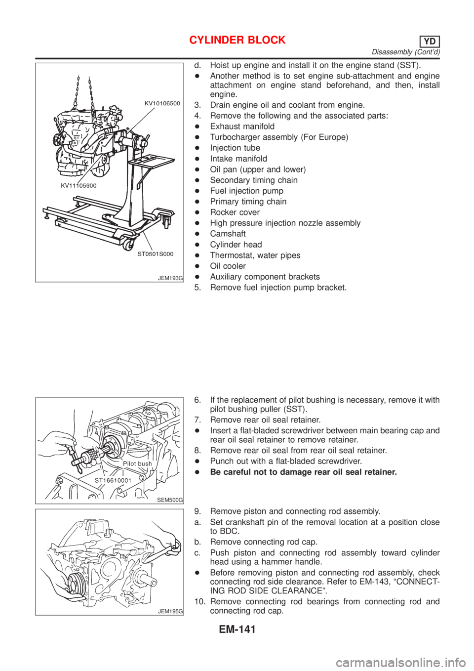
JEM193G
d. Hoist up engine and install it on the engine stand (SST).
+Another method is to set engine sub-attachment and engine
attachment on engine stand beforehand, and then, install
engine.
3. Drain engine oil and coolant from engine.
4. Remove the following and the associated parts:
+Exhaust manifold
+Turbocharger assembly (For Europe)
+Injection tube
+Intake manifold
+Oil pan (upper and lower)
+Secondary timing chain
+Fuel injection pump
+Primary timing chain
+Rocker cover
+High pressure injection nozzle assembly
+Camshaft
+Cylinder head
+Thermostat, water pipes
+Oil cooler
+Auxiliary component brackets
5. Remove fuel injection pump bracket.
SEM500G
6. If the replacement of pilot bushing is necessary, remove it with
pilot bushing puller (SST).
7. Remove rear oil seal retainer.
+Insert a flat-bladed screwdriver between main bearing cap and
rear oil seal retainer to remove retainer.
8. Remove rear oil seal from rear oil seal retainer.
+Punch out with a flat-bladed screwdriver.
+Be careful not to damage rear oil seal retainer.
JEM195G
9. Remove piston and connecting rod assembly.
a. Set crankshaft pin of the removal location at a position close
to BDC.
b. Remove connecting rod cap.
c. Push piston and connecting rod assembly toward cylinder
head using a hammer handle.
+Before removing piston and connecting rod assembly, check
connecting rod side clearance. Refer to EM-143, ªCONNECT-
ING ROD SIDE CLEARANCEº.
10. Remove connecting rod bearings from connecting rod and
connecting rod cap.
CYLINDER BLOCKYD
Disassembly (Cont'd)
EM-141
Page 237 of 2493
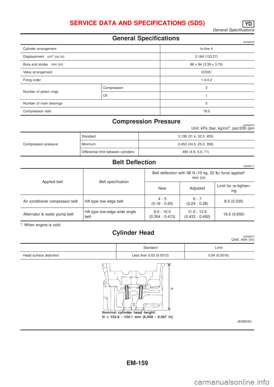
General SpecificationsNJEM0075
Cylinder arrangementIn-line 4
Displacement cm
3(cu in)2,184 (133.27)
Bore and stroke mm (in)86 x 94 (3.39 x 3.70)
Valve arrangementDOHC
Firing order1-3-4-2
Number of piston ringsCompression 2
Oil 1
Number of main bearings5
Compression ratio18.0
Compression PressureNJEM0076Unit: kPa (bar, kg/cm2, psi)/200 rpm
Compression pressureStandard 3,138 (31.4, 32.0, 455)
Minimum 2,452 (24.5, 25.0, 356)
Differential limit between cylinders 490 (4.9, 5.0, 71)
Belt DeflectionNJEM0111
Applied belt Belt specificationBelt deflection with 98 N (10 kg, 22 lb) force applied*
mm (in)
New AdjustedLimit for re-tighten-
ing
Air conditioner compressor belt HA type low edge belt4-5
(0.16 - 0.20)6-7
(0.24 - 0.28)8.5 (0.335)
Alternator & water pump beltHA type low-edge wide angle
belt9.0 - 10.5
(0.354 - 0.413)11.0 - 12.5
(0.433 - 0.492)16.5 (0.650)
*: When engine is cold.
Cylinder HeadNJEM0077Unit: mm (in)
Standard Limit
Head surface distortion Less than 0.03 (0.0012) 0.04 (0.0016)
JEM204G
SERVICE DATA AND SPECIFICATIONS (SDS)YD
General Specifications
EM-159
Page 255 of 2493
SEM855F
SEM856F
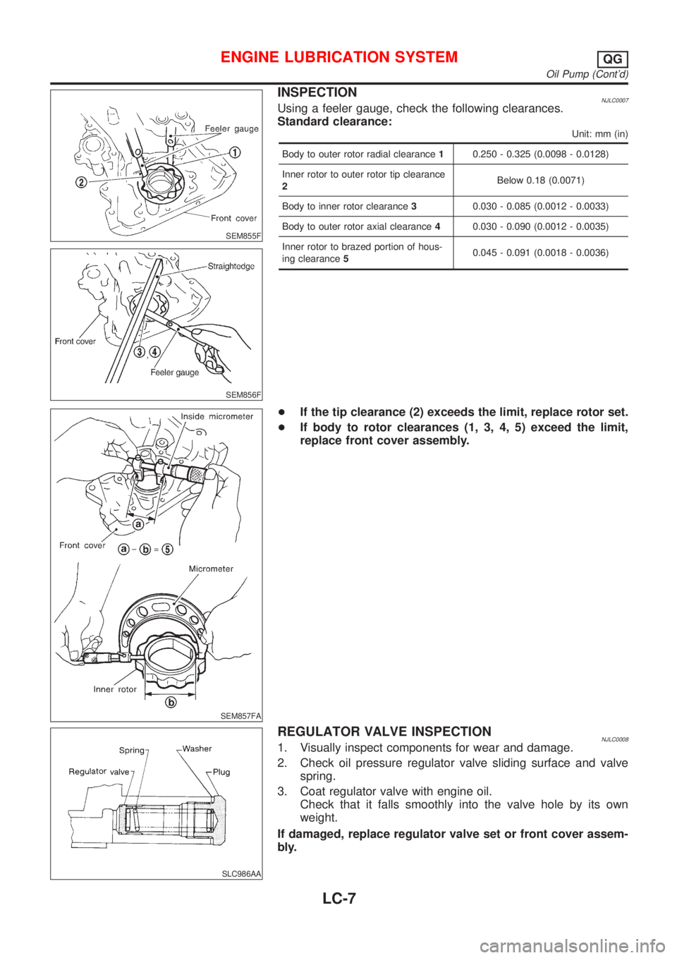
INSPECTIONNJLC0007Using a feeler gauge, check the following clearances.
Standard clearance:
Unit: mm (in)
Body to outer rotor radial clearance10.250 - 0.325 (0.0098 - 0.0128)
Inner rotor to outer rotor tip clearance
2Below 0.18 (0.0071)
Body to inner rotor clearance30.030 - 0.085 (0.0012 - 0.0033)
Body to outer rotor axial clearance40.030 - 0.090 (0.0012 - 0.0035)
Inner rotor to brazed portion of hous-
ing clearance50.045 - 0.091 (0.0018 - 0.0036)
SEM857FA
+If the tip clearance (2) exceeds the limit, replace rotor set.
+If body to rotor clearances (1, 3, 4, 5) exceed the limit,
replace front cover assembly.
SLC986AA
REGULATOR VALVE INSPECTIONNJLC00081. Visually inspect components for wear and damage.
2. Check oil pressure regulator valve sliding surface and valve
spring.
3. Coat regulator valve with engine oil.
Check that it falls smoothly into the valve hole by its own
weight.
If damaged, replace regulator valve set or front cover assem-
bly.
ENGINE LUBRICATION SYSTEMQG
Oil Pump (Cont'd)
LC-7
Page 258 of 2493
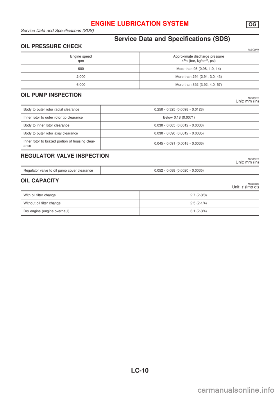
Service Data and Specifications (SDS)
OIL PRESSURE CHECKNJLC0011
Engine speed
rpmApproximate discharge pressure
kPa (bar, kg/cm2, psi)
600 More than 98 (0.98, 1.0, 14)
2,000 More than 294 (2.94, 3.0, 43)
6,000 More than 392 (3.92, 4.0, 57)
OIL PUMP INSPECTIONNJLC0013Unit: mm (in)
Body to outer rotor radial clearance 0.250 - 0.325 (0.0098 - 0.0128)
Inner rotor to outer rotor tip clearance Below 0.18 (0.0071)
Body to inner rotor clearance 0.030 - 0.085 (0.0012 - 0.0033)
Body to outer rotor axial clearance 0.030 - 0.090 (0.0012 - 0.0035)
Inner rotor to brazed portion of housing clear-
ance0.045 - 0.091 (0.0018 - 0.0036)
REGULATOR VALVE INSPECTIONNJLC0012Unit: mm (in)
Regulator valve to oil pump cover clearance 0.052 - 0.088 (0.0020 - 0.0035)
OIL CAPACITYNJLC0036Unit:!(Imp qt)
With oil filter change2.7 (2-3/8)
Without oil filter change2.5 (2-1/4)
Dry engine (engine overhaul)3.1 (2-3/4)
ENGINE LUBRICATION SYSTEMQG
Service Data and Specifications (SDS)
LC-10