power steering fluid NISSAN ALMERA N16 2001 Electronic Repair Manual
[x] Cancel search | Manufacturer: NISSAN, Model Year: 2001, Model line: ALMERA N16, Model: NISSAN ALMERA N16 2001Pages: 2493, PDF Size: 66.97 MB
Page 13 of 2493
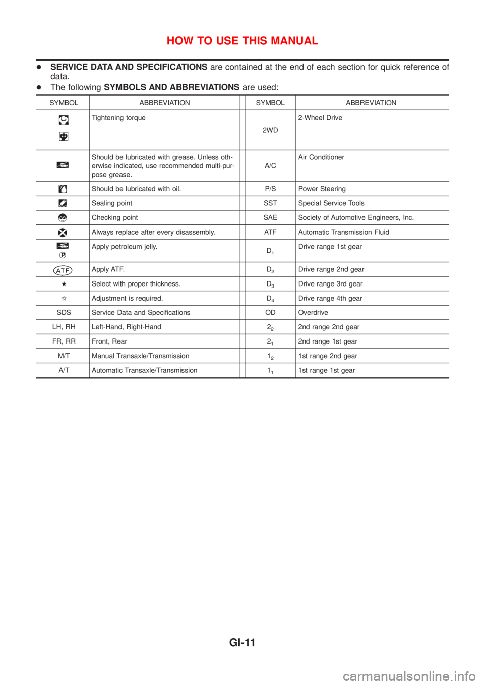
+SERVICE DATA AND SPECIFICATIONSare contained at the end of each section for quick reference of
data.
+The followingSYMBOLS AND ABBREVIATIONSare used:
SYMBOL ABBREVIATION SYMBOL ABBREVIATION
Tightening torque
2WD2-Wheel Drive
Should be lubricated with grease. Unless oth-
erwise indicated, use recommended multi-pur-
pose grease.A/CAir Conditioner
Should be lubricated with oil. P/S Power Steering
Sealing point SST Special Service Tools
Checking point SAE Society of Automotive Engineers, Inc.
Always replace after every disassembly. ATF Automatic Transmission Fluid
jP
Apply petroleum jelly.
D1Drive range 1st gear
Apply ATF. D2Drive range 2nd gear
HSelect with proper thickness. D
3Drive range 3rd gear
IAdjustment is required. D
4Drive range 4th gear
SDS Service Data and Specifications OD Overdrive
LH, RH Left-Hand, Right-Hand 2
22nd range 2nd gear
FR, RR Front, Rear 2
12nd range 1st gear
M/T Manual Transaxle/Transmission 1
21st range 2nd gear
A/T Automatic Transaxle/Transmission 1
11st range 1st gear
HOW TO USE THIS MANUAL
GI-11
Page 58 of 2493
NJMA0036
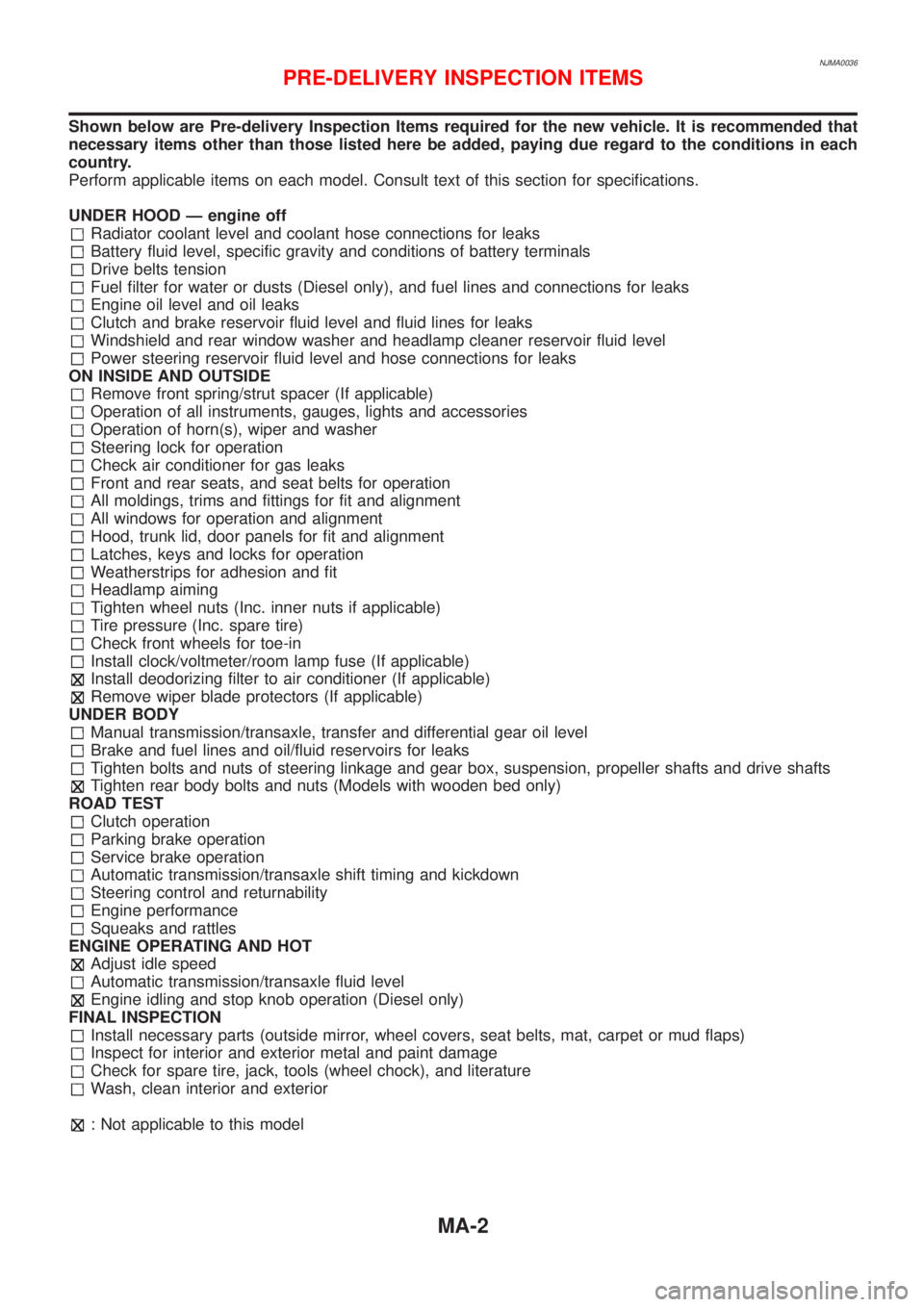
Shown below are Pre-delivery Inspection Items required for the new vehicle. It is recommended that
necessary items other than those listed here be added, paying due regard to the conditions in each
country.
Perform applicable items on each model. Consult text of this section for specifications.
UNDER HOOD Ð engine off
Radiator coolant level and coolant hose connections for leaks
Battery fluid level, specific gravity and conditions of battery terminals
Drive belts tension
Fuel filter for water or dusts (Diesel only), and fuel lines and connections for leaks
Engine oil level and oil leaks
Clutch and brake reservoir fluid level and fluid lines for leaks
Windshield and rear window washer and headlamp cleaner reservoir fluid level
Power steering reservoir fluid level and hose connections for leaks
ON INSIDE AND OUTSIDE
Remove front spring/strut spacer (If applicable)
Operation of all instruments, gauges, lights and accessories
Operation of horn(s), wiper and washer
Steering lock for operation
Check air conditioner for gas leaks
Front and rear seats, and seat belts for operation
All moldings, trims and fittings for fit and alignment
All windows for operation and alignment
Hood, trunk lid, door panels for fit and alignment
Latches, keys and locks for operation
Weatherstrips for adhesion and fit
Headlamp aiming
Tighten wheel nuts (Inc. inner nuts if applicable)
Tire pressure (Inc. spare tire)
Check front wheels for toe-in
Install clock/voltmeter/room lamp fuse (If applicable)
Install deodorizing filter to air conditioner (If applicable)
Remove wiper blade protectors (If applicable)
UNDER BODY
Manual transmission/transaxle, transfer and differential gear oil level
Brake and fuel lines and oil/fluid reservoirs for leaks
Tighten bolts and nuts of steering linkage and gear box, suspension, propeller shafts and drive shafts
Tighten rear body bolts and nuts (Models with wooden bed only)
ROAD TEST
Clutch operation
Parking brake operation
Service brake operation
Automatic transmission/transaxle shift timing and kickdown
Steering control and returnability
Engine performance
Squeaks and rattles
ENGINE OPERATING AND HOT
Adjust idle speed
Automatic transmission/transaxle fluid level
Engine idling and stop knob operation (Diesel only)
FINAL INSPECTION
Install necessary parts (outside mirror, wheel covers, seat belts, mat, carpet or mud flaps)
Inspect for interior and exterior metal and paint damage
Check for spare tire, jack, tools (wheel chock), and literature
Wash, clean interior and exterior
: Not applicable to this model
PRE-DELIVERY INSPECTION ITEMS
MA-2
Page 62 of 2493
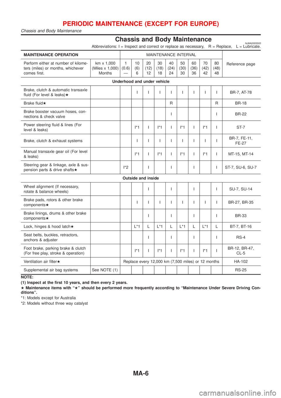
Chassis and Body MaintenanceNJMA0005S05Abbreviations: I = Inspect and correct or replace as necessary, R = Replace, L = Lubricate.
MAINTENANCE OPERATIONMAINTENANCE INTERVAL
Reference page Perform either at number of kilome-
ters (miles) or months, whichever
comes first.km x 1,000
(Miles x 1,000)
Months1
(0.6)
Ð10
(6)
620
(12)
1230
(18)
1840
(24)
2450
(30)
3060
(36)
3670
(42)
4280
(48)
48
Underhood and under vehicle
Brake, clutch & automatic transaxle
fluid (For level & leaks)HIIIIIIIIBR-7, AT-78
Brake fluidHR R BR-18
Brake booster vacuum hoses, con-
nections & check valveI I BR-22
Power steering fluid & lines (For
level & leaks)I*1 I I*1 I I*1 I I*1 I ST-7
Brake, clutch & exhaust systemsIIIIIIIIBR-7, FE-11,
FE-27
Manual transaxle gear oil (For level
& leaks)I*1 I I*1 I I*1 I I*1 I MT-15, MT-14
Steering gear & linkage, axle & sus-
pension parts & drive shaftsHI*2IIIIST-7,SU-6, SU-7
Outside and inside
Wheel alignment (If necessary,
rotate & balance wheels)IIIISU-7, SU-14
Brake pads, rotors & other brake
componentsHIIIIIIIIBR-27, BR-35
Brake linings, drums & other brake
componentsHIIIIBR-33
Lock, hinges & hood latchHL*1 L L*1 L L*1 L L*1 L BT-7, BT-16
Seat belts, buckles, retractors,
anchors & adjusterIIIIRS-4
Foot brake, parking brake & clutch
(For free play, stroke & operation)I*1 I I*1 I I*1 I I*1 IBR-12, BR-47,
CL-5
Ventilation air filterHReplace every 12,000 km (7,500 miles) or 12 months HA-102
Supplemental air bag systems See NOTE (1) RS-25
NOTE:
(1) Inspect at the first 10 years, and then every 2 years.
HMaintenance items with ªHº should be performed more frequently according to ªMaintenance Under Severe Driving Con-
ditionsº.
*1: Models except for Australia
*2: Models without three way catalyst
PERIODIC MAINTENANCE (EXCEPT FOR EUROPE)
Chassis and Body Maintenance
MA-6
Page 76 of 2493
NJMA0006
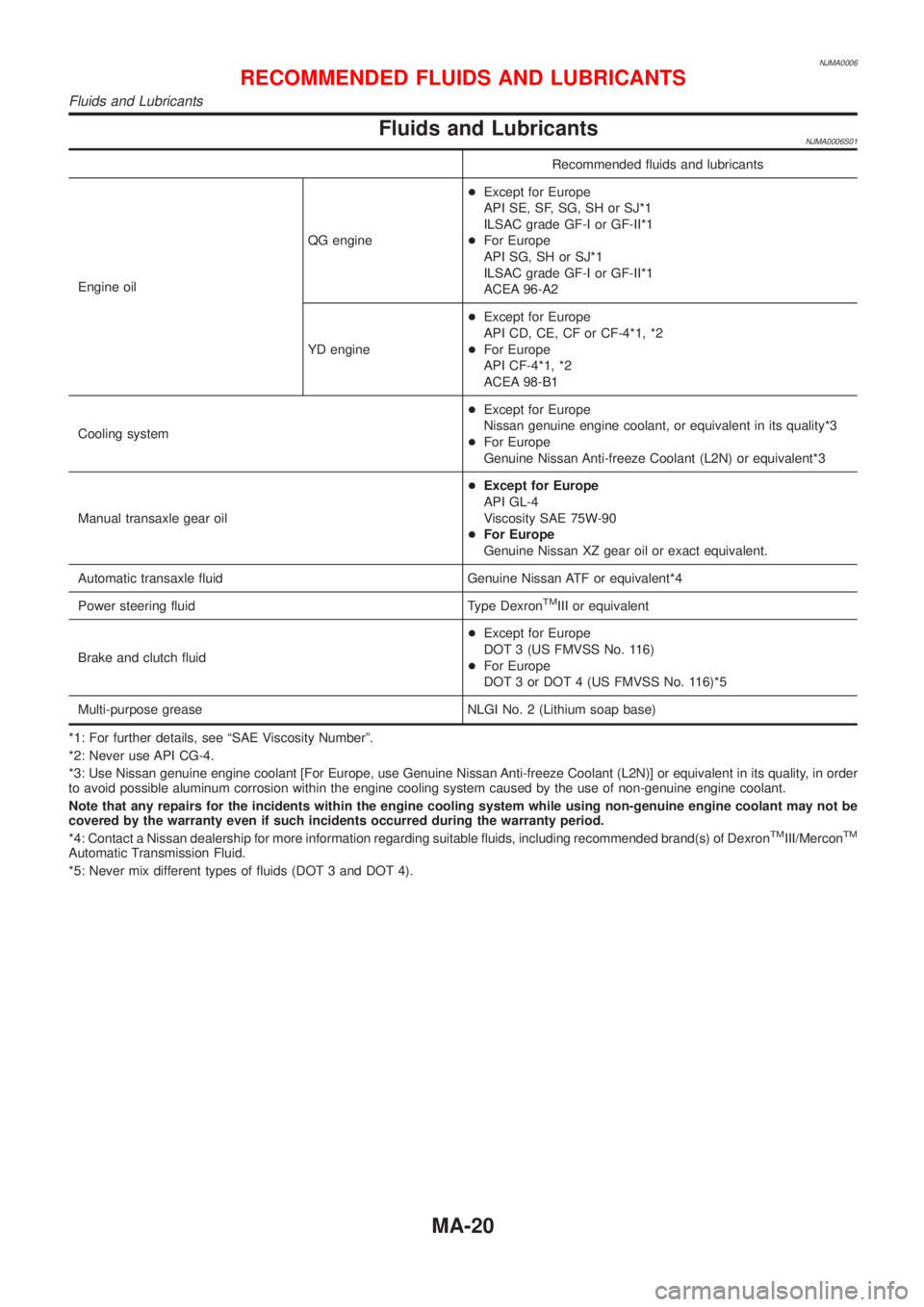
Fluids and LubricantsNJMA0006S01
Recommended fluids and lubricants
Engine oilQG engine+Except for Europe
API SE, SF, SG, SH or SJ*1
ILSAC grade GF-I or GF-II*1
+For Europe
API SG, SH or SJ*1
ILSAC grade GF-I or GF-II*1
ACEA 96-A2
YD engine+Except for Europe
API CD, CE, CF or CF-4*1, *2
+For Europe
API CF-4*1, *2
ACEA 98-B1
Cooling system+Except for Europe
Nissan genuine engine coolant, or equivalent in its quality*3
+For Europe
Genuine Nissan Anti-freeze Coolant (L2N) or equivalent*3
Manual transaxle gear oil+Except for Europe
API GL-4
Viscosity SAE 75W-90
+For Europe
Genuine Nissan XZ gear oil or exact equivalent.
Automatic transaxle fluid Genuine Nissan ATF or equivalent*4
Power steering fluid Type Dexron
TMIII or equivalent
Brake and clutch fluid+Except for Europe
DOT 3 (US FMVSS No. 116)
+For Europe
DOT 3 or DOT 4 (US FMVSS No. 116)*5
Multi-purpose grease NLGI No. 2 (Lithium soap base)
*1: For further details, see ªSAE Viscosity Numberº.
*2: Never use API CG-4.
*3: Use Nissan genuine engine coolant [For Europe, use Genuine Nissan Anti-freeze Coolant (L2N)] or equivalent in its quality, in order
to avoid possible aluminum corrosion within the engine cooling system caused by the use of non-genuine engine coolant.
Note that any repairs for the incidents within the engine cooling system while using non-genuine engine coolant may not be
covered by the warranty even if such incidents occurred during the warranty period.
*4: Contact a Nissan dealership for more information regarding suitable fluids, including recommended brand(s) of Dexron
TMIII/MerconTM
Automatic Transmission Fluid.
*5: Never mix different types of fluids (DOT 3 and DOT 4).
RECOMMENDED FLUIDS AND LUBRICANTS
Fluids and Lubricants
MA-20
Page 172 of 2493
JEM121G
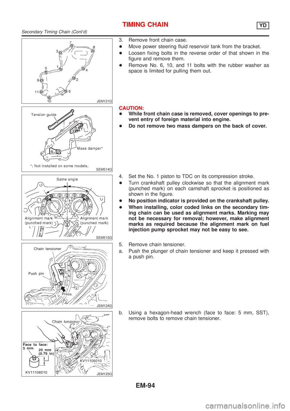
3. Remove front chain case.
+Move power steering fluid reservoir tank from the bracket.
+Loosen fixing bolts in the reverse order of that shown in the
figure and remove them.
+Remove No. 6, 10, and 11 bolts with the rubber washer as
space is limited for pulling them out.
SEM514G
CAUTION:
+While front chain case is removed, cover openings to pre-
vent entry of foreign material into engine.
+Do not remove two mass dampers on the back of cover.
SEM515G
4. Set the No. 1 piston to TDC on its compression stroke.
+Turn crankshaft pulley clockwise so that the alignment mark
(punched mark) on each camshaft sprocket is positioned as
shown in the figure.
+No position indicator is provided on the crankshaft pulley.
+When installing, color coded links on the secondary tim-
ing chain can be used as alignment marks. Marking may
not be necessary for removal; however, make alignment
marks as required because the alignment mark on fuel
injection pump sprocket may not be easy to see.
JEM124G
5. Remove chain tensioner.
a. Push the plunger of chain tensioner and keep it pressed with
a push pin.
JEM125G
b. Using a hexagon-head wrench (face to face: 5 mm, SST),
remove bolts to remove chain tensioner.
TIMING CHAINYD
Secondary Timing Chain (Cont'd)
EM-94
Page 215 of 2493
crankshaft position sensor (TDC sensor) from the assem-
bly.
+Always pay extra attention not to damage edge of crank-
shaft position sensor (TDC sensor) or ring gear teeth.
REMOVALNJEM0069S011. Remove engine undercover, and hood for hoisting.
2. Drain coolant from both cylinder block and radiator. Refer to
LC-43, ªChanging Engine Coolantº.
3. Remove the following parts:
+Battery
+RH and LH front wheels
+RH and LH splash covers (combined with undercover)
+Auxiliary belts
+Alternator
+Alternator brackets
+Radiator and cooling fan
+Engine cover
+Air ducts and air cleaner case
LH side of engine room:
4. Disconnect all harnesses and grounds that are connected to
components on vehicle.
5. Disconnect vacuum hose on vacuum pump side.
6. Disconnect fuel feed and fuel return hoses on engine side.
+Immediately put blind plugs into the openings to prevent
fuel from flowing out.
7. Disconnect heater hose. Plug opening of hose to prevent cool-
ant from flowing out.
RH side of engine room:
8. Remove air conditioner compressor from brackets and move
it toward vehicle side. Secure compressor on vehicle side with
rope.
Vehicle underside:
9. Remove exhaust front tube.
10. Disconnect two hoses from power steering pump and plug to
stop fluid.
11. Remove M/T control rod and support rod.
12. Remove ABS wheel sensor, and temporarily hang brake cali-
per with rope on vehicle side.
13. Remove RH and LH drive shafts.
YEM024
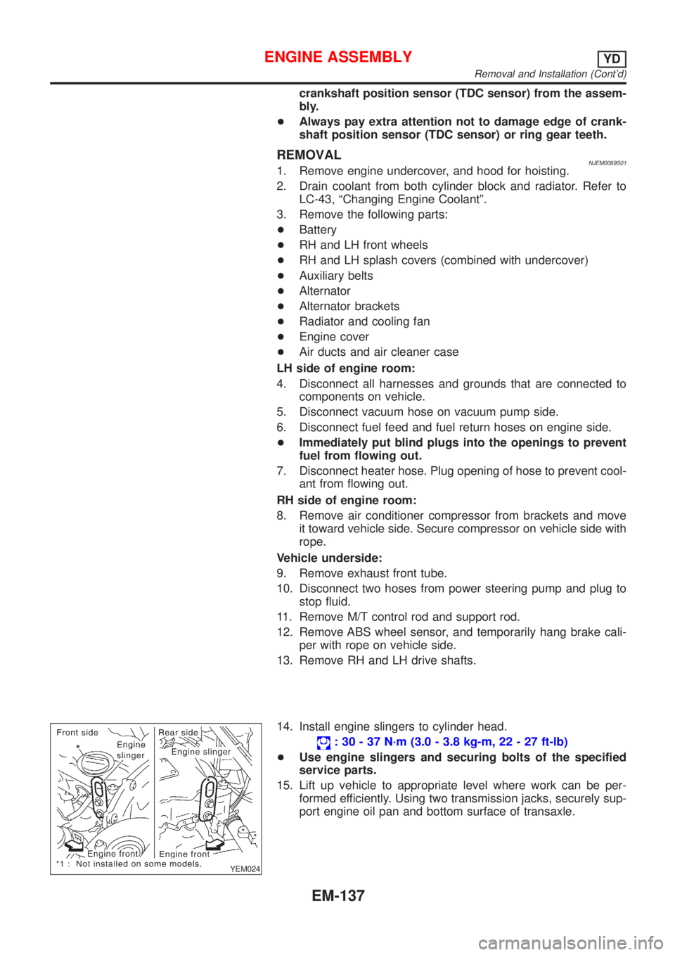
14. Install engine slingers to cylinder head.
: 30 - 37 N´m (3.0 - 3.8 kg-m, 22 - 27 ft-lb)
+Use engine slingers and securing bolts of the specified
service parts.
15. Lift up vehicle to appropriate level where work can be per-
formed efficiently. Using two transmission jacks, securely sup-
port engine oil pan and bottom surface of transaxle.
ENGINE ASSEMBLYYD
Removal and Installation (Cont'd)
EM-137
Page 720 of 2493
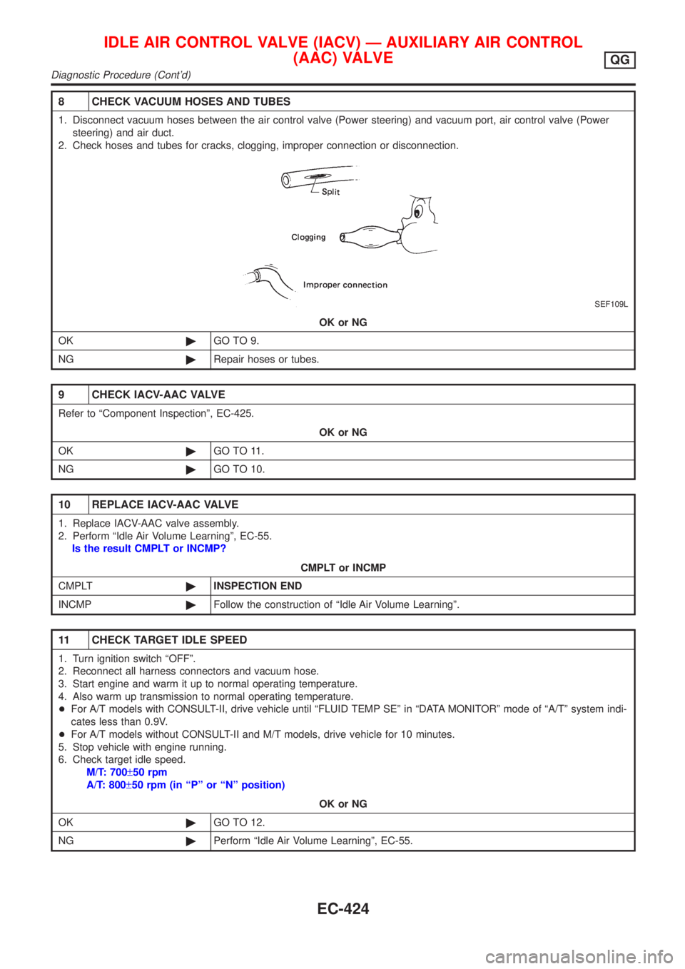
8 CHECK VACUUM HOSES AND TUBES
1. Disconnect vacuum hoses between the air control valve (Power steering) and vacuum port, air control valve (Power
steering) and air duct.
2. Check hoses and tubes for cracks, clogging, improper connection or disconnection.
SEF109L
OK or NG
OK©GO TO 9.
NG©Repair hoses or tubes.
9 CHECK IACV-AAC VALVE
Refer to ªComponent Inspectionº, EC-425.
OK or NG
OK©GO TO 11.
NG©GO TO 10.
10 REPLACE IACV-AAC VALVE
1. Replace IACV-AAC valve assembly.
2. Perform ªIdle Air Volume Learningº, EC-55.
Is the result CMPLT or INCMP?
CMPLT or INCMP
CMPLT©INSPECTION END
INCMP©Follow the construction of ªIdle Air Volume Learningº.
11 CHECK TARGET IDLE SPEED
1. Turn ignition switch ªOFFº.
2. Reconnect all harness connectors and vacuum hose.
3. Start engine and warm it up to normal operating temperature.
4. Also warm up transmission to normal operating temperature.
+For A/T models with CONSULT-II, drive vehicle until ªFLUID TEMP SEº in ªDATA MONITORº mode of ªA/Tº system indi-
cates less than 0.9V.
+For A/T models without CONSULT-II and M/T models, drive vehicle for 10 minutes.
5. Stop vehicle with engine running.
6. Check target idle speed.
M/T: 700±50 rpm
A/T: 800±50 rpm (in ªPº or ªNº position)
OK or NG
OK©GO TO 12.
NG©Perform ªIdle Air Volume Learningº, EC-55.
IDLE AIR CONTROL VALVE (IACV) Ð AUXILIARY AIR CONTROL
(AAC) VALVE
QG
Diagnostic Procedure (Cont'd)
EC-424
Page 810 of 2493
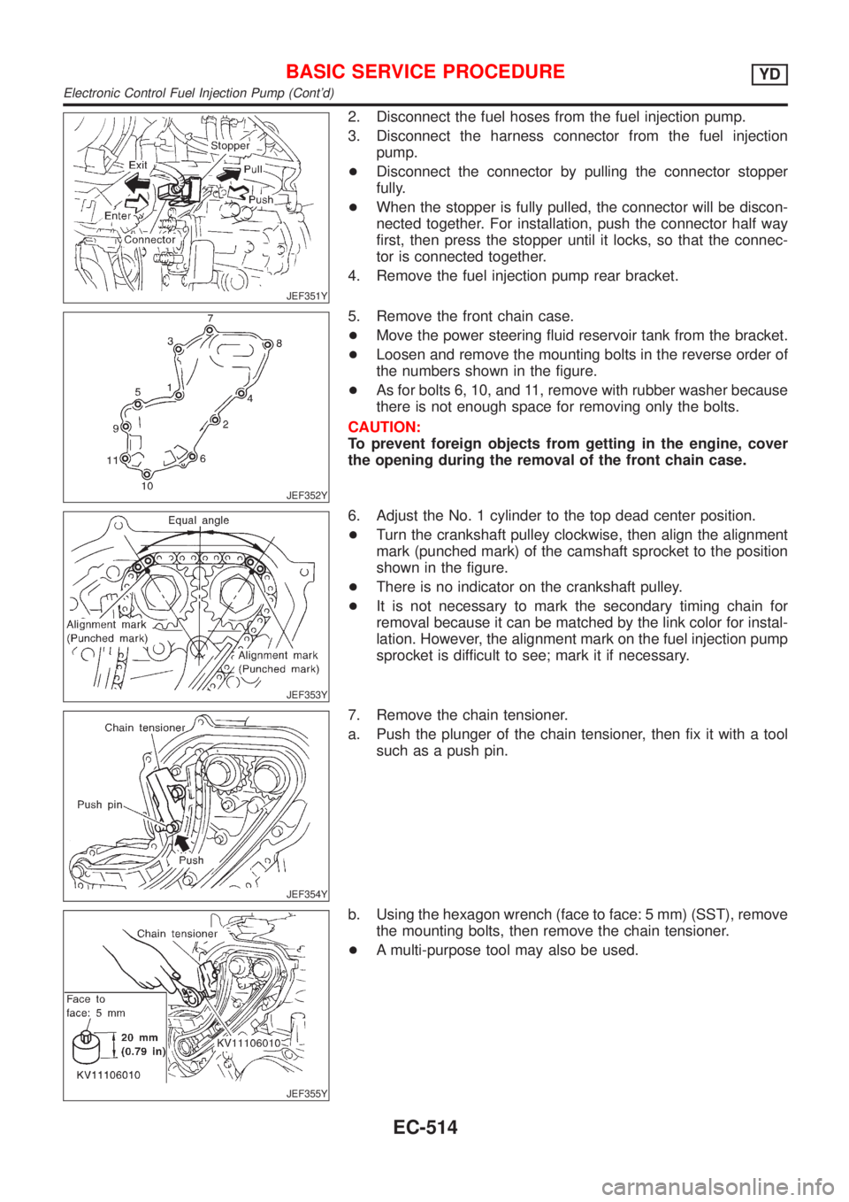
JEF351Y
2. Disconnect the fuel hoses from the fuel injection pump.
3. Disconnect the harness connector from the fuel injection
pump.
+Disconnect the connector by pulling the connector stopper
fully.
+When the stopper is fully pulled, the connector will be discon-
nected together. For installation, push the connector half way
first, then press the stopper until it locks, so that the connec-
tor is connected together.
4. Remove the fuel injection pump rear bracket.
JEF352Y
5. Remove the front chain case.
+Move the power steering fluid reservoir tank from the bracket.
+Loosen and remove the mounting bolts in the reverse order of
the numbers shown in the figure.
+As for bolts 6, 10, and 11, remove with rubber washer because
there is not enough space for removing only the bolts.
CAUTION:
To prevent foreign objects from getting in the engine, cover
the opening during the removal of the front chain case.
JEF353Y
6. Adjust the No. 1 cylinder to the top dead center position.
+Turn the crankshaft pulley clockwise, then align the alignment
mark (punched mark) of the camshaft sprocket to the position
shown in the figure.
+There is no indicator on the crankshaft pulley.
+It is not necessary to mark the secondary timing chain for
removal because it can be matched by the link color for instal-
lation. However, the alignment mark on the fuel injection pump
sprocket is difficult to see; mark it if necessary.
JEF354Y
7. Remove the chain tensioner.
a. Push the plunger of the chain tensioner, then fix it with a tool
such as a push pin.
JEF355Y
b. Using the hexagon wrench (face to face: 5 mm) (SST), remove
the mounting bolts, then remove the chain tensioner.
+A multi-purpose tool may also be used.
BASIC SERVICE PROCEDUREYD
Electronic Control Fuel Injection Pump (Cont'd)
EC-514
Page 1791 of 2493
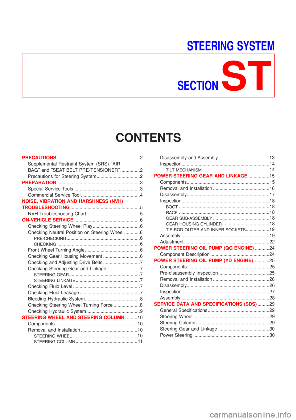
STEERING SYSTEM
SECTION
ST
CONTENTS
PRECAUTIONS...............................................................2
Supplemental Restraint System (SRS)²AIR
BAG²and²SEAT BELT PRE-TENSIONER²...............2
Precautions for Steering System .................................2
PREPARATION...............................................................3
Special Service Tools ..................................................3
Commercial Service Tool .............................................4
NOISE, VIBRATION AND HARSHNESS (NVH)
TROUBLESHOOTING.....................................................5
NVH Troubleshooting Chart.........................................5
ON-VEHICLE SERVICE..................................................6
Checking Steering Wheel Play ....................................6
Checking Neutral Position on Steering Wheel ............6
PRE-CHECKING........................................................6
CHECKING...............................................................6
Front Wheel Turning Angle ..........................................6
Checking Gear Housing Movement ............................6
Checking and Adjusting Drive Belts ............................7
Checking Steering Gear and Linkage .........................7
STEERING GEAR......................................................7
STEERING LINKAGE.................................................7
Checking Fluid Level ...................................................7
Checking Fluid Leakage ..............................................7
Bleeding Hydraulic System..........................................8
Checking Steering Wheel Turning Force ....................8
Checking Hydraulic System.........................................9
STEERING WHEEL AND STEERING COLUMN.........10
Components...............................................................10
Removal and Installation ...........................................10
STEERING WHEEL.................................................10
STEERING COLUMN............................................... 11Disassembly and Assembly .......................................13
Inspection...................................................................14
TILT MECHANISM...................................................14
POWER STEERING GEAR AND LINKAGE................15
Components...............................................................15
Removal and Installation ...........................................16
Disassembly...............................................................17
Inspection...................................................................18
BOOT.....................................................................18
RACK.....................................................................18
GEAR SUB-ASSEMBLY...........................................18
GEAR HOUSING CYLINDER....................................18
TIE-ROD OUTER AND INNER SOCKETS..................19
Assembly ...................................................................19
Adjustment .................................................................22
POWER STEERING OIL PUMP (QG ENGINE)...........24
Component Description .............................................24
POWER STEERING OIL PUMP (YD ENGINE)............25
Components...............................................................25
Pre-disassembly Inspection .......................................25
Removal and Installation ...........................................26
Disassembly...............................................................26
Inspection...................................................................27
Assembly ...................................................................28
SERVICE DATA AND SPECIFICATIONS (SDS).........29
General Specifications ...............................................29
Steering Wheel ..........................................................29
Steering Column ........................................................29
Steering Gear and Linkage .......................................30
Power Steering ..........................................................30
Page 1792 of 2493

Supplemental Restraint System (SRS) ªAIR
BAGº and ªSEAT BELT PRE-TENSIONERº
NJST0044The Supplemental Restraint System such as ªAIR BAGº and ªSEAT BELT PRE-TENSIONERº used along with
a seat belt, helps to reduce the risk or severity of injury to the driver and front passenger for certain types of
collision. The SRS system composition which is available to NISSAN MODEL N16 is as follows (The compo-
sition varies according to the destination and optional equipment.):
+For a frontal collision
The Supplemental Restraint System consists of driver air bag module (located in the center of the steer-
ing wheel), front passenger air bag module (located on the instrument panel on passenger side), front seat
belt pre-tensioners, a diagnosis sensor unit, warning lamp, wiring harness and spiral cable.
+For a side collision
The Supplemental Restraint System consists of front side air bag module (located in the outer side of front
seat), side air bag (satellite) sensor, diagnosis sensor unit (one of components of air bags for a frontal
collision), wiring harness, warning lamp (one of components of air bags for a frontal collision).
Information necessary to service the system safely is included in theRS sectionof this Service Manual.
WARNING:
+To avoid rendering the SRS inoperative, which could increase the risk of personal injury or death
in the event of a collision which would result in air bag inflation, all maintenance should be per-
formed by an authorized NISSAN dealer.
+Improper maintenance, including incorrect removal and installation of the SRS, can lead to per-
sonal injury caused by unintentional activation of the system. For removal of Spiral Cable and Air
Bag Module, see the RS section.
+Do not use electrical test equipment on any circuit related to the SRS unless instructed to in this
Service Manual. SRS wiring harnesses (except ªSEAT BELT PRE-TENSIONERº connector) can be
identified by yellow harness connector.
Precautions for Steering SystemNJST0003+Before disassembly, thoroughly clean the outside of the unit.
+Disassembly should be done in a clean work area. It is important to prevent the internal parts from
becoming contaminated by dirt or other foreign matter.
+Place disassembled parts in order, on a parts rack, for easier and proper assembly.
+Use nylon cloths or paper towels to clean the parts; common shop rags can leave lint that might
interfere with their operation.
+Before inspection or reassembly, carefully clean all parts with a general purpose, non-flammable
solvent.
+Before assembly, apply a coat of recommended power steering fluid* to hydraulic parts. Vaseline
may be applied to O-rings and seals. Do not use any grease.
+Replace all gaskets, seals and O-rings. Avoid damaging O-rings, seals and gaskets during instal-
lation. Perform functional tests whenever designated.
*: DEXRON
TMIII or equivalent. Refer to MA-20, ªFluids and Lubricantsº.
PRECAUTIONS
Supplemental Restraint System (SRS) ªAIR BAGº and ªSEAT BELT PRE-TENSIONERº
ST-2