speed sensor NISSAN ALMERA N16 2001 Electronic Repair Manual
[x] Cancel search | Manufacturer: NISSAN, Model Year: 2001, Model line: ALMERA N16, Model: NISSAN ALMERA N16 2001Pages: 2493, PDF Size: 66.97 MB
Page 52 of 2493
NJGI0011
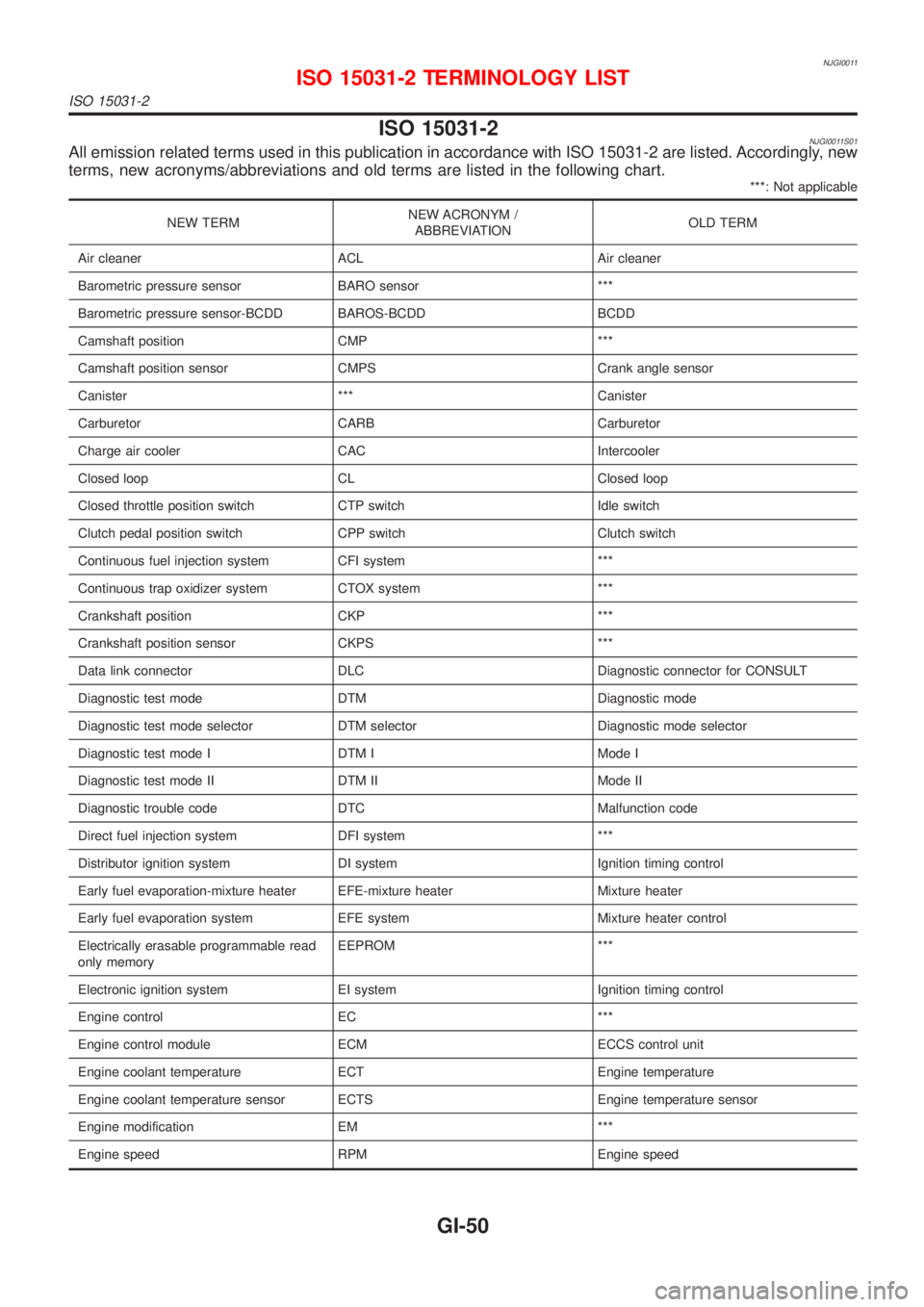
ISO 15031-2NJGI0011S01All emission related terms used in this publication in accordance with ISO 15031-2 are listed. Accordingly, new
terms, new acronyms/abbreviations and old terms are listed in the following chart.
***: Not applicable
NEW TERMNEW ACRONYM /
ABBREVIATIONOLD TERM
Air cleaner ACL Air cleaner
Barometric pressure sensor BARO sensor ***
Barometric pressure sensor-BCDD BAROS-BCDD BCDD
Camshaft position CMP ***
Camshaft position sensor CMPS Crank angle sensor
Canister *** Canister
Carburetor CARB Carburetor
Charge air cooler CAC Intercooler
Closed loop CL Closed loop
Closed throttle position switch CTP switch Idle switch
Clutch pedal position switch CPP switch Clutch switch
Continuous fuel injection system CFI system ***
Continuous trap oxidizer system CTOX system ***
Crankshaft position CKP ***
Crankshaft position sensor CKPS ***
Data link connector DLC Diagnostic connector for CONSULT
Diagnostic test mode DTM Diagnostic mode
Diagnostic test mode selector DTM selector Diagnostic mode selector
Diagnostic test mode I DTM I Mode I
Diagnostic test mode II DTM II Mode II
Diagnostic trouble code DTC Malfunction code
Direct fuel injection system DFI system ***
Distributor ignition system DI system Ignition timing control
Early fuel evaporation-mixture heater EFE-mixture heater Mixture heater
Early fuel evaporation system EFE system Mixture heater control
Electrically erasable programmable read
only memoryEEPROM ***
Electronic ignition system EI system Ignition timing control
Engine control EC ***
Engine control module ECM ECCS control unit
Engine coolant temperature ECT Engine temperature
Engine coolant temperature sensor ECTS Engine temperature sensor
Engine modification EM ***
Engine speed RPM Engine speed
ISO 15031-2 TERMINOLOGY LIST
ISO 15031-2
GI-50
Page 53 of 2493
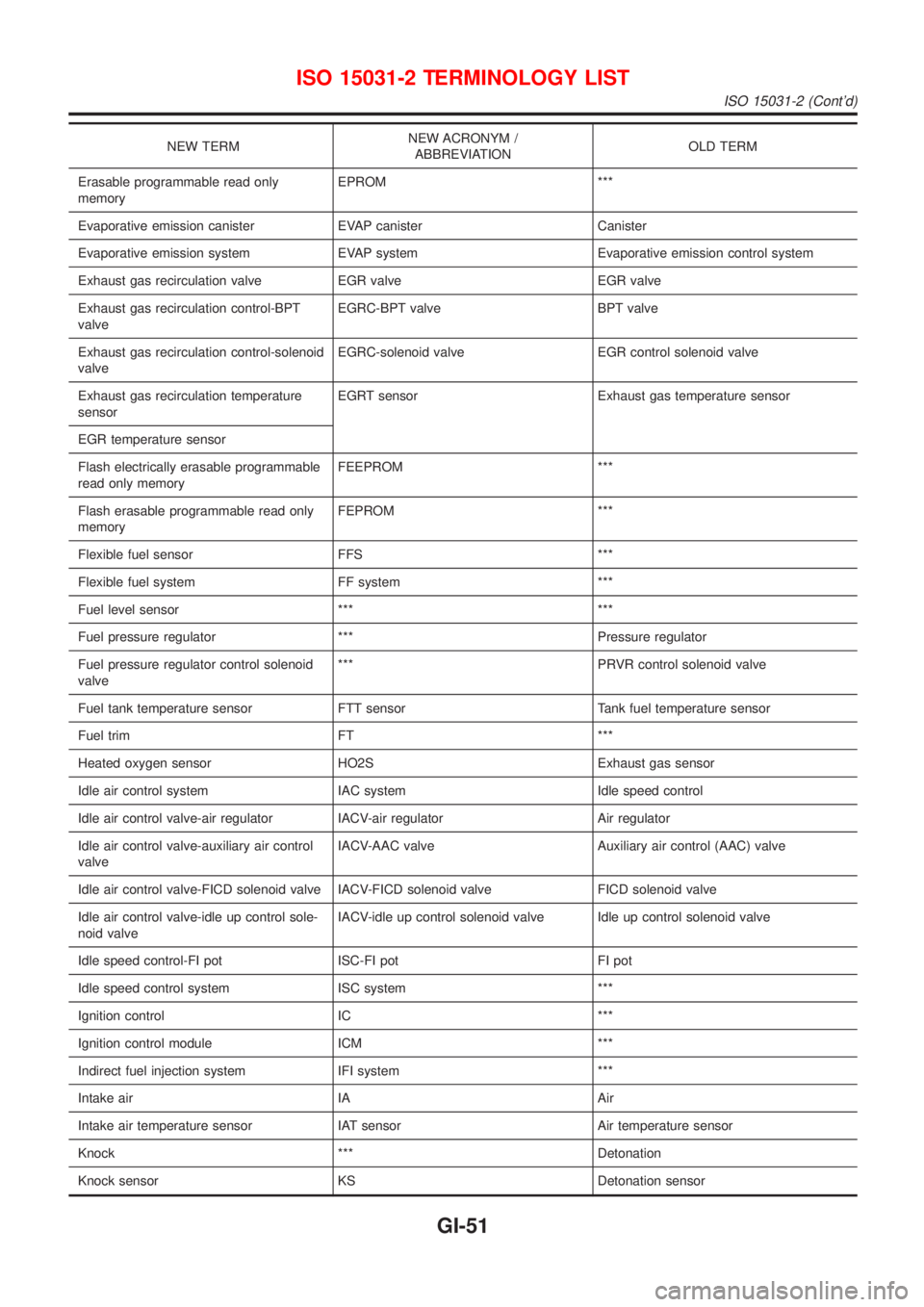
NEW TERMNEW ACRONYM /
ABBREVIATIONOLD TERM
Erasable programmable read only
memoryEPROM ***
Evaporative emission canister EVAP canister Canister
Evaporative emission system EVAP system Evaporative emission control system
Exhaust gas recirculation valve EGR valve EGR valve
Exhaust gas recirculation control-BPT
valveEGRC-BPT valve BPT valve
Exhaust gas recirculation control-solenoid
valveEGRC-solenoid valve EGR control solenoid valve
Exhaust gas recirculation temperature
sensorEGRT sensor Exhaust gas temperature sensor
EGR temperature sensor
Flash electrically erasable programmable
read only memoryFEEPROM ***
Flash erasable programmable read only
memoryFEPROM ***
Flexible fuel sensor FFS ***
Flexible fuel system FF system ***
Fuel level sensor *** ***
Fuel pressure regulator *** Pressure regulator
Fuel pressure regulator control solenoid
valve*** PRVR control solenoid valve
Fuel tank temperature sensor FTT sensor Tank fuel temperature sensor
Fuel trim FT ***
Heated oxygen sensor HO2S Exhaust gas sensor
Idle air control system IAC system Idle speed control
Idle air control valve-air regulator IACV-air regulator Air regulator
Idle air control valve-auxiliary air control
valveIACV-AAC valve Auxiliary air control (AAC) valve
Idle air control valve-FICD solenoid valve IACV-FICD solenoid valve FICD solenoid valve
Idle air control valve-idle up control sole-
noid valveIACV-idle up control solenoid valve Idle up control solenoid valve
Idle speed control-FI pot ISC-FI pot FI pot
Idle speed control system ISC system ***
Ignition control IC ***
Ignition control module ICM ***
Indirect fuel injection system IFI system ***
Intake air IA Air
Intake air temperature sensor IAT sensor Air temperature sensor
Knock *** Detonation
Knock sensor KS Detonation sensor
ISO 15031-2 TERMINOLOGY LIST
ISO 15031-2 (Cont'd)
GI-51
Page 55 of 2493
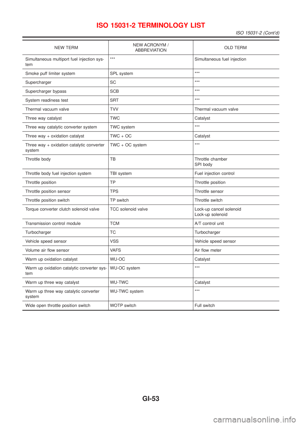
NEW TERMNEW ACRONYM /
ABBREVIATIONOLD TERM
Simultaneous multiport fuel injection sys-
tem*** Simultaneous fuel injection
Smoke puff limiter system SPL system ***
Supercharger SC ***
Supercharger bypass SCB ***
System readiness test SRT ***
Thermal vacuum valve TVV Thermal vacuum valve
Three way catalyst TWC Catalyst
Three way catalytic converter system TWC system ***
Three way + oxidation catalyst TWC + OC Catalyst
Three way + oxidation catalytic converter
systemTWC + OC system ***
Throttle body TB Throttle chamber
SPI body
Throttle body fuel injection system TBI system Fuel injection control
Throttle position TP Throttle position
Throttle position sensor TPS Throttle sensor
Throttle position switch TP switch Throttle switch
Torque converter clutch solenoid valve TCC solenoid valve Lock-up cancel solenoid
Lock-up solenoid
Transmission control module TCM A/T control unit
Turbocharger TC Turbocharger
Vehicle speed sensor VSS Vehicle speed sensor
Volume air flow sensor VAFS Air flow meter
Warm up oxidation catalyst WU-OC Catalyst
Warm up oxidation catalytic converter sys-
temWU-OC system ***
Warm up three way catalyst WU-TWC Catalyst
Warm up three way catalytic converter
systemWU-TWC system ***
Wide open throttle position switch WOTP switch Full switch
ISO 15031-2 TERMINOLOGY LIST
ISO 15031-2 (Cont'd)
GI-53
Page 68 of 2493
Maintenance Under Severe Driving Conditions
(Annual Driving Distance < 30,000 km/year)
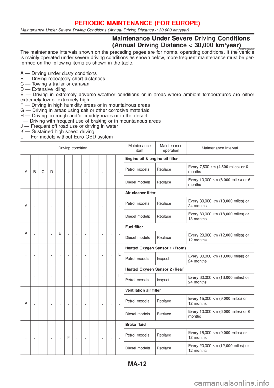
=NJMA0043S03The maintenance intervals shown on the preceding pages are for normal operating conditions. If the vehicle
is mainly operated under severe driving conditions as shown below, more frequent maintenance must be per-
formed on the following items as shown in the table.
A Ð Driving under dusty conditions
B Ð Driving repeatedly short distances
C Ð Towing a trailer or caravan
D Ð Extensive idling
E Ð Driving in extremely adverse weather conditions or in areas where ambient temperatures are either
extremely low or extremely high
F Ð Driving in high humidity areas or in mountainous areas
G Ð Driving in areas using salt or other corrosive materials
H Ð Driving on rough and/or muddy roads or in the desert
I Ð Driving with frequent use of braking or in mountainous areas
J Ð Frequent off road use or driving in water
K Ð Sustained high speed driving
L Ð For models without Euro-OBD system
Driving conditionMaintenance
itemMaintenance
operationMaintenance interval
ABCD........Engine oil & engine oil filter
Petrol models ReplaceEvery 7,500 km (4,500 miles) or 6
months
Diesel models ReplaceEvery 10,000 km (6,000 miles) or 6
months
A...........Air cleaner filter
Petrol models ReplaceEvery 30,000 km (18,000 miles) or
24 months
Diesel models ReplaceEvery 30,000 km (18,000 miles) or
18 months
A...E.......Fuel filter
Diesel models ReplaceEvery 20,000 km (12,000 miles) or
12 months
...........LHeated Oxygen Sensor 1 (Front)
Petrol models InspectEvery 30,000 km (18,000 miles) or
24 months
...........LHeated Oxygen Sensor 2 (Rear)
Petrol models InspectEvery 30,000 km (18,000 miles) or
24 months
A...........Ventilation air filter
Petrol models ReplaceEvery 15,000 km (9,000 miles) or
12 months
Diesel models ReplaceEvery 10,000 km (6,000 miles) or 6
months
.....F......Brake fluid
Petrol models ReplaceEvery 15,000 km (9,000 miles) or
12 months
Diesel models ReplaceEvery 20,000 km (12,000 miles) or
12 months
PERIODIC MAINTENANCE (FOR EUROPE)
Maintenance Under Severe Driving Conditions (Annual Driving Distance < 30,000 km/year)
MA-12
Page 74 of 2493
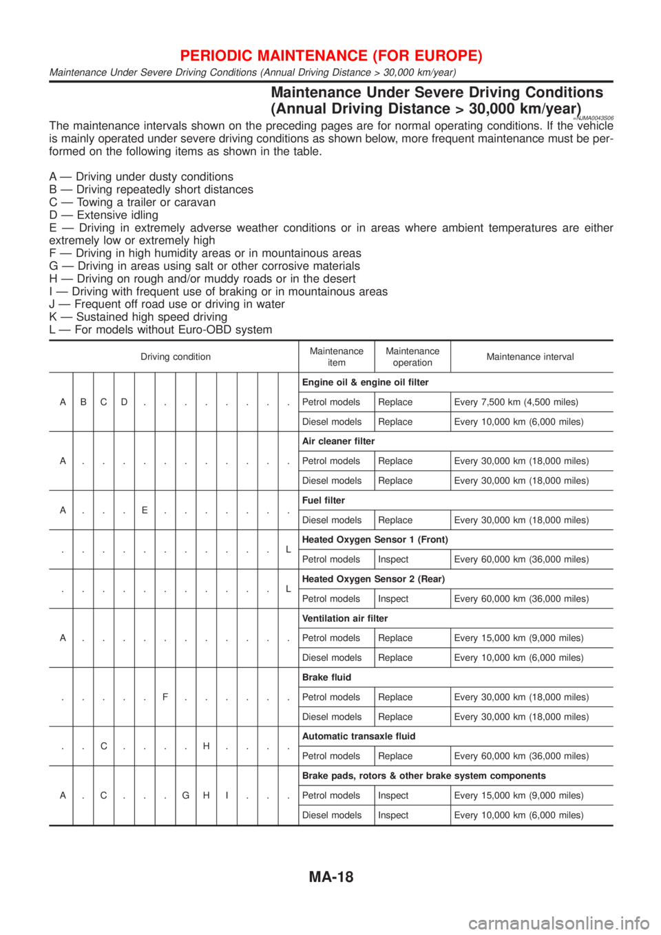
Maintenance Under Severe Driving Conditions
(Annual Driving Distance > 30,000 km/year)
=NJMA0043S06The maintenance intervals shown on the preceding pages are for normal operating conditions. If the vehicle
is mainly operated under severe driving conditions as shown below, more frequent maintenance must be per-
formed on the following items as shown in the table.
A Ð Driving under dusty conditions
B Ð Driving repeatedly short distances
C Ð Towing a trailer or caravan
D Ð Extensive idling
E Ð Driving in extremely adverse weather conditions or in areas where ambient temperatures are either
extremely low or extremely high
F Ð Driving in high humidity areas or in mountainous areas
G Ð Driving in areas using salt or other corrosive materials
H Ð Driving on rough and/or muddy roads or in the desert
I Ð Driving with frequent use of braking or in mountainous areas
J Ð Frequent off road use or driving in water
K Ð Sustained high speed driving
L Ð For models without Euro-OBD system
Driving conditionMaintenance
itemMaintenance
operationMaintenance interval
ABCD........Engine oil & engine oil filter
Petrol models Replace Every 7,500 km (4,500 miles)
Diesel models Replace Every 10,000 km (6,000 miles)
A...........Air cleaner filter
Petrol models Replace Every 30,000 km (18,000 miles)
Diesel models Replace Every 30,000 km (18,000 miles)
A...E.......Fuel filter
Diesel models Replace Every 30,000 km (18,000 miles)
...........LHeated Oxygen Sensor 1 (Front)
Petrol models Inspect Every 60,000 km (36,000 miles)
...........LHeated Oxygen Sensor 2 (Rear)
Petrol models Inspect Every 60,000 km (36,000 miles)
A...........Ventilation air filter
Petrol models Replace Every 15,000 km (9,000 miles)
Diesel models Replace Every 10,000 km (6,000 miles)
.....F......Brake fluid
Petrol models Replace Every 30,000 km (18,000 miles)
Diesel models Replace Every 30,000 km (18,000 miles)
..C....H....Automatic transaxle fluid
Petrol models Replace Every 60,000 km (36,000 miles)
A.C...GHI...Brake pads, rotors & other brake system components
Petrol models Inspect Every 15,000 km (9,000 miles)
Diesel models Inspect Every 10,000 km (6,000 miles)
PERIODIC MAINTENANCE (FOR EUROPE)
Maintenance Under Severe Driving Conditions (Annual Driving Distance > 30,000 km/year)
MA-18
Page 297 of 2493
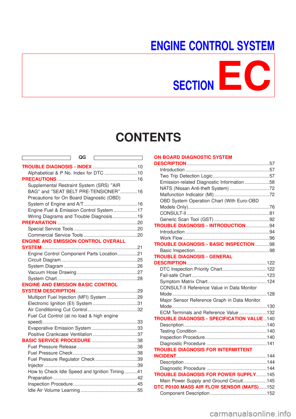
ENGINE CONTROL SYSTEM
SECTION
EC
CONTENTS
QG
TROUBLE DIAGNOSIS - INDEX..................................10
Alphabetical & P No. Index for DTC .........................10
PRECAUTIONS.............................................................16
Supplemental Restraint System (SRS)²AIR
BAG²and²SEAT BELT PRE-TENSIONER².............16
Precautions for On Board Diagnostic (OBD)
System of Engine and A/T.........................................16
Engine Fuel & Emission Control System ..................17
Wiring Diagrams and Trouble Diagnosis ...................19
PREPARATION.............................................................20
Special Service Tools ................................................20
Commercial Service Tools .........................................20
ENGINE AND EMISSION CONTROL OVERALL
SYSTEM.........................................................................21
Engine Control Component Parts Location ...............21
Circuit Diagram ..........................................................25
System Diagram ........................................................26
Vacuum Hose Drawing ..............................................27
System Chart .............................................................28
ENGINE AND EMISSION BASIC CONTROL
SYSTEM DESCRIPTION...............................................29
Multiport Fuel Injection (MFI) System .......................29
Electronic Ignition (EI) System ..................................31
Air Conditioning Cut Control ......................................32
Fuel Cut Control (at no load & high engine
speed) ........................................................................33
Evaporative Emission System ...................................33
Positive Crankcase Ventilation ..................................37
BASIC SERVICE PROCEDURE...................................38
Fuel Pressure Release ..............................................38
Fuel Pressure Check .................................................38
Fuel Pressure Regulator Check ................................39
Injector .......................................................................39
How to Check Idle Speed and Ignition Timing ..........41
Preparation ................................................................42
Inspection Procedure .................................................45
Idle Air Volume Learning ...........................................55ON BOARD DIAGNOSTIC SYSTEM
DESCRIPTION...............................................................57
Introduction ................................................................57
Two Trip Detection Logic ...........................................57
Emission-related Diagnostic Information ...................58
NATS (Nissan Anti-theft System) ..............................72
Malfunction Indicator (MI) ..........................................72
OBD System Operation Chart (With Euro-OBD
Models Only)..............................................................76
CONSULT-II ...............................................................81
Generic Scan Tool (GST) ..........................................92
TROUBLE DIAGNOSIS - INTRODUCTION..................94
Introduction ................................................................94
Work Flow ..................................................................96
TROUBLE DIAGNOSIS - BASIC INSPECTION...........98
Basic Inspection.........................................................98
TROUBLE DIAGNOSIS - GENERAL
DESCRIPTION.............................................................122
DTC Inspection Priority Chart..................................122
Fail-safe Chart .........................................................123
Symptom Matrix Chart .............................................124
CONSULT-II Reference Value in Data Monitor
Mode ........................................................................128
Major Sensor Reference Graph in Data Monitor
Mode ........................................................................130
ECM Terminals and Reference Value .....................132
TROUBLE DIAGNOSIS - SPECIFICATION VALUE..140
Description ...............................................................140
Testing Condition .....................................................140
Inspection Procedure ...............................................140
Diagnostic Procedure ..............................................141
TROUBLE DIAGNOSIS FOR INTERMITTENT
INCIDENT.....................................................................144
Description ...............................................................144
Diagnostic Procedure ..............................................144
TROUBLE DIAGNOSIS FOR POWER SUPPLY........145
Main Power Supply and Ground Circuit ..................145
DTC P0100 MASS AIR FLOW SENSOR (MAFS)......152
Component Description ...........................................152
Page 300 of 2493
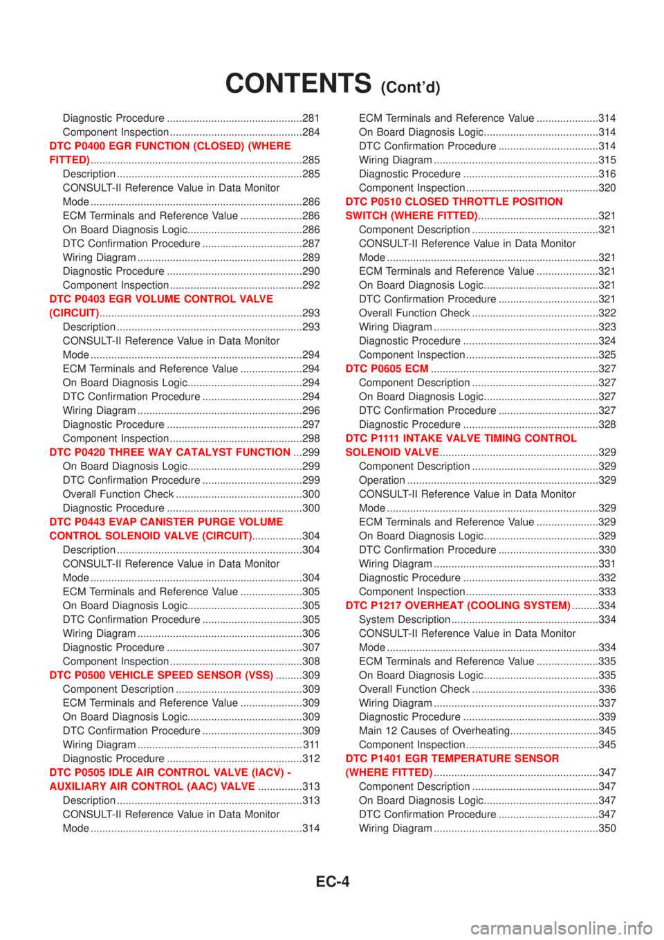
Diagnostic Procedure ..............................................281
Component Inspection .............................................284
DTC P0400 EGR FUNCTION (CLOSED) (WHERE
FITTED)........................................................................285
Description ...............................................................285
CONSULT-II Reference Value in Data Monitor
Mode ........................................................................286
ECM Terminals and Reference Value .....................286
On Board Diagnosis Logic.......................................286
DTC Confirmation Procedure ..................................287
Wiring Diagram ........................................................289
Diagnostic Procedure ..............................................290
Component Inspection .............................................292
DTC P0403 EGR VOLUME CONTROL VALVE
(CIRCUIT).....................................................................293
Description ...............................................................293
CONSULT-II Reference Value in Data Monitor
Mode ........................................................................294
ECM Terminals and Reference Value .....................294
On Board Diagnosis Logic.......................................294
DTC Confirmation Procedure ..................................294
Wiring Diagram ........................................................296
Diagnostic Procedure ..............................................297
Component Inspection .............................................298
DTC P0420 THREE WAY CATALYST FUNCTION...299
On Board Diagnosis Logic.......................................299
DTC Confirmation Procedure ..................................299
Overall Function Check ...........................................300
Diagnostic Procedure ..............................................300
DTC P0443 EVAP CANISTER PURGE VOLUME
CONTROL SOLENOID VALVE (CIRCUIT).................304
Description ...............................................................304
CONSULT-II Reference Value in Data Monitor
Mode ........................................................................304
ECM Terminals and Reference Value .....................305
On Board Diagnosis Logic.......................................305
DTC Confirmation Procedure ..................................305
Wiring Diagram ........................................................306
Diagnostic Procedure ..............................................307
Component Inspection .............................................308
DTC P0500 VEHICLE SPEED SENSOR (VSS).........309
Component Description ...........................................309
ECM Terminals and Reference Value .....................309
On Board Diagnosis Logic.......................................309
DTC Confirmation Procedure ..................................309
Wiring Diagram ........................................................ 311
Diagnostic Procedure ..............................................312
DTC P0505 IDLE AIR CONTROL VALVE (IACV) -
AUXILIARY AIR CONTROL (AAC) VALVE...............313
Description ...............................................................313
CONSULT-II Reference Value in Data Monitor
Mode ........................................................................314ECM Terminals and Reference Value .....................314
On Board Diagnosis Logic.......................................314
DTC Confirmation Procedure ..................................314
Wiring Diagram ........................................................315
Diagnostic Procedure ..............................................316
Component Inspection .............................................320
DTC P0510 CLOSED THROTTLE POSITION
SWITCH (WHERE FITTED).........................................321
Component Description ...........................................321
CONSULT-II Reference Value in Data Monitor
Mode ........................................................................321
ECM Terminals and Reference Value .....................321
On Board Diagnosis Logic.......................................321
DTC Confirmation Procedure ..................................321
Overall Function Check ...........................................322
Wiring Diagram ........................................................323
Diagnostic Procedure ..............................................324
Component Inspection .............................................325
DTC P0605 ECM.........................................................327
Component Description ...........................................327
On Board Diagnosis Logic.......................................327
DTC Confirmation Procedure ..................................327
Diagnostic Procedure ..............................................328
D T C P 1111INTAKE VALVE TIMING CONTROL
SOLENOID VALVE......................................................329
Component Description ...........................................329
Operation .................................................................329
CONSULT-II Reference Value in Data Monitor
Mode ........................................................................329
ECM Terminals and Reference Value .....................329
On Board Diagnosis Logic.......................................329
DTC Confirmation Procedure ..................................330
Wiring Diagram ........................................................331
Diagnostic Procedure ..............................................332
Component Inspection .............................................333
DTC P1217 OVERHEAT (COOLING SYSTEM).........334
System Description ..................................................334
CONSULT-II Reference Value in Data Monitor
Mode ........................................................................334
ECM Terminals and Reference Value .....................335
On Board Diagnosis Logic.......................................335
Overall Function Check ...........................................336
Wiring Diagram ........................................................337
Diagnostic Procedure ..............................................339
Main 12 Causes of Overheating..............................345
Component Inspection .............................................345
DTC P1401 EGR TEMPERATURE SENSOR
(WHERE FITTED)........................................................347
Component Description ...........................................347
On Board Diagnosis Logic.......................................347
DTC Confirmation Procedure ..................................347
Wiring Diagram ........................................................350
CONTENTS(Cont'd)
EC-4
Page 302 of 2493
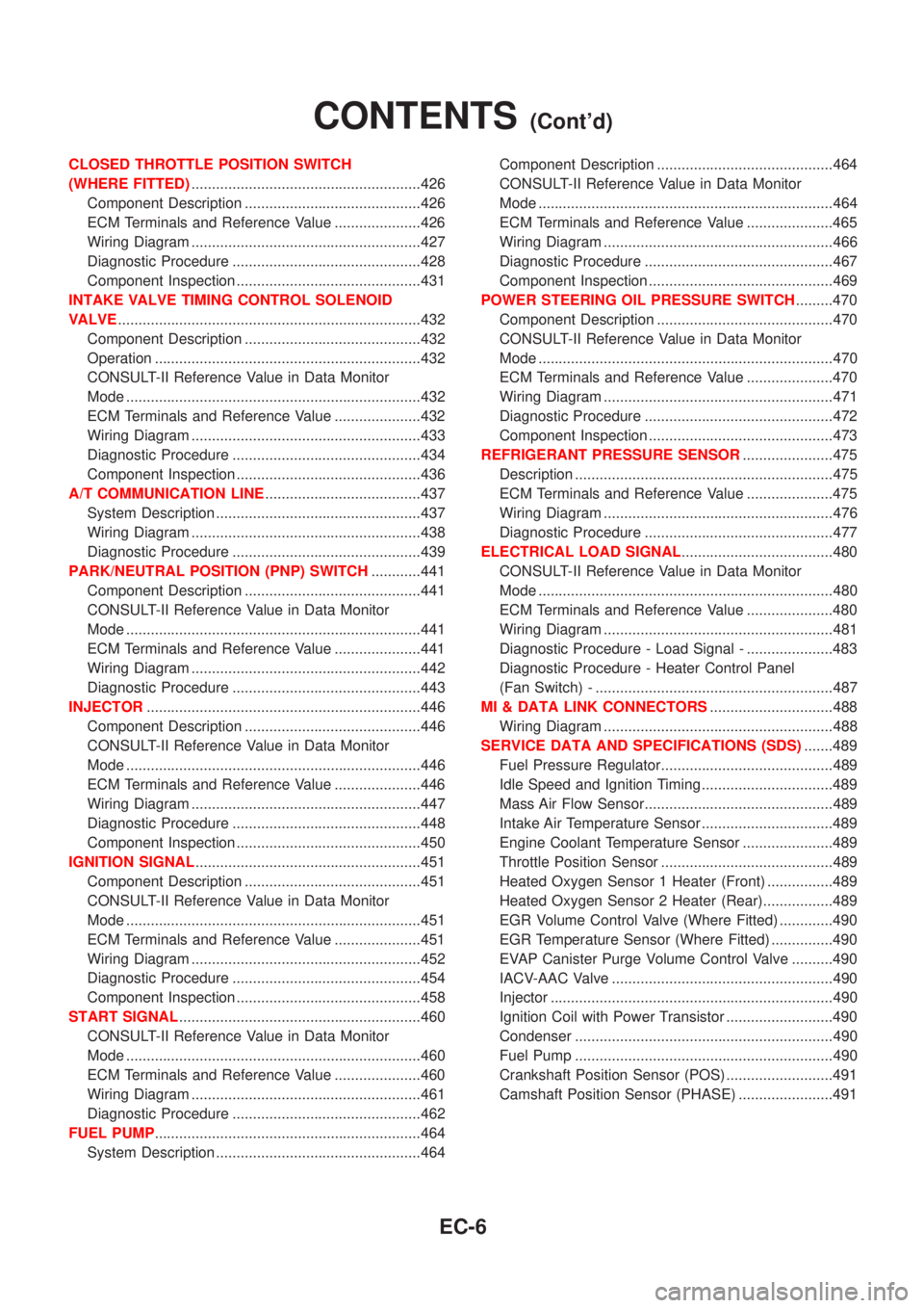
CLOSED THROTTLE POSITION SWITCH
(WHERE FITTED)........................................................426
Component Description ...........................................426
ECM Terminals and Reference Value .....................426
Wiring Diagram ........................................................427
Diagnostic Procedure ..............................................428
Component Inspection .............................................431
INTAKE VALVE TIMING CONTROL SOLENOID
VALVE..........................................................................432
Component Description ...........................................432
Operation .................................................................432
CONSULT-II Reference Value in Data Monitor
Mode ........................................................................432
ECM Terminals and Reference Value .....................432
Wiring Diagram ........................................................433
Diagnostic Procedure ..............................................434
Component Inspection .............................................436
A/T COMMUNICATION LINE......................................437
System Description ..................................................437
Wiring Diagram ........................................................438
Diagnostic Procedure ..............................................439
PARK/NEUTRAL POSITION (PNP) SWITCH............441
Component Description ...........................................441
CONSULT-II Reference Value in Data Monitor
Mode ........................................................................441
ECM Terminals and Reference Value .....................441
Wiring Diagram ........................................................442
Diagnostic Procedure ..............................................443
INJECTOR...................................................................446
Component Description ...........................................446
CONSULT-II Reference Value in Data Monitor
Mode ........................................................................446
ECM Terminals and Reference Value .....................446
Wiring Diagram ........................................................447
Diagnostic Procedure ..............................................448
Component Inspection .............................................450
IGNITION SIGNAL.......................................................451
Component Description ...........................................451
CONSULT-II Reference Value in Data Monitor
Mode ........................................................................451
ECM Terminals and Reference Value .....................451
Wiring Diagram ........................................................452
Diagnostic Procedure ..............................................454
Component Inspection .............................................458
START SIGNAL...........................................................460
CONSULT-II Reference Value in Data Monitor
Mode ........................................................................460
ECM Terminals and Reference Value .....................460
Wiring Diagram ........................................................461
Diagnostic Procedure ..............................................462
FUEL PUMP.................................................................464
System Description ..................................................464Component Description ...........................................464
CONSULT-II Reference Value in Data Monitor
Mode ........................................................................464
ECM Terminals and Reference Value .....................465
Wiring Diagram ........................................................466
Diagnostic Procedure ..............................................467
Component Inspection .............................................469
POWER STEERING OIL PRESSURE SWITCH.........470
Component Description ...........................................470
CONSULT-II Reference Value in Data Monitor
Mode ........................................................................470
ECM Terminals and Reference Value .....................470
Wiring Diagram ........................................................471
Diagnostic Procedure ..............................................472
Component Inspection .............................................473
REFRIGERANT PRESSURE SENSOR......................475
Description ...............................................................475
ECM Terminals and Reference Value .....................475
Wiring Diagram ........................................................476
Diagnostic Procedure ..............................................477
ELECTRICAL LOAD SIGNAL.....................................480
CONSULT-II Reference Value in Data Monitor
Mode ........................................................................480
ECM Terminals and Reference Value .....................480
Wiring Diagram ........................................................481
Diagnostic Procedure - Load Signal - .....................483
Diagnostic Procedure - Heater Control Panel
(Fan Switch) - ..........................................................487
MI & DATA LINK CONNECTORS..............................488
Wiring Diagram ........................................................488
SERVICE DATA AND SPECIFICATIONS (SDS).......489
Fuel Pressure Regulator..........................................489
Idle Speed and Ignition Timing ................................489
Mass Air Flow Sensor..............................................489
Intake Air Temperature Sensor ................................489
Engine Coolant Temperature Sensor ......................489
Throttle Position Sensor ..........................................489
Heated Oxygen Sensor 1 Heater (Front) ................489
Heated Oxygen Sensor 2 Heater (Rear).................489
EGR Volume Control Valve (Where Fitted) .............490
EGR Temperature Sensor (Where Fitted) ...............490
EVAP Canister Purge Volume Control Valve ..........490
IACV-AAC Valve ......................................................490
Injector .....................................................................490
Ignition Coil with Power Transistor ..........................490
Condenser ...............................................................490
Fuel Pump ...............................................................490
Crankshaft Position Sensor (POS) ..........................491
Camshaft Position Sensor (PHASE) .......................491
CONTENTS(Cont'd)
EC-6
Page 303 of 2493
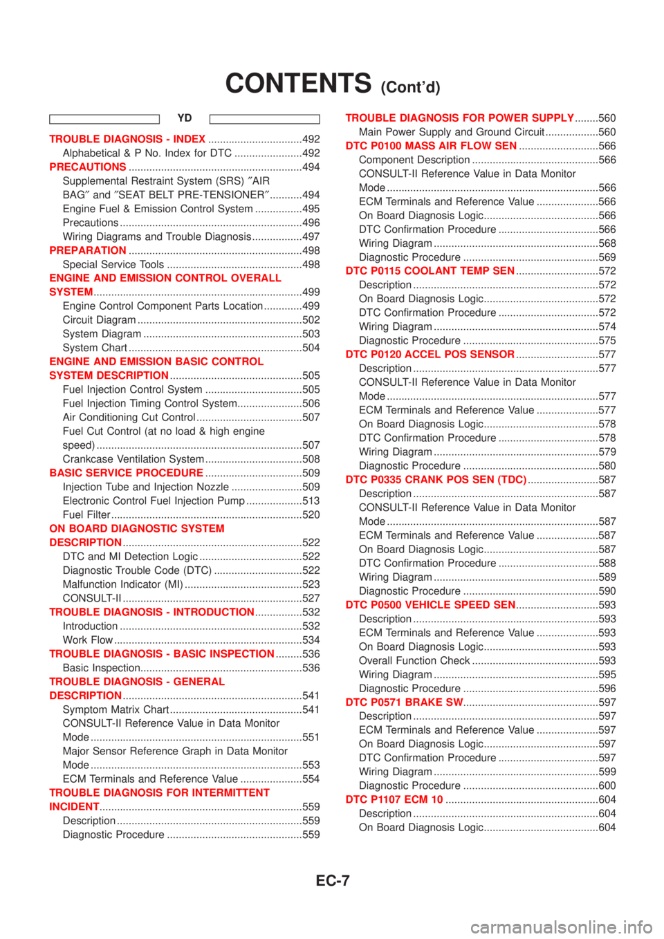
YD
TROUBLE DIAGNOSIS - INDEX................................492
Alphabetical & P No. Index for DTC .......................492
PRECAUTIONS...........................................................494
Supplemental Restraint System (SRS)²AIR
BAG²and²SEAT BELT PRE-TENSIONER²...........494
Engine Fuel & Emission Control System ................495
Precautions ..............................................................496
Wiring Diagrams and Trouble Diagnosis .................497
PREPARATION...........................................................498
Special Service Tools ..............................................498
ENGINE AND EMISSION CONTROL OVERALL
SYSTEM.......................................................................499
Engine Control Component Parts Location .............499
Circuit Diagram ........................................................502
System Diagram ......................................................503
System Chart ...........................................................504
ENGINE AND EMISSION BASIC CONTROL
SYSTEM DESCRIPTION.............................................505
Fuel Injection Control System .................................505
Fuel Injection Timing Control System......................506
Air Conditioning Cut Control ....................................507
Fuel Cut Control (at no load & high engine
speed) ......................................................................507
Crankcase Ventilation System .................................508
BASIC SERVICE PROCEDURE.................................509
Injection Tube and Injection Nozzle ........................509
Electronic Control Fuel Injection Pump ...................513
Fuel Filter .................................................................520
ON BOARD DIAGNOSTIC SYSTEM
DESCRIPTION.............................................................522
DTC and MI Detection Logic ...................................522
Diagnostic Trouble Code (DTC) ..............................522
Malfunction Indicator (MI) ........................................523
CONSULT-II .............................................................527
TROUBLE DIAGNOSIS - INTRODUCTION................532
Introduction ..............................................................532
Work Flow ................................................................534
TROUBLE DIAGNOSIS - BASIC INSPECTION.........536
Basic Inspection.......................................................536
TROUBLE DIAGNOSIS - GENERAL
DESCRIPTION.............................................................541
Symptom Matrix Chart .............................................541
CONSULT-II Reference Value in Data Monitor
Mode ........................................................................551
Major Sensor Reference Graph in Data Monitor
Mode ........................................................................553
ECM Terminals and Reference Value .....................554
TROUBLE DIAGNOSIS FOR INTERMITTENT
INCIDENT.....................................................................559
Description ...............................................................559
Diagnostic Procedure ..............................................559TROUBLE DIAGNOSIS FOR POWER SUPPLY........560
Main Power Supply and Ground Circuit ..................560
DTC P0100 MASS AIR FLOW SEN...........................566
Component Description ...........................................566
CONSULT-II Reference Value in Data Monitor
Mode ........................................................................566
ECM Terminals and Reference Value .....................566
On Board Diagnosis Logic.......................................566
DTC Confirmation Procedure ..................................566
Wiring Diagram ........................................................568
Diagnostic Procedure ..............................................569
DTC P0115 COOLANT TEMP SEN............................572
Description ...............................................................572
On Board Diagnosis Logic.......................................572
DTC Confirmation Procedure ..................................572
Wiring Diagram ........................................................574
Diagnostic Procedure ..............................................575
DTC P0120 ACCEL POS SENSOR............................577
Description ...............................................................577
CONSULT-II Reference Value in Data Monitor
Mode ........................................................................577
ECM Terminals and Reference Value .....................577
On Board Diagnosis Logic.......................................578
DTC Confirmation Procedure ..................................578
Wiring Diagram ........................................................579
Diagnostic Procedure ..............................................580
DTC P0335 CRANK POS SEN (TDC)........................587
Description ...............................................................587
CONSULT-II Reference Value in Data Monitor
Mode ........................................................................587
ECM Terminals and Reference Value .....................587
On Board Diagnosis Logic.......................................587
DTC Confirmation Procedure ..................................588
Wiring Diagram ........................................................589
Diagnostic Procedure ..............................................590
DTC P0500 VEHICLE SPEED SEN............................593
Description ...............................................................593
ECM Terminals and Reference Value .....................593
On Board Diagnosis Logic.......................................593
Overall Function Check ...........................................593
Wiring Diagram ........................................................595
Diagnostic Procedure ..............................................596
DTC P0571 BRAKE SW..............................................597
Description ...............................................................597
ECM Terminals and Reference Value .....................597
On Board Diagnosis Logic.......................................597
DTC Confirmation Procedure ..................................597
Wiring Diagram ........................................................599
Diagnostic Procedure ..............................................600
DTC P1107 ECM 10....................................................604
Description ...............................................................604
On Board Diagnosis Logic.......................................604
CONTENTS(Cont'd)
EC-7
Page 307 of 2493
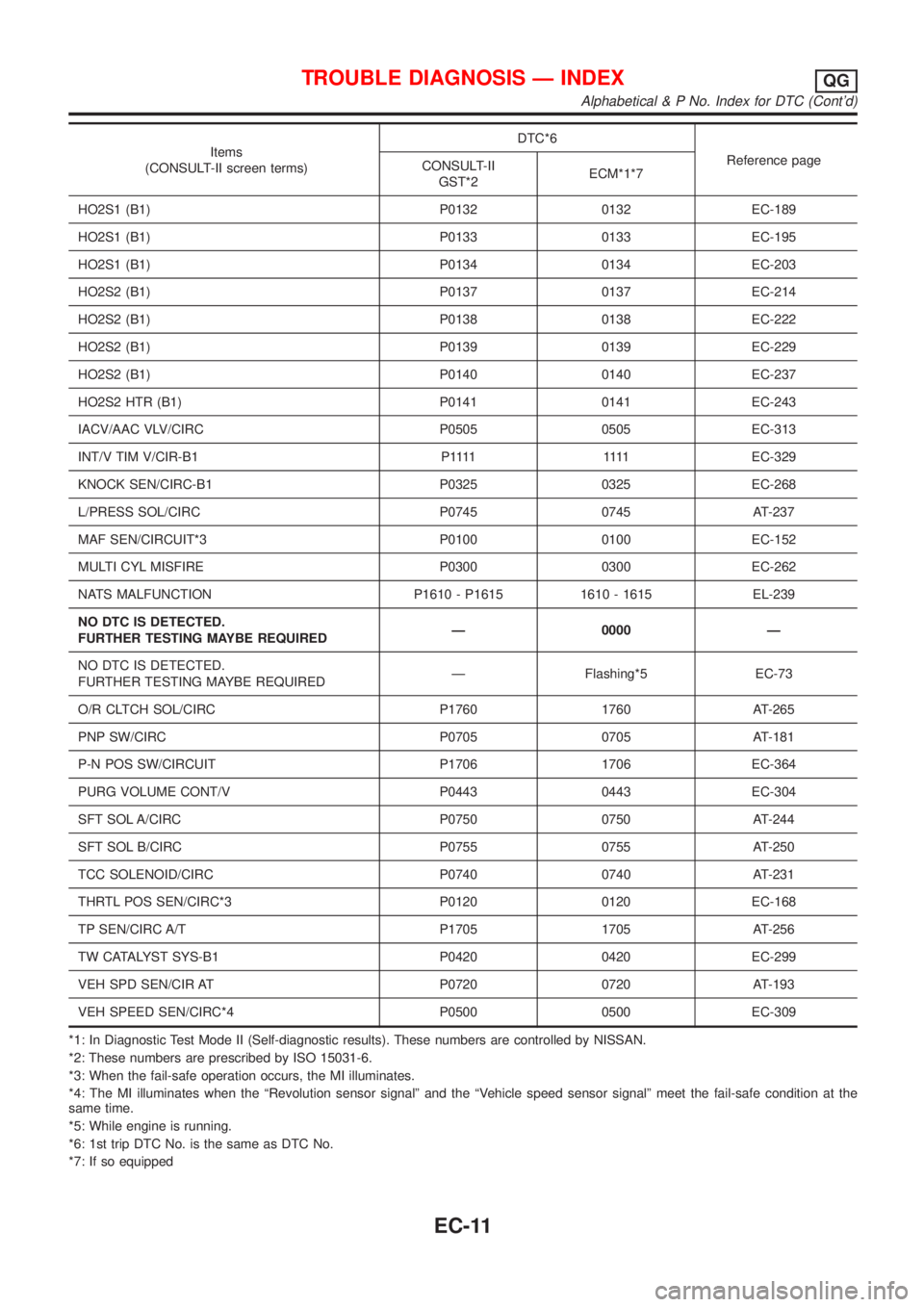
Items
(CONSULT-II screen terms)DTC*6
Reference page
CONSULT-II
GST*2ECM*1*7
HO2S1 (B1) P0132 0132 EC-189
HO2S1 (B1) P0133 0133 EC-195
HO2S1 (B1) P0134 0134 EC-203
HO2S2 (B1) P0137 0137 EC-214
HO2S2 (B1) P0138 0138 EC-222
HO2S2 (B1) P0139 0139 EC-229
HO2S2 (B1) P0140 0140 EC-237
HO2S2 HTR (B1) P0141 0141 EC-243
IACV/AAC VLV/CIRC P0505 0505 EC-313
INT/V TIM V/CIR-B1 P1111 1111EC-329
KNOCK SEN/CIRC-B1 P0325 0325 EC-268
L/PRESS SOL/CIRC P0745 0745 AT-237
MAF SEN/CIRCUIT*3 P0100 0100 EC-152
MULTI CYL MISFIRE P0300 0300 EC-262
NATS MALFUNCTION P1610 - P1615 1610 - 1615 EL-239
NO DTC IS DETECTED.
FURTHER TESTING MAYBE REQUIREDÐ 0000 Ð
NO DTC IS DETECTED.
FURTHER TESTING MAYBE REQUIREDÐ Flashing*5 EC-73
O/R CLTCH SOL/CIRC P1760 1760 AT-265
PNP SW/CIRC P0705 0705 AT-181
P-N POS SW/CIRCUIT P1706 1706 EC-364
PURG VOLUME CONT/V P0443 0443 EC-304
SFT SOL A/CIRC P0750 0750 AT-244
SFT SOL B/CIRC P0755 0755 AT-250
TCC SOLENOID/CIRC P0740 0740 AT-231
THRTL POS SEN/CIRC*3 P0120 0120 EC-168
TP SEN/CIRC A/T P1705 1705 AT-256
TW CATALYST SYS-B1 P0420 0420 EC-299
VEH SPD SEN/CIR AT P0720 0720 AT-193
VEH SPEED SEN/CIRC*4 P0500 0500 EC-309
*1: In Diagnostic Test Mode II (Self-diagnostic results). These numbers are controlled by NISSAN.
*2: These numbers are prescribed by ISO 15031-6.
*3: When the fail-safe operation occurs, the MI illuminates.
*4: The MI illuminates when the ªRevolution sensor signalº and the ªVehicle speed sensor signalº meet the fail-safe condition at the
same time.
*5: While engine is running.
*6: 1st trip DTC No. is the same as DTC No.
*7: If so equipped
TROUBLE DIAGNOSIS Ð INDEXQG
Alphabetical & P No. Index for DTC (Cont'd)
EC-11