steering wheel adjustment NISSAN ALMERA N16 2001 Electronic Repair Manual
[x] Cancel search | Manufacturer: NISSAN, Model Year: 2001, Model line: ALMERA N16, Model: NISSAN ALMERA N16 2001Pages: 2493, PDF Size: 66.97 MB
Page 13 of 2493

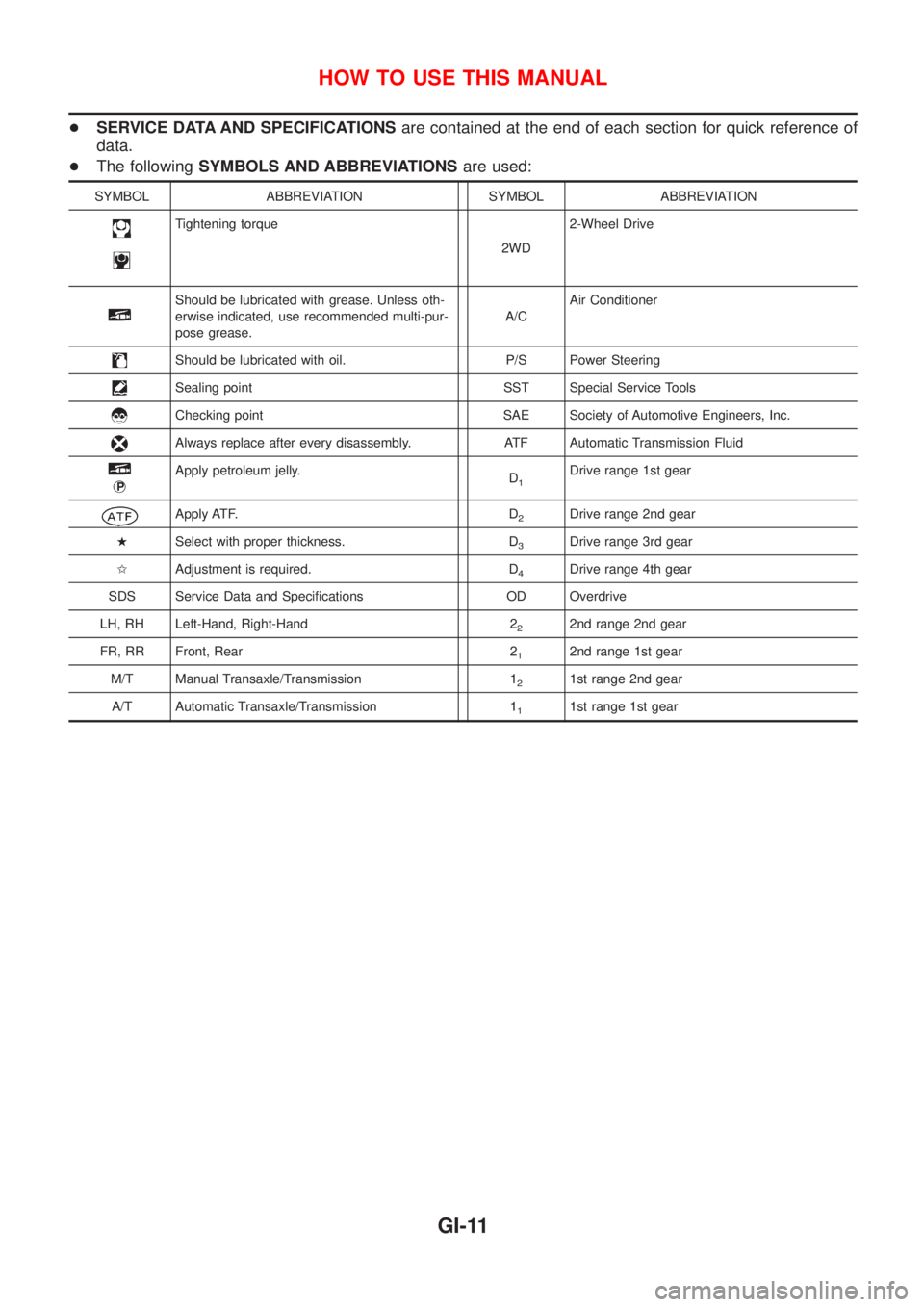
+SERVICE DATA AND SPECIFICATIONSare contained at the end of each section for quick reference of
data.
+The followingSYMBOLS AND ABBREVIATIONSare used:
SYMBOL ABBREVIATION SYMBOL ABBREVIATION
Tightening torque
2WD2-Wheel Drive
Should be lubricated with grease. Unless oth-
erwise indicated, use recommended multi-pur-
pose grease.A/CAir Conditioner
Should be lubricated with oil. P/S Power Steering
Sealing point SST Special Service Tools
Checking point SAE Society of Automotive Engineers, Inc.
Always replace after every disassembly. ATF Automatic Transmission Fluid
jP
Apply petroleum jelly.
D1Drive range 1st gear
Apply ATF. D2Drive range 2nd gear
HSelect with proper thickness. D
3Drive range 3rd gear
IAdjustment is required. D
4Drive range 4th gear
SDS Service Data and Specifications OD Overdrive
LH, RH Left-Hand, Right-Hand 2
22nd range 2nd gear
FR, RR Front, Rear 2
12nd range 1st gear
M/T Manual Transaxle/Transmission 1
21st range 2nd gear
A/T Automatic Transaxle/Transmission 1
11st range 1st gear
HOW TO USE THIS MANUAL
GI-11
Page 1035 of 2493

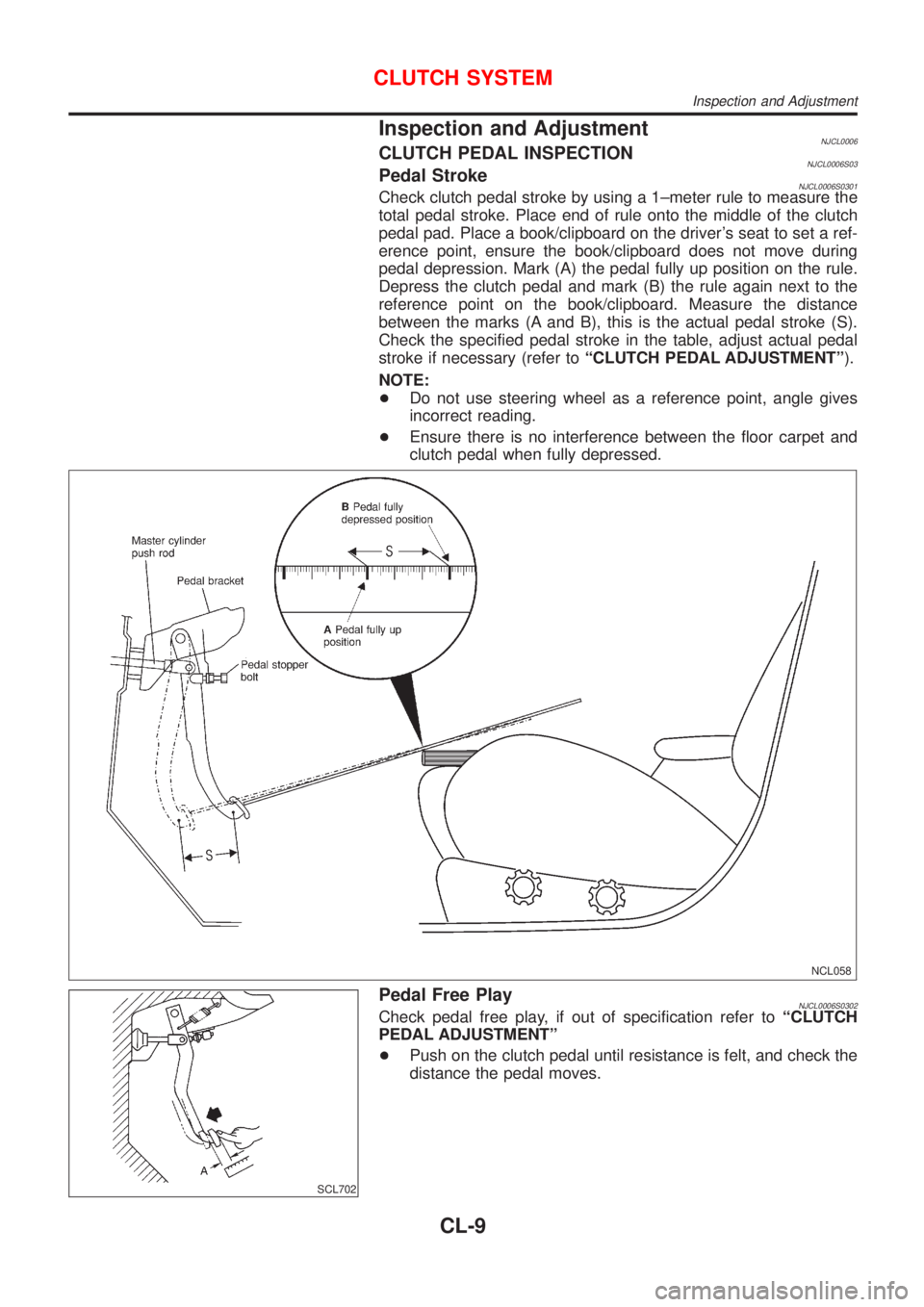
Inspection and AdjustmentNJCL0006CLUTCH PEDAL INSPECTIONNJCL0006S03Pedal StrokeNJCL0006S0301Check clutch pedal stroke by using a 1±meter rule to measure the
total pedal stroke. Place end of rule onto the middle of the clutch
pedal pad. Place a book/clipboard on the driver's seat to set a ref-
erence point, ensure the book/clipboard does not move during
pedal depression. Mark (A) the pedal fully up position on the rule.
Depress the clutch pedal and mark (B) the rule again next to the
reference point on the book/clipboard. Measure the distance
between the marks (A and B), this is the actual pedal stroke (S).
Check the specified pedal stroke in the table, adjust actual pedal
stroke if necessary (refer toªCLUTCH PEDAL ADJUSTMENTº).
NOTE:
+Do not use steering wheel as a reference point, angle gives
incorrect reading.
+Ensure there is no interference between the floor carpet and
clutch pedal when fully depressed.
NCL058
SCL702
Pedal Free PlayNJCL0006S0302Check pedal free play, if out of specification refer toªCLUTCH
PEDAL ADJUSTMENTº
+Push on the clutch pedal until resistance is felt, and check the
distance the pedal moves.
CLUTCH SYSTEM
Inspection and Adjustment
CL-9
Page 1791 of 2493

STEERING SYSTEM
SECTION
ST
CONTENTS
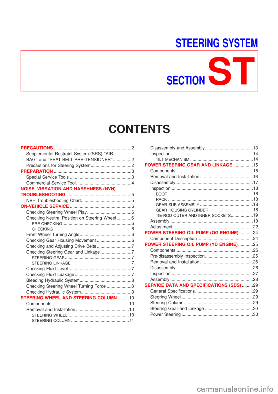
PRECAUTIONS...............................................................2
Supplemental Restraint System (SRS)²AIR
BAG²and²SEAT BELT PRE-TENSIONER²...............2
Precautions for Steering System .................................2
PREPARATION...............................................................3
Special Service Tools ..................................................3
Commercial Service Tool .............................................4
NOISE, VIBRATION AND HARSHNESS (NVH)
TROUBLESHOOTING.....................................................5
NVH Troubleshooting Chart.........................................5
ON-VEHICLE SERVICE..................................................6
Checking Steering Wheel Play ....................................6
Checking Neutral Position on Steering Wheel ............6
PRE-CHECKING........................................................6
CHECKING...............................................................6
Front Wheel Turning Angle ..........................................6
Checking Gear Housing Movement ............................6
Checking and Adjusting Drive Belts ............................7
Checking Steering Gear and Linkage .........................7
STEERING GEAR......................................................7
STEERING LINKAGE.................................................7
Checking Fluid Level ...................................................7
Checking Fluid Leakage ..............................................7
Bleeding Hydraulic System..........................................8
Checking Steering Wheel Turning Force ....................8
Checking Hydraulic System.........................................9
STEERING WHEEL AND STEERING COLUMN.........10
Components...............................................................10
Removal and Installation ...........................................10
STEERING WHEEL.................................................10
STEERING COLUMN............................................... 11Disassembly and Assembly .......................................13
Inspection...................................................................14
TILT MECHANISM...................................................14
POWER STEERING GEAR AND LINKAGE................15
Components...............................................................15
Removal and Installation ...........................................16
Disassembly...............................................................17
Inspection...................................................................18
BOOT.....................................................................18
RACK.....................................................................18
GEAR SUB-ASSEMBLY...........................................18
GEAR HOUSING CYLINDER....................................18
TIE-ROD OUTER AND INNER SOCKETS..................19
Assembly ...................................................................19
Adjustment .................................................................22
POWER STEERING OIL PUMP (QG ENGINE)...........24
Component Description .............................................24
POWER STEERING OIL PUMP (YD ENGINE)............25
Components...............................................................25
Pre-disassembly Inspection .......................................25
Removal and Installation ...........................................26
Disassembly...............................................................26
Inspection...................................................................27
Assembly ...................................................................28
SERVICE DATA AND SPECIFICATIONS (SDS).........29
General Specifications ...............................................29
Steering Wheel ..........................................................29
Steering Column ........................................................29
Steering Gear and Linkage .......................................30
Power Steering ..........................................................30
Page 2487 of 2493

Shock absorber (rear) ............................... SU-21
Side air bag ............................................... RS-33
Side trim .................................................... BT-31
Spare tire size ............................................ GI-43
Speedometer ............................................. EL-89
Spiral cable ............................................... RS-29
Spot lamp .................................................. EL-87
Spring (Wheelarch) height .......................... SU-6
Stabilizer bar (front) ................................... SU-11
Stall test (A/T) ............................................ AT-78
Standardized relay ....................................... EL-7
Start signal ...................................... EC-460, 693
Starter ....................................................... SC-16
Starting system ......................................... SC-13
Steering linkage ......................................... ST-15
Steering switch .......................................... EL-39
Steering wheel and column ....................... ST-10
Steering wheel play ..................................... ST-6
Steering wheel turning force ....................... ST-8
Stop lamp .................................................. EL-56
Striking rod (M/T) .......................... MT-32, 56, 94
Strut (front) .................................................. SU-9
Strut (rear) ................................................. SU-20
Sub-gear (M/T) ................................... MT-31, 55
Sunroof, electric ....................................... EL-165
Sunroof ...................................................... BT-60
Super lock ................................................ EL-196
Supplemental Restraint System ............... RS-20
Supplemental restraint system - Wiring
diagram .................................................. RS-46
Symbols and abbreviations ........................ GI-11
Symptom matrix chart ..................... EC-124, 541
Synchronizer (M/T) ....................... MT-31, 55, 93
System readiness test (SRT) code ........... EC-60
T
TCM circuit diagram ................................... AT-17
TCM inspection table ............................... AT-117
TP/SW - Wiring diagram ................. EC-323, 427
TPS - Wiring diagram ............................. EC-171
TURN - Wiring diagram ............................. EL-67
Tachometer ................................................ EL-89
Tail lamp .................................................... EL-53
Thermostat .......................................... LC-15, 40
Three way catalyst precautions ................... GI-6
Three way catalyst .................................. EC-299
Throttle position sensor (TPS) ................ EC-168
Throttle position sensor adjustment .......... EC-98
Throttle position switch ........... AT-139, 264, 333,
EC-321, 426
Throwout bearing - See Clutch release
bearing ............................................. CL-17, 20
Tie-rod ball joints ....................................... ST-19
Tie-rod ........................................................ ST-15
Tightening torque of standard bolts ........... GI-49
Timing chain ....................................... EM-22, 93
Tire size ...................................................... GI-43
Torque converter installation .................... AT-347Tow truck towing ........................................ GI-47
Transmission case (M/T) .............. MT-30, 54, 92
Tread-FR&RR (Dimensions) ...................... GI-43
Trim ............................................................ BT-31
Trouble diagnoses ...................................... GI-31
Trunk lid finisher ........................................ BT-45
Trunk lid opener - See Trunk lid ................ BT-10
Trunk lid trim .............................................. BT-45
Trunk lid ..................................................... BT-10
Trunk room lamp ....................................... EL-87
Trunk room trim ......................................... BT-45
Turn signal lamp ........................................ EL-65
Two trip detection logic ............................. EC-57
Two-pole lift ................................................ GI-46
U
Under body ................................................ BT-77
V
VSS - Wiring diagram ..................... EC-311, 593
Vacuum hose (brake system) ................... BR-22
Vacuum hose drawing (Engine control) .... EC-27
Vacuum pump ........................................... BR-23
Valve clearance ................................ EM-42, 132
Valve guide ....................................... EM-38, 123
Valve lifter ................................................. EM-41
Valve seat ......................................... EM-40, 125
Valve spring ...................................... EM-41, 127
Vehicle speed sensor (VSS) ........... EC-309, 593
Viscosity number (SAE) ............................ MA-21
Viscous coupling (FF M/T) ........................ MT-93
W
WARN - Wiring diagram .......................... EL-108
WIP/R - Wiring diagram .......................... EL-129
WIPER - Wiring diagram ......................... EL-125
Warning chime ......................................... EL-113
Warning lamps ......................................... EL-107
Washer, front ........................................... EL-123
Water pump ......................................... LC-14, 38
Water temperature gauge .......................... EL-89
Weatherstrip - See Exterior ....................... BT-47
Wheel alignment (rear) ............................. SU-18
Wheel bearing (front) .................................. AX-3
Wheel bearing (rear) ................................. AX-23
Wheel hub (front) ........................................ AX-5
Wheel hub (rear) ....................................... AX-24
Wheel sensors (ABS) ............................... BR-88
Wheelarch height ........................................ SU-6
Wheelbase (Dimensions) ........................... GI-43
Wide open & closed throttle position
switch ................................................... EC-168
Width (Dimensions) .................................... GI-43
Window, rear .............................................. BT-68
ALPHABETICAL INDEX
IDX-7