MT- NISSAN ALMERA N16 2003 Electronic Repair Manual
[x] Cancel search | Manufacturer: NISSAN, Model Year: 2003, Model line: ALMERA N16, Model: NISSAN ALMERA N16 2003Pages: 3189, PDF Size: 54.76 MB
Page 61 of 3189
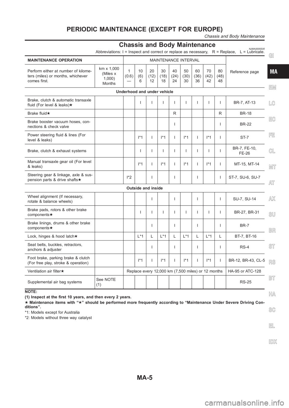
Chassis and Body MaintenanceNJMA0005S05Abbreviations: I = Inspect and correct or replace as necessary, R = Replace, L = Lubricate.
MAINTENANCE OPERATIONMAINTENANCE INTERVAL
Reference page Perform either at number of kilome-
ters (miles) or months, whichever
comes first.kmx1,000
(Miles x
1,000)
Months1
(0.6)
—10
(6)
620
(12)
1230
(18)
1840
(24)
2450
(30)
3060
(36)
3670
(42)
4280
(48)
48
Underhood and under vehicle
Brake, clutch & automatic transaxle
fluid (For level & leaks)★IIIIIIII BR-7,AT-13
Brake fluid★R R BR-18
Brake booster vacuum hoses, con-
nections & check valveI I BR-22
Power steering fluid & lines (For
level & leaks)I*1 I I*1 I I*1 I I*1 I ST-7
Brake, clutch & exhaust systemsIIIIIIIIBR-7, FE-10,
FE-26
Manual transaxle gear oil (For level
& leaks)I*1 I I*1 I I*1 I I*1 I MT-15, MT-14
Steering gear & linkage, axle & sus-
pension parts & drive shafts★I*2IIIIST-7,SU-6,SU-7
Outside and inside
Wheel alignment (If necessary,
rotate & balance wheels)IIIISU-7,SU-14
Brake pads, rotors & other brake
components★IIIIIIII BR-27,BR-31
Brake linings, drums & other brake
components★IIIIBR-7
Lock, hinges & hood latch★L*1 L L*1 L L*1 L L*1 L BT-7, BT-16
Seat belts, buckles, retractors,
anchors & adjusterIIIIRS-4
Foot brake, parking brake & clutch
(For free play, stroke & operation)I*1 I I*1 I I*1 I I*1 I BR-12, BR-43, CL-5
Ventilation air filter★Replace every 12,000 km (7,500 miles) or 12 months HA-95 or ATC-128
Supplemental air bag systemsSee NOTE
(1)RS-25
NOTE:
(1) Inspect at the first 10 years, and then every 2 years.
★Maintenance items with “★” should be performed more frequently according to “Maintenance Under Severe Driving Con-
ditions”.
*1: Models except for Australia
*2: Models without three way catalystGI
EM
LC
EC
FE
CL
MT
AT
AX
SU
BR
ST
RS
BT
HA
SC
EL
IDX
PERIODIC MAINTENANCE (EXCEPT FOR EUROPE)
Chassis and Body Maintenance
MA-5
Page 64 of 3189
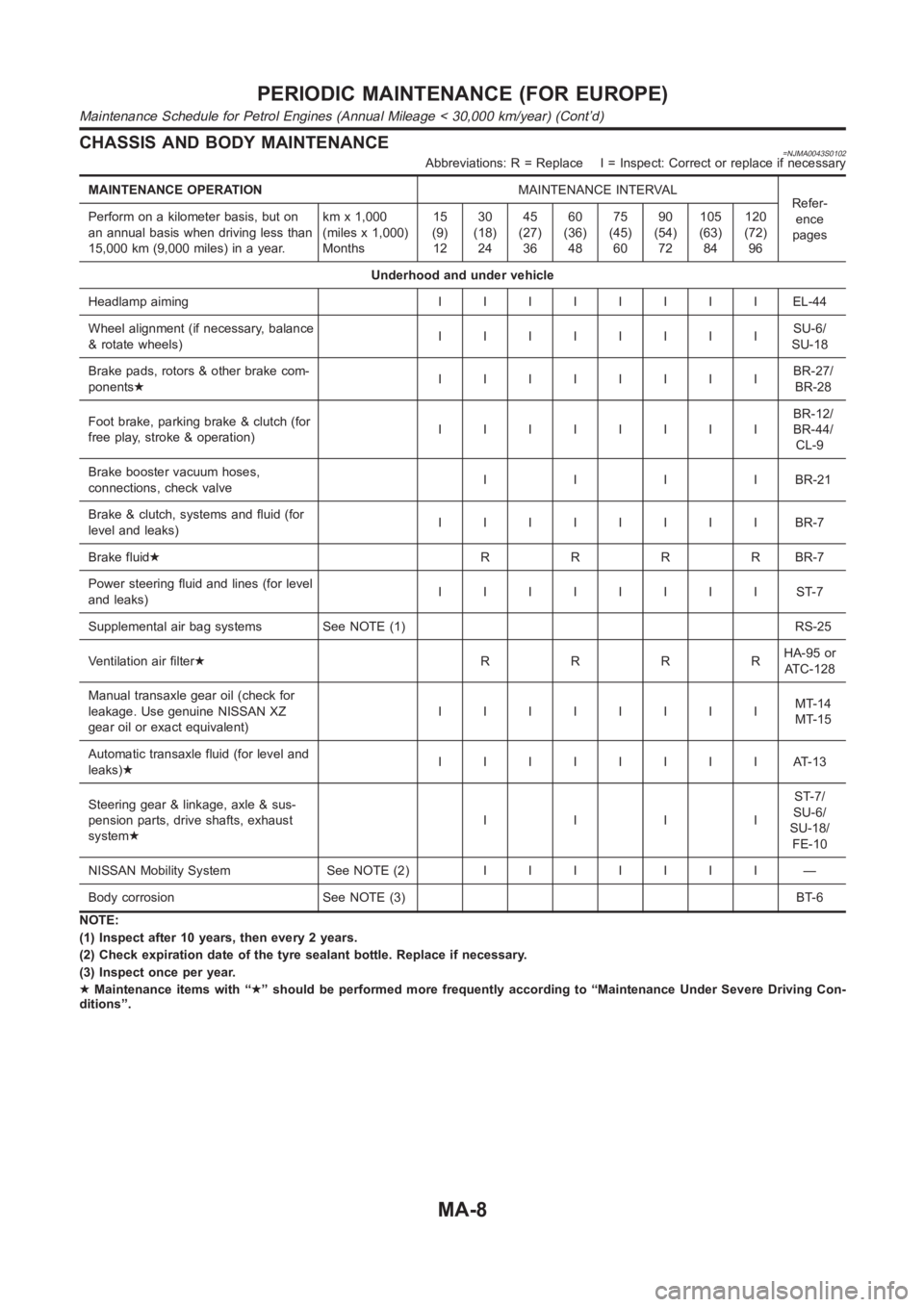
CHASSIS AND BODY MAINTENANCE=NJMA0043S0102Abbreviations: R = Replace I = Inspect: Correct or replace if necessary
MAINTENANCE OPERATIONMAINTENANCE INTERVAL
Refer-
ence
pages Perform on a kilometer basis, but on
an annual basis when driving less than
15,000 km (9,000 miles) in a year.kmx1,000
(miles x 1,000)
Months15
(9)
1230
(18)
2445
(27)
3660
(36)
4875
(45)
6090
(54)
72105
(63)
84120
(72)
96
Underhood and under vehicle
Headlamp aimingIIIIIIIIEL-44
Wheel alignment (if necessary, balance
& rotate wheels)IIIIIIIISU-6/
SU-18
Brake pads, rotors & other brake com-
ponents★IIIIIIIIBR-27/
BR-28
Foot brake, parking brake & clutch (for
free play, stroke & operation)IIIIIIIIBR-12/
BR-44/
CL-9
Brake booster vacuum hoses,
connections, check valveIIIIBR-21
Brake & clutch, systems and fluid (for
level and leaks)IIIIIIIIBR-7
Brake fluid★RRRRBR-7
Power steering fluid and lines (for level
and leaks)IIIIIIIIST-7
Supplemental air bag systems See NOTE (1) RS-25
Ventilation air filter★RRRRHA-95 or
AT C - 1 2 8
Manual transaxle gear oil (check for
leakage. Use genuine NISSAN XZ
gear oil or exact equivalent)IIIIIIIIMT-14
MT-15
Automatic transaxle fluid (for level and
leaks)★IIIIIIIIAT-13
Steering gear & linkage, axle & sus-
pension parts, drive shafts, exhaust
system★IIIIST-7/
SU-6/
SU-18/
FE-10
NISSAN Mobility System See NOTE (2)IIIIIII —
Body corrosion See NOTE (3) BT-6
NOTE:
(1) Inspect after 10 years, then every 2 years.
(2) Check expiration date of the tyre sealant bottle. Replace if necessary.
(3) Inspect once per year.
★Maintenance items with “★” should be performed more frequently according to “Maintenance Under Severe Driving Con-
ditions”.
PERIODIC MAINTENANCE (FOR EUROPE)
Maintenance Schedule for Petrol Engines (Annual Mileage < 30,000 km/year) (Cont’d)
MA-8
Page 66 of 3189
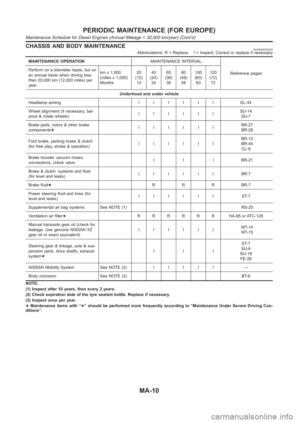
CHASSIS AND BODY MAINTENANCE=NJMA0043S0202Abbreviations: R = Replace I = Inspect: Correct or replace if necessary
MAINTENANCE OPERATIONMAINTENANCE INTERVAL
Reference pages Perform on a kilometer basis, but on
an annual basis when driving less
than 20,000 km (12,000 miles) per
year.kmx1,000
(miles x 1,000)
Months20
(12)
1240
(24)
2460
(36)
3680
(48)
48100
(60)
60120
(72)
72
Underhood and under vehicle
Headlamp aimingIIIIII EL-44
Wheel alignment (if necessary, bal-
ance & rotate wheels)IIIIIISU-14
SU-7
Brake pads, rotors & other brake
components★IIIIIIBR-27
BR-28
Foot brake, parking brake & clutch
(for free play, stroke & operation)IIIIIIBR-12
BR-44
CL-9
Brake booster vacuum hoses,
connections, check valveI I I BR-21
Brake & clutch, systems and fluid
(for level and leaks)IIIIII BR-7
Brake fluid★R R R BR-7
Power steering fluid and lines (for
level and leaks)IIIIII ST-7
Supplemental air bag systems See NOTE (1) RS-25
Ventilation air filter★RRRRRR HA-95orATC-128
Manual transaxle gear oil (check for
leakage. Use genuine NISSAN XZ
gear oil or exact equivalent)IIIIIIMT-14
MT-15
Steering gear & linkage, axle & sus-
pension parts, drive shafts, exhaust
system★IIIST-7
SU-6
SU-18
FE-26
NISSAN Mobility System See NOTE (2)IIIII —
Body corrosion See NOTE (3) BT-6
NOTE:
(1) Inspect after 10 years, then every 2 years.
(2) Check expiration date of the tyre sealant bottle. Replace if necessary.
(3) Inspect once per year.
★Maintenance items with “★” should be performed more frequently according to “Maintenance Under Severe Driving Con-
ditions”.
PERIODIC MAINTENANCE (FOR EUROPE)
Maintenance Schedule for Diesel Engines (Annual Mileage < 30,000 km/year) (Cont’d)
MA-10
Page 70 of 3189
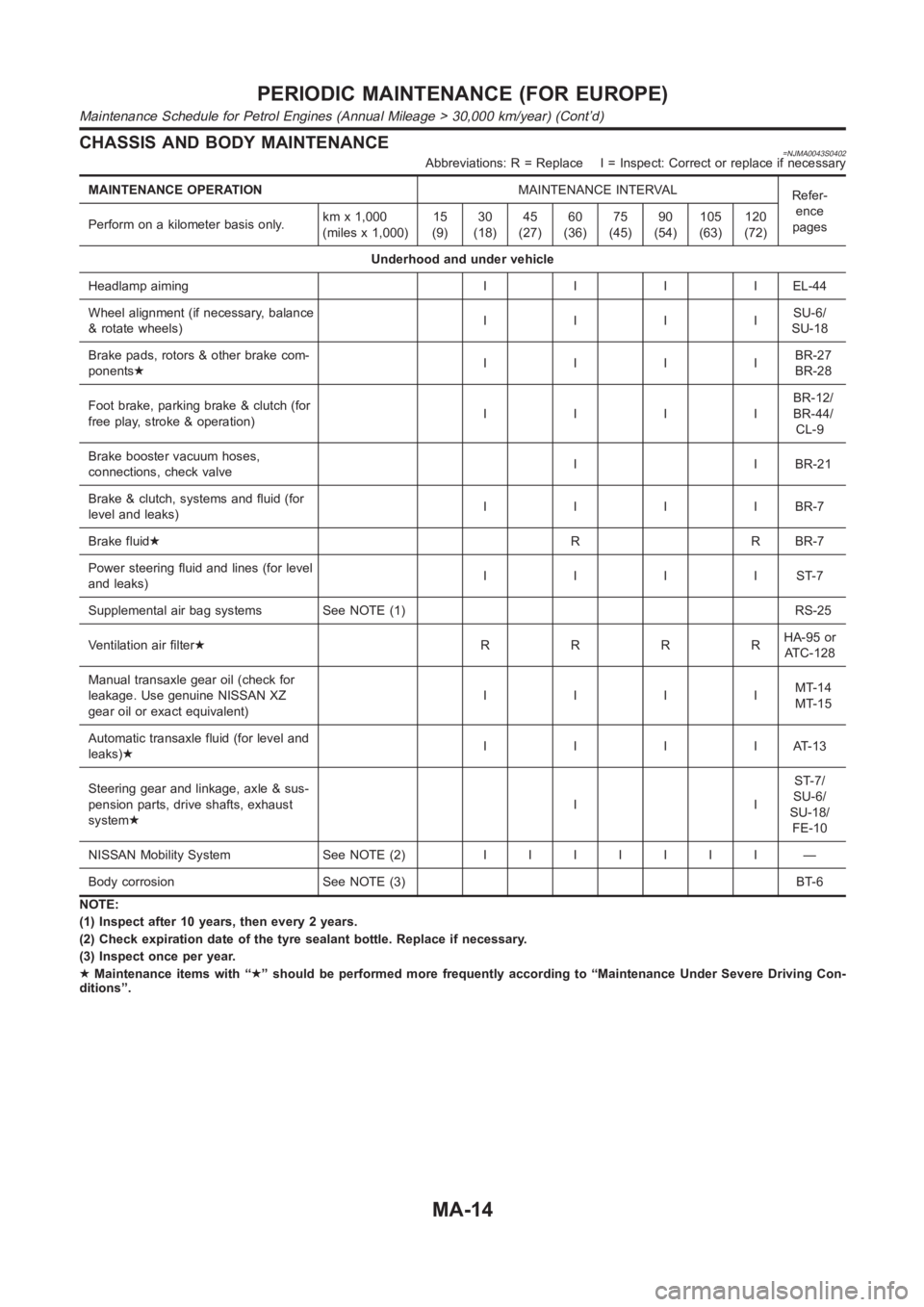
CHASSIS AND BODY MAINTENANCE=NJMA0043S0402Abbreviations: R = Replace I = Inspect: Correct or replace if necessary
MAINTENANCE OPERATIONMAINTENANCE INTERVAL
Refer-
ence
pages Perform on a kilometer basis only.kmx1,000
(miles x 1,000)15
(9)30
(18)45
(27)60
(36)75
(45)90
(54)105
(63)120
(72)
Underhood and under vehicle
Headlamp aimingIIIIEL-44
Wheel alignment (if necessary, balance
& rotate wheels)IIIISU-6/
SU-18
Brake pads, rotors & other brake com-
ponents★IIIIBR-27
BR-28
Foot brake, parking brake & clutch (for
free play, stroke & operation)IIIIBR-12/
BR-44/
CL-9
Brake booster vacuum hoses,
connections, check valveI I BR-21
Brake & clutch, systems and fluid (for
level and leaks)IIIIBR-7
Brake fluid★R R BR-7
Power steering fluid and lines (for level
and leaks)IIIIST-7
Supplemental air bag systems See NOTE (1) RS-25
Ventilation air filter★RRRRHA-95 or
AT C - 1 2 8
Manual transaxle gear oil (check for
leakage. Use genuine NISSAN XZ
gear oil or exact equivalent)IIIIMT-14
MT-15
Automatic transaxle fluid (for level and
leaks)★IIIIAT-13
Steering gear and linkage, axle & sus-
pension parts, drive shafts, exhaust
system★IIST-7/
SU-6/
SU-18/
FE-10
NISSAN Mobility System See NOTE (2)IIIIIII —
Body corrosion See NOTE (3) BT-6
NOTE:
(1) Inspect after 10 years, then every 2 years.
(2) Check expiration date of the tyre sealant bottle. Replace if necessary.
(3) Inspect once per year.
★Maintenance items with “★” should be performed more frequently according to “Maintenance Under Severe Driving Con-
ditions”.
PERIODIC MAINTENANCE (FOR EUROPE)
Maintenance Schedule for Petrol Engines (Annual Mileage > 30,000 km/year) (Cont’d)
MA-14
Page 72 of 3189
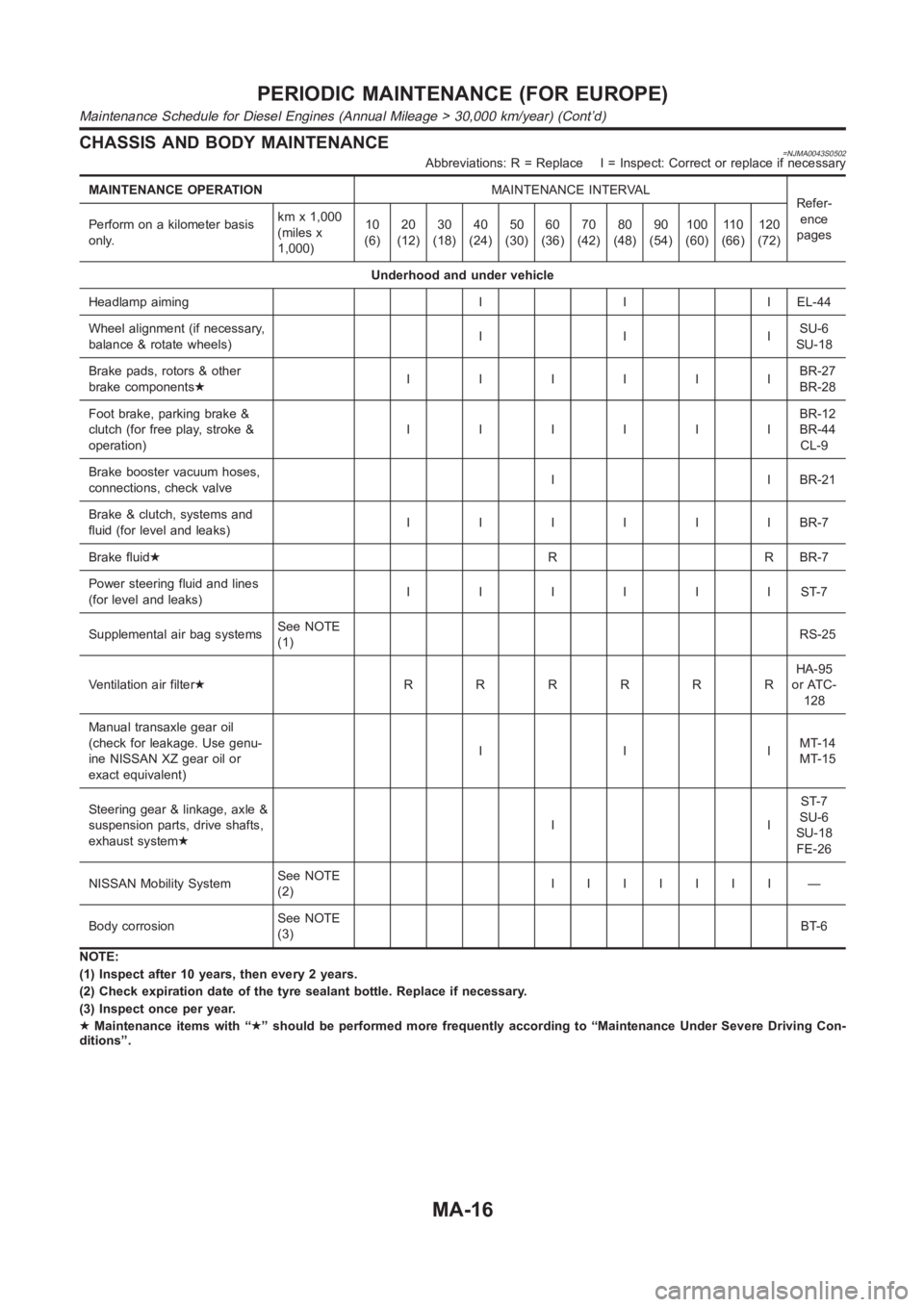
CHASSIS AND BODY MAINTENANCE=NJMA0043S0502Abbreviations: R = Replace I = Inspect: Correct or replace if necessary
MAINTENANCE OPERATIONMAINTENANCE INTERVAL
Refer-
ence
pages Perform on a kilometer basis
only.kmx1,000
(miles x
1,000)10
(6)20
(12)30
(18)40
(24)50
(30)60
(36)70
(42)80
(48)90
(54)100
(60)11 0
(66)120
(72)
Underhood and under vehicle
Headlamp aiming I I I EL-44
Wheel alignment (if necessary,
balance & rotate wheels)IIISU-6
SU-18
Brake pads, rotors & other
brake components★IIIIIIBR-27
BR-28
Foot brake, parking brake &
clutch (for free play, stroke &
operation)IIIIIIBR-12
BR-44
CL-9
Brake booster vacuum hoses,
connections, check valveI I BR-21
Brake & clutch, systems and
fluid (for level and leaks)IIIIIIBR-7
Brake fluid★R R BR-7
Power steering fluid and lines
(for level and leaks)IIIIIIST-7
Supplemental air bag systemsSee NOTE
(1)RS-25
Ventilation air filter★RRRRRRHA-95
or ATC-
128
Manual transaxle gear oil
(check for leakage. Use genu-
ine NISSAN XZ gear oil or
exact equivalent)IIIMT-14
MT-15
Steering gear & linkage, axle &
suspension parts, drive shafts,
exhaust system★IIST-7
SU-6
SU-18
FE-26
NISSAN Mobility SystemSee NOTE
(2)IIIIIII —
Body corrosionSee NOTE
(3)BT-6
NOTE:
(1) Inspect after 10 years, then every 2 years.
(2) Check expiration date of the tyre sealant bottle. Replace if necessary.
(3) Inspect once per year.
★Maintenance items with “★” should be performed more frequently according to “Maintenance Under Severe Driving Con-
ditions”.
PERIODIC MAINTENANCE (FOR EUROPE)
Maintenance Schedule for Diesel Engines (Annual Mileage > 30,000 km/year) (Cont’d)
MA-16
Page 133 of 3189
![NISSAN ALMERA N16 2003 Electronic Repair Manual OIL SEAL
EM-55
[QG]
C
D
E
F
G
H
I
J
K
L
MA
EM
Removal and Installation of Front Oil SealEBS00LQF
REMOVAL
1. Remove the following parts:
●Undercover (with splash cover)
●Drive belt; Refer to EM-11, NISSAN ALMERA N16 2003 Electronic Repair Manual OIL SEAL
EM-55
[QG]
C
D
E
F
G
H
I
J
K
L
MA
EM
Removal and Installation of Front Oil SealEBS00LQF
REMOVAL
1. Remove the following parts:
●Undercover (with splash cover)
●Drive belt; Refer to EM-11,](/img/5/57350/w960_57350-132.png)
OIL SEAL
EM-55
[QG]
C
D
E
F
G
H
I
J
K
L
MA
EM
Removal and Installation of Front Oil SealEBS00LQF
REMOVAL
1. Remove the following parts:
●Undercover (with splash cover)
●Drive belt; Refer to EM-11, "DRIVE BELTS" .
●Crankshaft pulley; Refer to EM-47, "TIMING CHAIN" .
2. Using flat-head screwdriver, remove front oil seal.
CAUTION:
Be careful not to damage front timing chain cover and crankshaft.
INSTALLATION
1. Apply engine oil on new front oil seal.
2. Using a suitable drift, press fit until the height of front oil seal is
level with the mounting surface.
●Suitable drift : outer diameter 50 mm (1.97 in), inner diameter
44 mm (1.73 in).
CAUTION:
●Be careful not to damage front cover and crankshaft.
●Press oil seal straight so that it is not curling up or
inclined.
3. Perform steps in the reverse order of removal for the following
operations.
Removal and Installation of Rear Oil SealEBS00LQG
REMOVAL
1. Remove transaxle assembly. Refer to MT-23, "Removal" (RS5F30A), MT-23, "Removal" (RS5F70A) and
AT-411, "Removal" (AUTOMATIC TRANSAXLE).
2. Remove drive plate. Refer to EM-70, "
CYLINDER BLOCK" .
3. Using flat-head screwdriver, remove front oil seal.
CAUTION:
Be careful not to damage mounting surface.
INSTALLATION
1. Using a suitable drift, press rear oil seal to rear oil seal retainer.
●Suitable drift : outer diameter 102 mm (4.02 in), inner diame-
ter 90 mm (3.54 in).
CAUTION:
●Do not touch grease applied on oil seal lip
●Be careful not to damage rear oil seal retainer and crank-
shaft.
●Press in straight to avoid causing any burrs or tilting of
oil seal.
SEM912F
SEM715A
SEM097F
Page 146 of 3189
![NISSAN ALMERA N16 2003 Electronic Repair Manual EM-68
[QG]
ENGINE ASSEMBLY
WARNING:
●Position vehicle on a flat and solid surface.
●Place chocks at front and back of rear wheels.
●Do not remove engine until exhaust system has complete NISSAN ALMERA N16 2003 Electronic Repair Manual EM-68
[QG]
ENGINE ASSEMBLY
WARNING:
●Position vehicle on a flat and solid surface.
●Place chocks at front and back of rear wheels.
●Do not remove engine until exhaust system has complete](/img/5/57350/w960_57350-145.png)
EM-68
[QG]
ENGINE ASSEMBLY
WARNING:
●Position vehicle on a flat and solid surface.
●Place chocks at front and back of rear wheels.
●Do not remove engine until exhaust system has completely cooled off, otherwise, you may burn
yourself and/or fire may break out in fuel line.
●Before disconnecting fuel hose, release pressure.
Refer to EC-34 (WITH EURO-OBD), EC-428 (WITHOUT EURO-OBD).
●Be sure to lift engine and transaxle in a safe manner.
●For engines not equipped with engine slingers, attach proper slingers and bolts described in
PARTS CATALOG.
CAUTION:
●When lifting engine, be sure to clear surrounding parts. Use special care near accelerator wire
casing, brake lines and brake master cylinder.
●When lifting the engine, always use engine slingers in a safe manner.
●When removing drive shaft, be careful not to damage grease seal of transaxle.
●Before separating engine and transaxle, remove crankshaft position sensor (POS) from the cylin-
der block assembly.
●Always be extra careful not to damage edge of crankshaft position sensor (POS), or signal plate
teeth.
Engine cannot be removed separately from transaxle. Remove engine with transaxle as an assembly.
REMOVAL
1. Drain coolant from radiator and cylinder block. Refer to LC-17, "Chacking Engine Coolant".
2. Remove coolant reservoir tank and bracket.
3. Drain engine oil.
4. Remove battery and battery tray.
5. Remove air cleaner and air duct.
6. Remove drive belts.
7. Remove alternator and air conditioner compressor from engine.
8. Remove power steering oil pump from engine and position aside.
Power steering oil pump does not need to be disconnected from power steering tubes.
9. Remove the following parts:
●RH and LH front tires
●Splash covers
●RH and LH brake caliper assemblies
Refer to BR-28,"Removal".
Brake hose does not need to be disconnected from brake
caliper assembly. Never depress brake pedal.
●RH & LH drive shaft. Refer to AX-11, "Removal".
When removing drive shaft, be careful not to damage
transaxle side grease seal.
●Disconnect control rod and support rod from transaxle. (M/T
models.)
Refer to MT-26, "Removal".
●Disconnect control cable from transaxle. (A/T models.)
Refer to AT-411, "Removal".
SEM174D
SEM109G
Page 202 of 3189
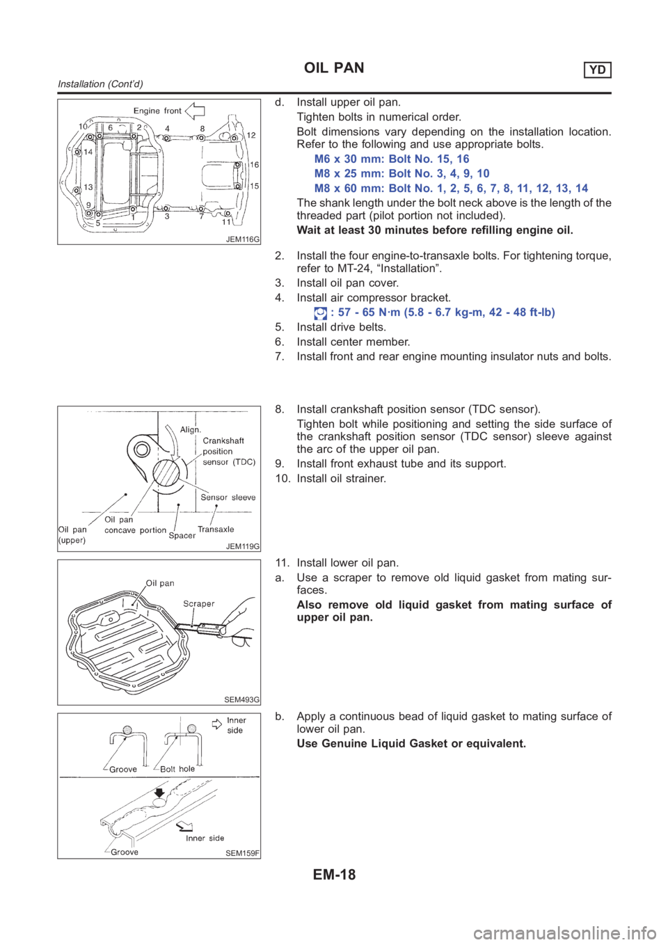
JEM116G
d. Install upper oil pan.
Tighten bolts in numerical order.
Bolt dimensions vary depending on the installation location.
Refer to the following and use appropriate bolts.
M6 x 30 mm: Bolt No. 15, 16
M8x25mm:BoltNo.3,4,9,10
M8x60mm:BoltNo.1,2,5,6,7,8,11,12,13,14
The shank length under the bolt neck above is the length of the
threaded part (pilot portion not included).
Wait at least 30 minutes before refilling engine oil.
2. Install the four engine-to-transaxle bolts. For tightening torque,
refer to MT-24, “Installation”.
3. Install oil pan cover.
4. Install air compressor bracket.
: 57 - 65 N·m (5.8 - 6.7 kg-m, 42 - 48 ft-lb)
5. Install drive belts.
6. Install center member.
7. Install front and rear engine mounting insulator nuts and bolts.
JEM119G
8. Install crankshaft position sensor (TDC sensor).
Tighten bolt while positioning and setting the side surface of
the crankshaft position sensor (TDC sensor) sleeve against
the arc of the upper oil pan.
9. Install front exhaust tube and its support.
10. Install oil strainer.
SEM493G
11. Install lower oil pan.
a. Use a scraper to remove old liquid gasket from mating sur-
faces.
Also remove old liquid gasket from mating surface of
upper oil pan.
SEM159F
b. Apply a continuous bead of liquid gasket to mating surface of
lower oil pan.
Use Genuine Liquid Gasket or equivalent.
OIL PANYD
Installation (Cont’d)
EM-18
Page 402 of 3189
![NISSAN ALMERA N16 2003 Electronic Repair Manual EC-72
[QG (WITH EURO-OBD)]
TROUBLE DIAGNOSIS
Air Air duct
55555 5EM-14
Air cleanerEM-14
Air leakage from air duct
(Mass air flow sensor —electric
throttle control actuator)
5555EM-14
Electric throt NISSAN ALMERA N16 2003 Electronic Repair Manual EC-72
[QG (WITH EURO-OBD)]
TROUBLE DIAGNOSIS
Air Air duct
55555 5EM-14
Air cleanerEM-14
Air leakage from air duct
(Mass air flow sensor —electric
throttle control actuator)
5555EM-14
Electric throt](/img/5/57350/w960_57350-401.png)
EC-72
[QG (WITH EURO-OBD)]
TROUBLE DIAGNOSIS
Air Air duct
55555 5EM-14
Air cleanerEM-14
Air leakage from air duct
(Mass air flow sensor —electric
throttle control actuator)
5555EM-14
Electric throttle control actuatorEM-16
Air leakage from intake manifold/
Collector/GasketEM-16
Cranking Battery
111111 11SC-3
Alternator circuitSC-27
Starter circuit 3 SC-13
Signal plate/Flywheel/Drive plate 6EM-70
PNP switch
4AT- 11 6,
MT-21
Engine Cylinder head
55555 55 5EM-57
Cylinder head gasket 4 3
Cylinder block
66666 66 64
EM-70
Piston
Piston ring
Connecting rod
Bearing
Crankshaft
Va l v e
mecha-
nismTimin g c hain
55555 55 5EM-47
CamshaftEM-32
Intake valve timing controlEM-47
Intake valve
3EM-57
Exhaust valve
Exhaust Exhaust manifold/Tube/Muffler/
Gasket
55555 55 5EM-19
, FE-
26
Three way catalyst
Lubrica-
tionOil pan/Oil strainer/Oil pump/Oil
filter/Oil gallery
55555 55 52EM-22
, LC-
5, LC-9,
LC-4
Oil level (Low)/Filthy oilLC-8 SYMPTOM
Reference
page
HARD/NO START/RESTART (EXCP. HA)
ENGINE STALL
HESITATION/SURGING/FLAT SPOT
SPARK KNOCK/DETONATION
LACK OF POWER/POOR ACCELERATION
HIGH IDLE/LOW IDLE
ROUGH IDLE/HUNTING
IDLING VIBRATION
SLOW/NO RETURN TO IDLE
OVERHEATS/WATER TEMPERATURE HIGH
EXCESSIVE FUEL CONSUMPTION
EXCESSIVE OIL CONSUMPTION
BATTERY DEAD (UNDER CHARGE)
Warranty symptom code AA AB AC AD AE AF AG AH AJ AK AL AM HA
Page 689 of 3189
![NISSAN ALMERA N16 2003 Electronic Repair Manual DTC P1706 PNP SWITCH
EC-359
[QG (WITH EURO-OBD)]
C
D
E
F
G
H
I
J
K
L
MA
EC
Specification data are reference values and are measured between each terminal and ground.
CAUTION:
Do not use ECM ground ter NISSAN ALMERA N16 2003 Electronic Repair Manual DTC P1706 PNP SWITCH
EC-359
[QG (WITH EURO-OBD)]
C
D
E
F
G
H
I
J
K
L
MA
EC
Specification data are reference values and are measured between each terminal and ground.
CAUTION:
Do not use ECM ground ter](/img/5/57350/w960_57350-688.png)
DTC P1706 PNP SWITCH
EC-359
[QG (WITH EURO-OBD)]
C
D
E
F
G
H
I
J
K
L
MA
EC
Specification data are reference values and are measured between each terminal and ground.
CAUTION:
Do not use ECM ground terminals when measuring input/output voltage. Doing so may result in dam-
age to the ECM's transistor. Use a ground other than ECM terminals, such as the ground.
Diagnostic ProcedureEBS00KCK
1.CHECK PNP SWITCH GROUND CIRCUIT FOR OPEN AND SHORT
1. Turn ignition switch “OFF”.
2. Disconnect PNP switch harness connector.
3. Check harness continuity between PNP switch terminal 2 and
body ground.
Refer to Wiring Diagram.
4. Also check harness for short to power.
OK or NG
OK >> GO TO 2.
NG >> Repair open circuit or short to power in harness or con-
nectors.
2.CHECK PNP SWITCH INPUT SIGNAL CIRCUIT FOR OPEN AND SHORT
1. Disconnect ECM harness connector.
2. Check harness continuity between ECM terminal 102 and PNP switch terminal 1.
Refer to Wiring Diagram.
3. Also check harness for short to ground and short to power.
OK or NG
OK >> GO TO 3.
NG >> Repair open circuit or short to ground or short to power in harness or connectors.
3.CHECK PNP SWITCH
Refer to AT- 111 , "
DTC P0705 PARK/NEUTRAL POSITION (PNP) SWITCH" (A/T models) or MT-21 (M/T
models).
OK or NG
OK >> GO TO 4.
NG >> Replace PNP switch.
4.CHECK INTERMITTENT INCIDENT
Refer to EC-109, "
TROUBLE DIAGNOSIS FOR INTERMITTENT INCIDENT" .
>>INSPECTION END
TER-
MINAL
NO.WIRE
COLORITEM CONDITION DATA (DC Voltage)
102P (A/T)
G/OR (M/T)PNP switch[Ignition switch “ON”]
●Shift lever position is “P” or “N” (A/T models).
●Shift lever position is ″Neutral″ (M/T models).Approximately 0V
[Ignition switch “ON”]
●Except the above gear positionA/T models
BATTERY VOLTAGE
(11 - 14V)
M/T models
Approximately 5V
Continuity should exist.
MBIB0253E
Continuity should exist.