Resistor NISSAN ALMERA N16 2003 Electronic Repair Manual
[x] Cancel search | Manufacturer: NISSAN, Model Year: 2003, Model line: ALMERA N16, Model: NISSAN ALMERA N16 2003Pages: 3189, PDF Size: 54.76 MB
Page 1186 of 3189

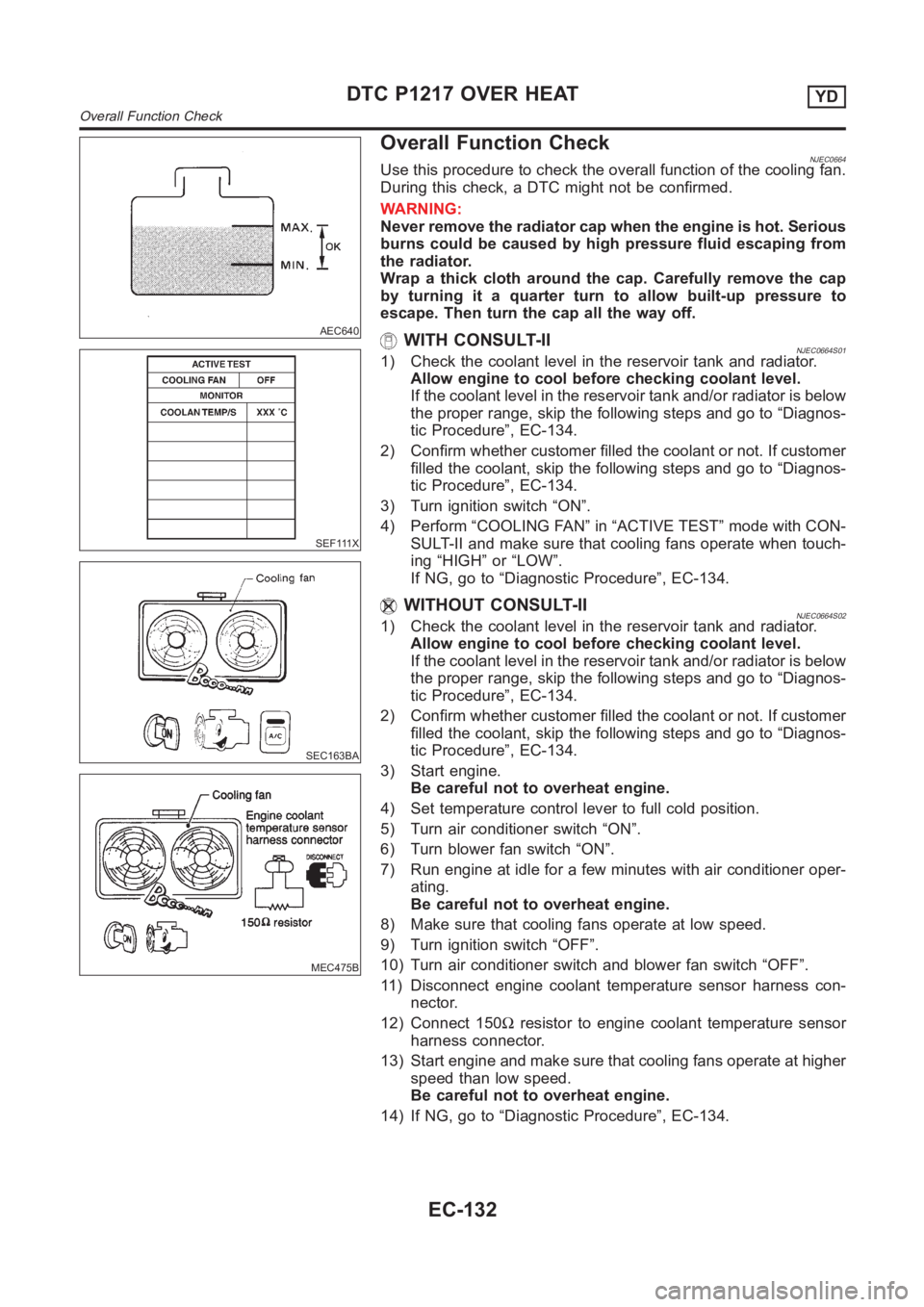
AEC640
Overall Function Check
SEF111X
SEC163BA
MEC475B
NJEC0664Use this procedure to check the overall function of the cooling fan.
During this check, a DTC might not be confirmed.
WARNING:
Never remove the radiator cap when the engine is hot. Serious
burns could be caused by high pressure fluid escaping from
the radiator.
Wrap a thick cloth around the cap. Carefully remove the cap
by turning it a quarter turn to allow built-up pressure to
escape. Then turn the cap all the way off.
WITH CONSULT-IINJEC0664S011) Check the coolant level in the reservoir tank and radiator.
Allow engine to cool before checking coolant level.
If the coolant level in the reservoir tank and/or radiator is below
the proper range, skip the following steps and go to “Diagnos-
tic Procedure”, EC-134.
2) Confirm whether customer filled the coolant or not. If customer
filled the coolant, skip the following steps and go to “Diagnos-
tic Procedure”, EC-134.
3) Turn ignition switch “ON”.
4) Perform “COOLING FAN” in “ACTIVE TEST” mode with CON-
SULT-II and make sure that cooling fans operate when touch-
ing “HIGH” or “LOW”.
If NG, go to “Diagnostic Procedure”, EC-134.
WITHOUT CONSULT-IINJEC0664S021) Check the coolant level in the reservoir tank and radiator.
Allow engine to cool before checking coolant level.
If the coolant level in the reservoir tank and/or radiator is below
the proper range, skip the following steps and go to “Diagnos-
tic Procedure”, EC-134.
2) Confirm whether customer filled the coolant or not. If customer
filled the coolant, skip the following steps and go to “Diagnos-
tic Procedure”, EC-134.
3) Start engine.
Be careful not to overheat engine.
4) Set temperature control lever to full cold position.
5) Turn air conditioner switch “ON”.
6) Turn blower fan switch “ON”.
7) Run engine at idle for a few minutes with air conditioner oper-
ating.
Be careful not to overheat engine.
8) Make sure that cooling fans operate at low speed.
9) Turn ignition switch “OFF”.
10) Turn air conditioner switch and blower fan switch “OFF”.
11) Disconnect engine coolant temperature sensor harness con-
nector.
12) Connect 150Ωresistor to engine coolant temperature sensor
harness connector.
13) Start engine and make sure that cooling fans operate at higher
speed than low speed.
Be careful not to overheat engine.
14) If NG, go to “Diagnostic Procedure”, EC-134.
DTC P1217 OVER HEATYD
Overall Function Check
EC-132
Page 1190 of 3189

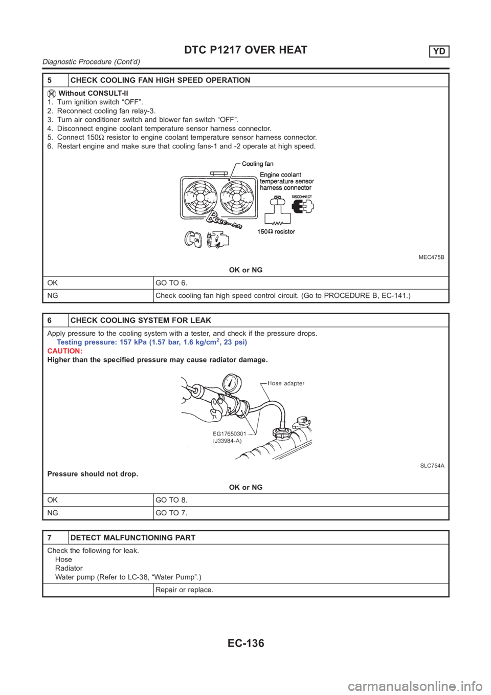
5 CHECK COOLING FAN HIGH SPEED OPERATION
Without CONSULT-II
1. Turn ignition switch “OFF”.
2. Reconnect cooling fan relay-3.
3. Turn air conditioner switch and blower fan switch “OFF”.
4. Disconnect engine coolant temperature sensor harness connector.
5. Connect 150Ωresistor to engine coolant temperature sensor harness connector.
6. Restart engine and make sure that cooling fans-1 and -2 operate at high speed.
MEC475B
OK or NG
OK GO TO 6.
NG Check cooling fan high speed control circuit. (Go to PROCEDURE B, EC-141.)
6 CHECK COOLING SYSTEM FOR LEAK
Apply pressure to the cooling system with a tester, and check if the pressure drops.
Testing pressure: 157 kPa (1.57 bar, 1.6 kg/cm2,23psi)
CAUTION:
Higher than the specified pressure may cause radiator damage.
SLC754A
Pressure should not drop.
OK or NG
OK GO TO 8.
NG GO TO 7.
7 DETECT MALFUNCTIONING PART
Check the following for leak.
Hose
Radiator
Water pump (Refer to LC-38, “Water Pump”.)
Repair or replace.
DTC P1217 OVER HEATYD
Diagnostic Procedure (Cont’d)
EC-136
Page 1460 of 3189

AT-4
REMOVAL AND INSTALLATION ...........................410
Removal ...............................................................410
Installation .............................................................411
OVERHAUL .............................................................413
Output Shaft, Idler Gear, Reduction Pinion Gear and
Bearing Retainer ...................................................413
Oil Channel ...........................................................416
Locations of Adjusting Shims, Needle Bearings,
Thrust Washers and Snap Rings ..........................417
DISASSEMBLY .......................................................418
Disassembly .........................................................418
REPAIR FOR COMPONENT PARTS ......................432
Manual Shaft ........................................................432
Oil Pump ...............................................................435
Control Valve Assembly ........................................439
Control Valve Upper Body ....................................449
Control Valve Lower Body ....................................453
Reverse Clutch .....................................................455
High Clutch ...........................................................459
Forward and Overrun Clutches ............................464
Low & Reverse Brake ...........................................470
Rear Internal Gear, Forward Clutch Hub and Over-
run Clutch Hub ......................................................474
Output Shaft, Idler Gear, Reduction Pinion Gear and
Bearing Retainer ...................................................478
Band Servo Piston Assembly ...............................483
Final Drive ............................................................488
ASSEMBLY .............................................................493
Assembly (1) .........................................................493Adjustment (1) .......................................................494
Assembly (2) .........................................................500
Adjustment (2) .......................................................504
Assembly (3) .........................................................508
SERVICE DATA AND SPECIFICATIONS (SDS) ....515
General Specifications ......................................... .515
Shift Schedule .......................................................515
Stall Revolution .....................................................515
Line Pressure ........................................................515
Control Valves .......................................................516
Clutch and Brakes .................................................516
Clutch and Brake Return Springs .........................518
Oil Pump ......................................................
.........518
Input Shaft .............................................................518
Planetary carrier ....................................................518
Final Drive .............................................................519
Reduction Pinion Gear ..........................................520
Output Shaft ..........................................................522
Bearing Retainer ...................................................523
Total End Play .......................................................523
Reverse Clutch End Play ......................................523
Accumulator ..........................................................523
Band Servo ...........................................................524
Removal and Installation .......................................524
Shift Solenoid Valves ............................................524
Solenoid Valves ....................................................524
A/T Fluid Temperature Sensor ..............................524
Revolution Sensor .................................................524
Dropping Resistor .................................................524
Page 1524 of 3189
![NISSAN ALMERA N16 2003 Electronic Repair Manual AT-68
[EURO-OBD]
TROUBLE DIAGNOSIS — BASIC INSPECTION
JUDGEMENT OF LINE PRESSURE TEST
Road TestECS007NZ
DESCRIPTION
●The purpose of the test is to determine overall performance of A/
T and analyze NISSAN ALMERA N16 2003 Electronic Repair Manual AT-68
[EURO-OBD]
TROUBLE DIAGNOSIS — BASIC INSPECTION
JUDGEMENT OF LINE PRESSURE TEST
Road TestECS007NZ
DESCRIPTION
●The purpose of the test is to determine overall performance of A/
T and analyze](/img/5/57350/w960_57350-1523.png)
AT-68
[EURO-OBD]
TROUBLE DIAGNOSIS — BASIC INSPECTION
JUDGEMENT OF LINE PRESSURE TEST
Road TestECS007NZ
DESCRIPTION
●The purpose of the test is to determine overall performance of A/
T and analyze causes of problems.
●The road test consists of the following three parts:
1. Check before engine is started
2. Check at idle
3. Cruise test
●Before road test, familiarize yourself with all test procedures and
items to check.
●Conduct tests on all items until specified symptom is found.
Troubleshoot items which check out No Good after road test.
Refer to the following items.
Judgement Suspected parts
At idleLine pressure is low in all positions.
●Oil pump wear
●Control piston damage
●Pressure regulator valve or plug sticking
●Spring for pressure regulator valve damaged
●Line pressure leakage between oil strainer and pressure regulator valve
●Clogged strainer
Line pressure is low in particular posi-
tion.
●Line pressure leakage between manual valve and particular clutch
●For example, line pressure is:
− Low in “R” and “1” positions, but
− Normal in “D” and “2” positions.
Therefore, fluid leakage exists at or around low and reverse brake circuit.
Refer to AT- 1 8 , "
Shift Mechanism" .
Line pressure is high.
●Maladjustment of throttle position sensor
●A/T fluid temperature sensor damaged
●Line pressure solenoid valve sticking
●Short circuit of line pressure solenoid valve circuit
●Pressure modifier valve sticking
●Pressure regulator valve or plug sticking
●Open in dropping resistor circuit
At stall
speedLine pressure is low.
●Maladjustment of throttle position sensor
●Line pressure solenoid valve sticking
●Short circuit of line pressure solenoid valve circuit
●Pressure regulator valve or plug sticking
●Pressure modifier valve sticking
●Pilot valve sticking
SAT786A
SAT496G
Page 1562 of 3189
![NISSAN ALMERA N16 2003 Electronic Repair Manual AT-106
[EURO-OBD]
TROUBLE DIAGNOSIS — GENERAL DESCRIPTION
CONSULT-II REFERENCE VALUE IN DATA MONITOR MODE
Remarks: Specification data are reference values.
TCM Terminals and Reference ValueECS007O1
NISSAN ALMERA N16 2003 Electronic Repair Manual AT-106
[EURO-OBD]
TROUBLE DIAGNOSIS — GENERAL DESCRIPTION
CONSULT-II REFERENCE VALUE IN DATA MONITOR MODE
Remarks: Specification data are reference values.
TCM Terminals and Reference ValueECS007O1](/img/5/57350/w960_57350-1561.png)
AT-106
[EURO-OBD]
TROUBLE DIAGNOSIS — GENERAL DESCRIPTION
CONSULT-II REFERENCE VALUE IN DATA MONITOR MODE
Remarks: Specification data are reference values.
TCM Terminals and Reference ValueECS007O1
PREPARATION
●Measure voltage between each terminal and terminal 25 or 48
by following “TCM INSPECTION TABLE”.
TCM HARNESS CONNECTOR TERMINAL LAYOUT
TCM INSPECTION TABLE
(Data are reference values.)
Monitor item Condition Specification (Approximately)
A/T fluid temperature sensorCold [20°C (68°F)]
↓
Hot [80°C (176°F)]1.5V
↓
0.5V2.5kΩ
↓
0.3kΩ
Line pressure solenoid valve dutySmall throttle opening
(Low line pressure)
↓
Large throttle opening
(High line pressure)Approximately 24%
↓
Approximately 95%
Torque converter clutch solenoid valve dutyLock-up “OFF”
↓
Lock-up “ON”Approximately 4%
↓
Approximately 94%
Throttle position sensor (Accelerator pedal
position (APP) sensor)Fully-closed throttle Approximately 0.5V
Fully-open throttle Approximately 4V
SAT216J
SAT999J
Te r m i -
nal No.Wire color Item ConditionJudgement stan-
dard(Approx.)
1R/WLine pressure
solenoid valveWhen releasing accelerator pedal
after warming up engine.1.5 - 3.0V
When depressing accelerator pedal
fully after warming up engine.0V
2P/BLine pressure
solenoid valve
(with dropping
resistor)When releasing accelerator pedal
after warming up engine.4 - 14V
When depressing accelerator pedal
fully after warming up engine.0V
Page 1587 of 3189
![NISSAN ALMERA N16 2003 Electronic Repair Manual DTC P0725 ENGINE SPEED SIGNAL
AT-131
[EURO-OBD]
D
E
F
G
H
I
J
K
L
MA
B
AT
Diagnostic ProcedureECS007OH
1.CHECK DTC WITH ECM
Perform “Overall function check” for ignition signal. Refer to EC-369, & NISSAN ALMERA N16 2003 Electronic Repair Manual DTC P0725 ENGINE SPEED SIGNAL
AT-131
[EURO-OBD]
D
E
F
G
H
I
J
K
L
MA
B
AT
Diagnostic ProcedureECS007OH
1.CHECK DTC WITH ECM
Perform “Overall function check” for ignition signal. Refer to EC-369, &](/img/5/57350/w960_57350-1586.png)
DTC P0725 ENGINE SPEED SIGNAL
AT-131
[EURO-OBD]
D
E
F
G
H
I
J
K
L
MA
B
AT
Diagnostic ProcedureECS007OH
1.CHECK DTC WITH ECM
Perform “Overall function check” for ignition signal. Refer to EC-369, "
Diagnostic Procedure" .
OK or NG
OK (With CONSULT-II)>>GO TO 2
OK (Without CONSULT-II)>>GO TO 3
NG >> Follow the construction of EC-369, "
Diagnostic Procedure" .
2.CHECK INPUT SIGNAL (WITH CONSULT-II)
With CONSULT-II
1. Start engine.
2. Select “TCM INPUT SIGNALS” in “DATA MONITOR” mode for
“A/T” with CONSULT-II.
3. Read out the value of “ENGINE SPEED”.
Check engine speed changes according to throttle position.
OK or NG
OK >> GO TO 4
NG >> Check the following items:
●Harness for short or open between TCM and ECM
●Resistor and ignition coil Refer to EC-365, "IGNITION
SIGNAL" .
3.CHECK INPUT SIGNAL (WITHOUT CONSULT-II)
Without CONSULT-II
1. Start engine.
2. Check voltage between TCM terminal 39 and ground.
OK or NG
OK >> GO TO 4
NG >> Check the following items:
●Harness for short or open between TCM and ECM
●Resistor and ignition coil EC-365, "IGNITION SIG-
NAL" .
SAT014K
SAT645J
Voltage (Idle speed): Refer to EC-65, "Basic Inspection" .
SCIA0740E
Page 1607 of 3189
![NISSAN ALMERA N16 2003 Electronic Repair Manual DTC P0734 A/T 4TH GEAR FUNCTION
AT-151
[EURO-OBD]
D
E
F
G
H
I
J
K
L
MA
B
AT
DTC P0734 A/T 4TH GEAR FUNCTIONPFP:31940
DescriptionECS007OU
●This is an OBD-II self-diagnostic item and not available in NISSAN ALMERA N16 2003 Electronic Repair Manual DTC P0734 A/T 4TH GEAR FUNCTION
AT-151
[EURO-OBD]
D
E
F
G
H
I
J
K
L
MA
B
AT
DTC P0734 A/T 4TH GEAR FUNCTIONPFP:31940
DescriptionECS007OU
●This is an OBD-II self-diagnostic item and not available in](/img/5/57350/w960_57350-1606.png)
DTC P0734 A/T 4TH GEAR FUNCTION
AT-151
[EURO-OBD]
D
E
F
G
H
I
J
K
L
MA
B
AT
DTC P0734 A/T 4TH GEAR FUNCTIONPFP:31940
DescriptionECS007OU
●This is an OBD-II self-diagnostic item and not available in TCM self-diagnosis.
●This malfunction will not be detected while the O/D OFF indicator lamp is indicating another self-diagnosis
malfunction.
●This malfunction is detected when the A/T does not shift into fourth gear position or the torque converter
clutch does not lock up as instructed by the TCM. This is not caused by electrical malfunction (circuits
open or shorted) but by mechanical malfunction such as control valve sticking, improper solenoid valve
operation, malfunctioning oil pump or torque converter clutch, etc.
CONSULT-II REFERENCE VALUE IN DATA MONITOR MODE
Remarks: Specification data are reference values.
TCM TERMINALS AND REFERENCE VALUE
Remarks: Specification data are reference values.
ON BOARD DIAGNOSTIC LOGIC
This diagnosis monitors actual gear position by checking the torque converter slip ratio calculated by TCM as
follows:
Torque converter slip ratio = A x C/B
A: Output shaft revolution signal from revolution sensor
B: Engine speed signal from ECM
C: Gear ratio determined as gear position which TCM supposes
If the actual gear position is much lower than the position (4th) supposed by TCM, the slip ratio will be much
less than normal. In case the ratio does not reach the specified value, TCM judges this diagnosis malfunction.
Gear position 1 2 3 4
Shift solenoid valve A ON (Closed) OFF (Open) OFF (Open) ON (Closed)
Shift solenoid valve B ON (Closed) ON (Closed) OFF (Open) OFF (Open)
Monitor item Condition Specification
Line pressure solenoid valve dutySmall throttle opening
(Low line pressure)
↓
Large throttle opening
(High line pressure)Approximately 24%
↓
Approximately 95%
Te r m i -
nal No.Wire color Item ConditionJudgement stan-
dard
(Approx.)
1R/WLine pressure
solenoid valveWhen releasing accelerator pedal
after warming up engine.1.5 - 3.0V
When depressing accelerator pedal
fully after warming up engine.0V
2P/BLine pressure
solenoid valve
(with dropping
resistor)When releasing accelerator pedal
after warming up engine.5 - 14V
When depressing accelerator pedal
fully after warming up engine.0V
11 L / WShift solenoid
valve AWhen shift solenoid valve A oper-
ates.
(When driving in “D
1 ” or “D4 ”.)Battery voltage
When shift solenoid valve A does not
operate.
(When driving in “D
2 ” or “D3 ”.)0V
12 L/YShift solenoid
valve BWhen shift solenoid valve B oper-
ates.
(When driving in “D
1 ” or “D2 ”.)Battery voltage
When shift solenoid valve B does not
operate.
(When driving in “D
3 ” or “D4 ”.)0V
Page 1620 of 3189
![NISSAN ALMERA N16 2003 Electronic Repair Manual AT-164
[EURO-OBD]
DTC P0745 LINE PRESSURE SOLENOID VALVE
DTC P0745 LINE PRESSURE SOLENOID VALVE
PFP:31940
DescriptionECS007P2
The line pressure solenoid valve regulates the oil pump discharge NISSAN ALMERA N16 2003 Electronic Repair Manual AT-164
[EURO-OBD]
DTC P0745 LINE PRESSURE SOLENOID VALVE
DTC P0745 LINE PRESSURE SOLENOID VALVE
PFP:31940
DescriptionECS007P2
The line pressure solenoid valve regulates the oil pump discharge](/img/5/57350/w960_57350-1619.png)
AT-164
[EURO-OBD]
DTC P0745 LINE PRESSURE SOLENOID VALVE
DTC P0745 LINE PRESSURE SOLENOID VALVE
PFP:31940
DescriptionECS007P2
The line pressure solenoid valve regulates the oil pump discharge
pressure to suit the driving condition in response to a signal sent
from the TCM.
NOTE:
The line pressure duty cycle value is not consistent when the
closed throttle position switch is “ON”. To confirm the line
pressure duty cycle at low pressure, the accelerator (throttle)
should be open until the closed throttle position switch is
“OFF”.
CONSULT-II REFERENCE VALUE IN DATA MONITOR MODE
Remarks: Specification data are reference values.
NOTE:
The line pressure duty cycle value is not consistent when the closed throttle position switch is “ON”. To confirm the line pressure duty
cycle at low pressure, the accelerator (throttle) should be open until the closed throttle position switch is “OFF”.
TCM TERMINALS AND REFERENCE VALUE
Remarks: Specification data are reference values.
ON BOARD DIAGNOSIS LOGIC
SCIA0735E
Monitor item Condition Specification
Line pressure solenoid valve dutySmall throttle opening
(Low line pressure)
↓
Large throttle opening
(High line pressure)Approximately 24%
↓
Approximately 95%
Termi-
nal No.Wire color Item ConditionJudgement stan-
dard
(Approx.)
1R/WLine pressure
solenoid valveWhen releasing accelerator pedal
after warming up engine.1.5 - 3.0V
When depressing accelerator pedal
fully after warming up engine.0V
2P/BLine pressure
solenoid valve
(with dropping
resistor)When releasing accelerator pedal
after warming up engine.4 - 14V
When depressing accelerator pedal
fully after warming up engine.0V
Diagnostic trouble code Malfunction is detected when... Check items (Possible cause)
: L/PRESS SOL/CIRC
TCM detects an improper voltage drop
when it tries to operate the solenoid valve.
●Harness or connectors
(The solenoid circuit is open or shorted.)
●Line pressure solenoid valve
: P0745
Page 1623 of 3189
![NISSAN ALMERA N16 2003 Electronic Repair Manual DTC P0745 LINE PRESSURE SOLENOID VALVE
AT-167
[EURO-OBD]
D
E
F
G
H
I
J
K
L
MA
B
AT
Diagnostic ProcedureECS007P4
1.CHECK VALVE RESISTANCE
1. Turn ignition switch to “OFF” position.
2. Disconnect te NISSAN ALMERA N16 2003 Electronic Repair Manual DTC P0745 LINE PRESSURE SOLENOID VALVE
AT-167
[EURO-OBD]
D
E
F
G
H
I
J
K
L
MA
B
AT
Diagnostic ProcedureECS007P4
1.CHECK VALVE RESISTANCE
1. Turn ignition switch to “OFF” position.
2. Disconnect te](/img/5/57350/w960_57350-1622.png)
DTC P0745 LINE PRESSURE SOLENOID VALVE
AT-167
[EURO-OBD]
D
E
F
G
H
I
J
K
L
MA
B
AT
Diagnostic ProcedureECS007P4
1.CHECK VALVE RESISTANCE
1. Turn ignition switch to “OFF” position.
2. Disconnect terminal cord assembly connector in engine compartment.
3. Check resistance between terminal 4 and ground.
OK or NG
OK >> GO TO 2
NG >>1.Remove control valve assembly. Refer to AT- 4 0 6 ,
"Control Valve Assembly and Accumulators" .
2. Check the following items:
–Line pressure solenoid valve
Refer to AT- 1 6 9 , "
Component Inspection" .
–Harness of terminal cord assembly for short or open
2.CHECK POWER SOURCE CIRCUIT
1. Turn ignition switch to “OFF” position.
2. Disconnect TCM harness connector.
3. Check resistance between terminal 4 and TCM harness connector terminal 2.
OK or NG
OK >> GO TO 3
NG >> Check the following items:
●Dropping resistor
Refer to AT- 1 6 9 , "
Component Inspection" .
●Harness for short or open between TCM terminal 2
and terminal cord assembly Resistance: 2.5 - 5Ω
SAT895JA
Resistance: 10 - 15Ω
SAT896JB
Page 1626 of 3189
![NISSAN ALMERA N16 2003 Electronic Repair Manual AT-170
[EURO-OBD]
DTC P0745 LINE PRESSURE SOLENOID VALVE
DROPPING RESISTOR
●Check resistance between two terminals.
Resistance: 10 - 15Ω
SAT003K NISSAN ALMERA N16 2003 Electronic Repair Manual AT-170
[EURO-OBD]
DTC P0745 LINE PRESSURE SOLENOID VALVE
DROPPING RESISTOR
●Check resistance between two terminals.
Resistance: 10 - 15Ω
SAT003K](/img/5/57350/w960_57350-1625.png)
AT-170
[EURO-OBD]
DTC P0745 LINE PRESSURE SOLENOID VALVE
DROPPING RESISTOR
●Check resistance between two terminals.
Resistance: 10 - 15Ω
SAT003K