buttons NISSAN ALMERA N16 2003 Electronic Repair Manual
[x] Cancel search | Manufacturer: NISSAN, Model Year: 2003, Model line: ALMERA N16, Model: NISSAN ALMERA N16 2003Pages: 3189, PDF Size: 54.76 MB
Page 7 of 3189

SEF289H
Before starting repairs which do not require battery power:
Turn off ignition switch.
Disconnect the negative battery terminal.
SGI233
To prevent serious burns:
Avoid contact with hot metal parts.
Do not remove the radiator cap when the engine is hot.
SGI234
Before servicing the vehicle:
Protect fenders, upholstery and carpeting with appropriate cov-
ers.
Take caution that keys, buckles or buttons do not scratch paint.
Clean all disassembled parts in the designated liquid or solvent
prior to inspection or assembly.
Replace oil seals, gaskets, packings, O-rings, locking washers,
cotter pins, self-locking nuts, etc. with new ones.
Replace inner and outer races of tapered roller bearings and
needle bearings as a set.
Arrange the disassembled parts in accordance with their
assembled locations and sequence.
Do not touch the terminals of electrical components which use
microcomputers (such as ECMs).
Static electricity may damage internal electronic components.
After disconnecting vacuum or air hoses, attach a tag to indi-
cate the proper connection.
Use only the fluids and lubricants specified in this manual.
Use approved bonding agent, sealants or their equivalents
when required.
Use tools and recommended special tools where specified for
safe and efficient service repairs.
When repairing the fuel, oil, water, vacuum or exhaust
systems, check all affected lines for leaks.
Dispose of drained oil or the solvent used for cleaning parts in
an appropriate manner.
MA
EM
LC
EC
FE
CL
MT
AT
AX
SU
BR
ST
RS
BT
HA
SC
EL
IDX
PRECAUTIONS
Precautions (Cont’d)
GI-5
Page 1274 of 3189

PBIC0648E
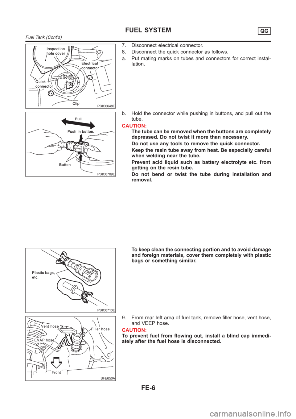
7. Disconnect electrical connector.
8. Disconnect the quick connector as follows.
a. Put mating marks on tubes and connectors for correct instal-
lation.
PBIC0709E
b. Hold the connector while pushing in buttons, and pull out the
tube.
CAUTION:
The tube can be removed when the buttons are completely
depressed. Do not twist it more than necessary.
Do not use any tools to remove the quick connector.
Keep the resin tube away from heat. Be especially careful
when welding near the tube.
Prevent acid liquid such as battery electrolyte etc. from
getting on the resin tube.
Do not bend or twist the tube during installation and
removal.
PBIC0713E
To keep clean the connecting portion and to avoid damage
and foreign materials, cover them completely with plastic
bags or something similar.
SFE650A
9. From rear left area of fuel tank, remove filler hose, vent hose,
and VEEP hose.
CAUTION:
To prevent fuel from flowing out, install a blind cap immedi-
ately after the fuel hose is disconnected.
FUEL SYSTEMQG
Fuel Tank (Cont’d)
FE-6
Page 2453 of 3189

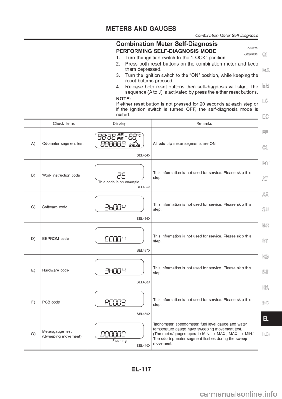
Combination Meter Self-DiagnosisNJEL0447PERFORMING SELF-DIAGNOSIS MODENJEL0447S011. Turn the ignition switch to the “LOCK” position.
2. Press both reset buttons on the combination meter and keep
them depressed.
3. Turn the ignition switch to the “ON” position, while keeping the
reset buttons pressed.
4. Release both reset buttons then self-diagnosis will start. The
sequence (A to J) is activated by press the either reset buttons.
NOTE:
If either reset button is not pressed for 20 seconds at each step or
if the ignition switch is turned OFF, the self-diagnosis mode is
exited.
Check items Display Remarks
A) Odometer segment test
SEL434X
All odo trip meter segments are ON.
B) Work instruction code
SEL435X
This information is not used for service. Please skip this
step.
C) Software code
SEL436X
This information is not used for service. Please skip this
step.
D) EEPROM code
SEL437X
This information is not used for service. Please skip this
step.
E) Hardware code
SEL438X
This information is not used for service. Please skip this
step.
F) PCB code
SEL439X
This information is not used for service. Please skip this
step.
G)Meter/gauge test
(Sweeping movement)
SEL440X
Tachometer, speedometer, fuel level gauge and water
temperature gauge have sweeping movement test.
(The meter/gauges operate MIN.,MAX., MAX.,MIN.)
The odo trip meter segment flushes during the sweep
movement.
GI
MA
EM
LC
EC
FE
CL
MT
AT
AX
SU
BR
ST
RS
BT
HA
SC
IDX
METERS AND GAUGES
Combination Meter Self-Diagnosis
EL-117
Page 2455 of 3189

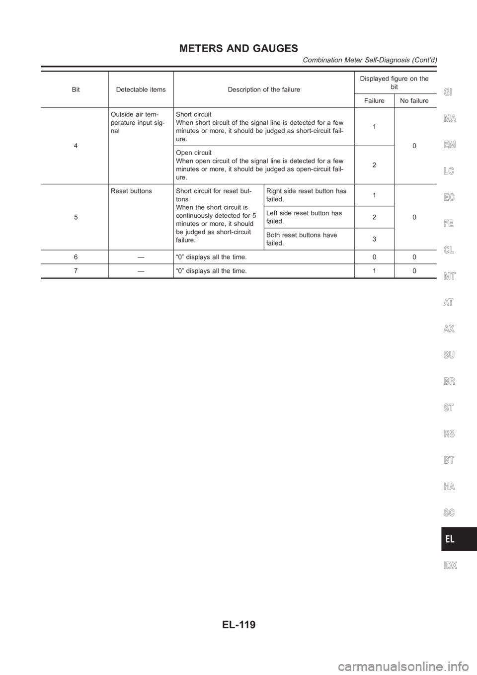
Bit Detectable items Description of the failureDisplayed figure on the
bit
Failure No failure
4Outside air tem-
perature input sig-
nalShort circuit
When short circuit of the signal line is detected for a few
minutes or more, it should be judged as short-circuit fail-
ure.1
0
Open circuit
When open circuit of the signal line is detected for a few
minutes or more, it should be judged as open-circuit fail-
ure.2
5Reset buttons Short circuit for reset but-
tons
When the short circuit is
continuously detected for 5
minutes or more, it should
be judged as short-circuit
failure.Right side reset button has
failed.1
0 Left side reset button has
failed.2
Both reset buttons have
failed.3
6 — “0” displays all the time. 0 0
7 — “0” displays all the time. 1 0GI
MA
EM
LC
EC
FE
CL
MT
AT
AX
SU
BR
ST
RS
BT
HA
SC
IDX
METERS AND GAUGES
Combination Meter Self-Diagnosis (Cont’d)
EL-119