check engine light NISSAN ALMERA N16 2003 Electronic Repair Manual
[x] Cancel search | Manufacturer: NISSAN, Model Year: 2003, Model line: ALMERA N16, Model: NISSAN ALMERA N16 2003Pages: 3189, PDF Size: 54.76 MB
Page 25 of 3189
Incident Simulation TestsNJGI0005S02INTRODUCTIONNJGI0005S0201Sometimes the symptom is not present when the vehicle is brought
in for service. If possible, re-create the conditions present at the
time of the incident. Doing so may help avoid a No Trouble Found
Diagnoses. The following section illustrates ways to simulate the
conditions/environment under which the owner experiences an
electrical incident.
The section is broken into the six following topics:
Vehicle vibration
Heat sensitive
Freezing
Water intrusion
Electrical load
Cold or hot start up
Get a thorough description of the incident from the customer. It is
important for simulating the conditions of the problem.
VEHICLE VIBRATIONNJGI0005S0202The problem may occur or become worse while driving on a rough
road or when engine is vibrating (idle with A/C on). In such a case,
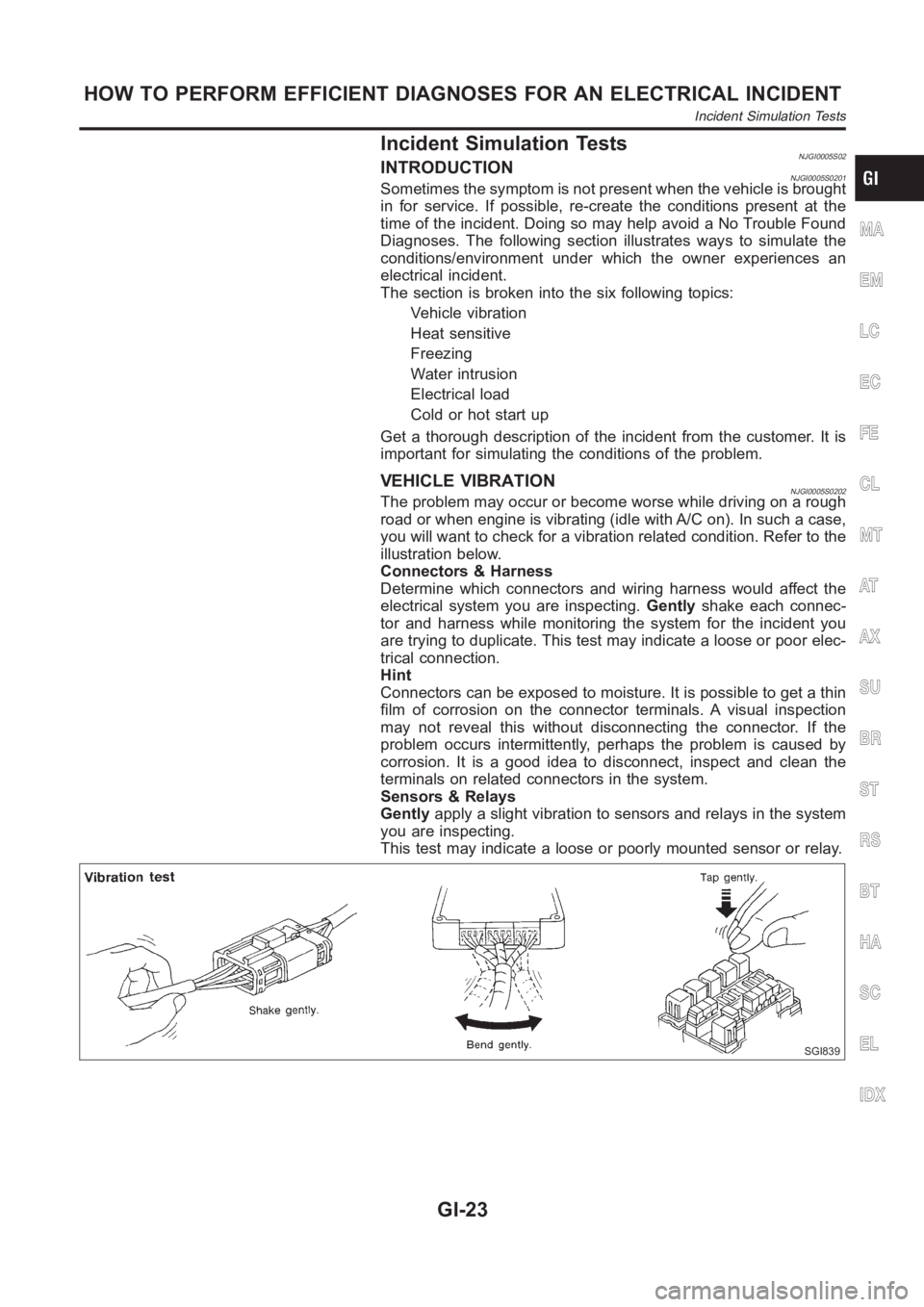
you will want to check for a vibration related condition. Refer to the
illustration below.
Connectors & Harness
Determine which connectors and wiring harness would affect the
electrical system you are inspecting.Gentlyshake each connec-
tor and harness while monitoring the system for the incident you
are trying to duplicate. This test may indicate a loose or poor elec-
trical connection.
Hint
Connectors can be exposed to moisture. It is possible to get a thin
film of corrosion on the connector terminals. A visual inspection
may not reveal this without disconnecting the connector. If the
problem occurs intermittently, perhaps the problem is caused by
corrosion. It is a good idea to disconnect, inspect and clean the
terminals on related connectors in the system.
Sensors & Relays
Gentlyapply a slight vibration to sensors and relays in the system
you are inspecting.
This test may indicate a loose or poorly mounted sensor or relay.
SGI839
MA
EM
LC
EC
FE
CL
MT
AT
AX
SU
BR
ST
RS
BT
HA
SC
EL
IDX
HOW TO PERFORM EFFICIENT DIAGNOSES FOR AN ELECTRICAL INCIDENT
Incident Simulation Tests
GI-23
Page 55 of 3189
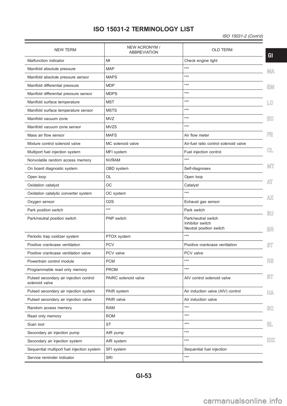
NEW TERMNEW ACRONYM /
ABBREVIATIONOLD TERM
Malfunction indicator MI Check engine light
Manifold absolute pressure MAP ***
Manifold absolute pressure sensor MAPS ***
Manifold differential pressure MDP ***
Manifold differential pressure sensor MDPS ***
Manifold surface temperature MST ***
Manifold surface temperature sensor MSTS ***
Manifold vacuum zone MVZ ***
Manifold vacuum zone sensor MVZS ***
Mass air flow sensor MAFS Air flow meter
Mixture control solenoid valve MC solenoid valve Air-fuel ratio control solenoid valve
Multiport fuel injection system MFI system Fuel injection control
Nonvolatile random access memory NVRAM ***
On board diagnostic system OBD system Self-diagnoses
Open loop OL Open loop
Oxidation catalyst OC Catalyst
Oxidation catalytic converter system OC system ***
Oxygen sensor O2S Exhaust gas sensor
Park position switch *** Park switch
Park/neutral position switch PNP switch Park/neutral switch
Inhibitor switch
Neutral position switch
Periodic trap oxidizer system PTOX system ***
Positive crankcase ventilation PCV Positive crankcase ventilation
Positive crankcase ventilation valve PCV valve PCV valve
Powertrain control module PCM ***
Programmable read only memory PROM ***
Pulsed secondary air injection control
solenoid valvePAIRC solenoid valve AIV control solenoid valve
Pulsed secondary air injection system PAIR system Air induction valve (AIV) control
Pulsed secondary air injection valve PAIR valve Air induction valve
Random access memory RAM ***
Read only memory ROM ***
Scan tool ST ***
Secondary air injection pump AIR pump ***
Secondary air injection system AIR system ***
Sequential multiport fuel injection system SFI system Sequential fuel injection
Service reminder indicator SRI ***
MA
EM
LC
EC
FE
CL
MT
AT
AX
SU
BR
ST
RS
BT
HA
SC
EL
IDX
ISO 15031-2 TERMINOLOGY LIST
ISO 15031-2 (Cont’d)
GI-53
Page 58 of 3189
NJMA0036
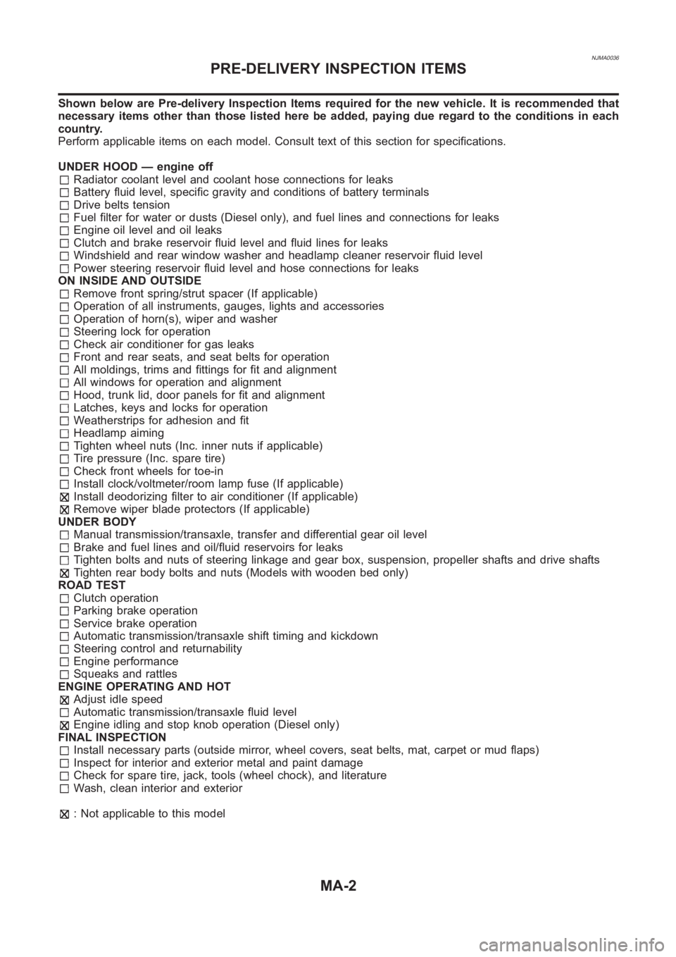
Shown below are Pre-delivery Inspection Items required for the new vehicle. It is recommended that
necessary items other than those listed here be added, paying due regard tothe conditions in each
country.
Perform applicable items on each model. Consult text of this section for specifications.
UNDER HOOD — engine off
Radiator coolant level and coolant hose connections for leaks
Battery fluid level, specific gravity and conditions of battery terminals
Drive belts tension
Fuel filter for water or dusts (Diesel only), and fuel lines and connections for leaks
Engine oil level and oil leaks
Clutch and brake reservoir fluid level and fluid lines for leaks
Windshield and rear window washer and headlamp cleaner reservoir fluid level
Power steering reservoir fluid level and hose connections for leaks
ON INSIDE AND OUTSIDE
Remove front spring/strut spacer (If applicable)
Operation of all instruments, gauges, lights and accessories
Operation of horn(s), wiper and washer
Steering lock for operation
Check air conditioner for gas leaks
Front and rear seats, and seat belts for operation
All moldings, trims and fittings for fit and alignment
All windows for operation and alignment
Hood, trunk lid, door panels for fit and alignment
Latches, keys and locks for operation
Weatherstrips for adhesion and fit
Headlamp aiming
Tighten wheel nuts (Inc. inner nuts if applicable)
Tire pressure (Inc. spare tire)
Check front wheels for toe-in
Install clock/voltmeter/room lamp fuse (If applicable)
Install deodorizing filter to air conditioner (If applicable)
Remove wiper blade protectors (If applicable)
UNDER BODY
Manual transmission/transaxle, transfer and differential gear oil level
Brake and fuel lines and oil/fluid reservoirs for leaks
Tighten bolts and nuts of steering linkage and gear box, suspension, propeller shafts and drive shafts
Tighten rear body bolts and nuts (Models with wooden bed only)
ROAD TEST
Clutch operation
Parking brake operation
Service brake operation
Automatic transmission/transaxle shift timing and kickdown
Steering control and returnability
Engine performance
Squeaks and rattles
ENGINE OPERATING AND HOT
Adjust idle speed
Automatic transmission/transaxle fluid level
Engine idling and stop knob operation (Diesel only)
FINAL INSPECTION
Install necessary parts (outside mirror, wheel covers, seat belts, mat, carpet or mud flaps)
Inspect for interior and exterior metal and paint damage
Check for spare tire, jack, tools (wheel chock), and literature
Wash, clean interior and exterior
: Not applicable to this model
PRE-DELIVERY INSPECTION ITEMS
MA-2
Page 140 of 3189
![NISSAN ALMERA N16 2003 Electronic Repair Manual EM-62
[QG]
CYLINDER HEAD
8. Install valve collet.
●Compress valve spring with valve spring compressor (special
service tool). Install valve collet with magnet hand.
●Tap stem edge lightly with pla NISSAN ALMERA N16 2003 Electronic Repair Manual EM-62
[QG]
CYLINDER HEAD
8. Install valve collet.
●Compress valve spring with valve spring compressor (special
service tool). Install valve collet with magnet hand.
●Tap stem edge lightly with pla](/img/5/57350/w960_57350-139.png)
EM-62
[QG]
CYLINDER HEAD
8. Install valve collet.
●Compress valve spring with valve spring compressor (special
service tool). Install valve collet with magnet hand.
●Tap stem edge lightly with plastic hammer after installation to
check its installed condition.
9. Install adjusting shim (if so equipped) and valve lifter.
10. Install engine coolant temperature sensor.
●Apply Genuine Liquid Gasket or equivalent to the thread.
11. Install spark plug tube.
●Press-fit spark plug tube following procedure below.
a. Remove old liquid gasket adhering to cylinder-head mounting
hole.
b. Apply liquid gasket to area within approximately 15 mm (0.59 in)
from edge of spark plug tube press-fit side.
●Use Genuine Liquid Gasket or equivalent.
c. Using a drift, press-fit spark plug tube so that its height “H” is as
specified in the figure.
CAUTION:
●When press-fitting, take care not to deform spark plug tube.
●After press-fitting, wipe off liquid gasket protruding onto cylinder-head upper face.
12. Install spark plug with spark plug wrench (commercial service tool).
Inspection After DisassemblyEBS00LQK
CYLINDER HEAD DISTORTION
1. Wipe off oil and remove water scale (like deposit), gasket,
sealer, carbon, etc with scraper.
CAUTION:
Use utmost care not to allow gasket debris to enter pas-
sages for oil or water.
2. At each of several locations on bottom surface of cylinder head,
measure distortion in six directions.
VALVE DIMENSIONS
Check dimensions of each valve. For dimensions, refer to EM-94,
"VA LV E" .
PBIC1016E
Standard press-fit height “H” :
: 41.0 - 42.0 mm (1.61 - 1.65 in)KBIA1248E
Limit : 0.1 mm (0.004 in)
PBIC0075E
SEM188A
Page 215 of 3189
JEM143G
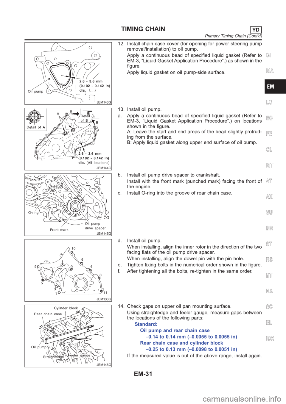
12. Install chain case cover (for opening for power steering pump
removal/installation) to oil pump.
Apply a continuous bead of specified liquid gasket (Refer to
EM-3, “Liquid Gasket Application Procedure”.) as shown in the
figure.
Apply liquid gasket on oil pump-side surface.
JEM144G
13. Install oil pump.
a. Apply a continuous bead of specified liquid gasket (Refer to
EM-3, “Liquid Gasket Application Procedure”.) on locations
shown in the figure.
A: Leave the start and end areas of the bead slightly protrud-
ing from the surface.
B: Apply liquid gasket along upper end surface of oil pump.
JEM145G
b. Install oil pump drive spacer to crankshaft.
Install with the front mark (punched mark) facing the front of
the engine.
c. Install O-ring into the groove of rear chain case.
JEM133G
d. Install oil pump.
When installing, align the inner rotor in the direction of the two
facing flats of the oil pump drive spacer.
When installing, align the dowel pin with the pin hole.
e. Tighten fixing bolts in the numerical order shown in the figure.
f. After tightening all the bolts, re-tighten in the same order.
JEM146G
14. Check gaps on upper oil pan mounting surface.
Using straightedge and feeler gauge, measure gaps between
the locations of the following parts:
Standard:
Oil pump and rear chain case
–0.14 to 0.14 mm (–0.0055 to 0.0055 in)
Rear chain case and cylinder block
–0.25 to 0.13 mm (–0.0098 to 0.0051 in)
If the measured value is out of the above range, install again.
GI
MA
LC
EC
FE
CL
MT
AT
AX
SU
BR
ST
RS
BT
HA
SC
EL
IDX
TIMING CHAINYD
Primary Timing Chain (Cont’d)
EM-31
Page 291 of 3189
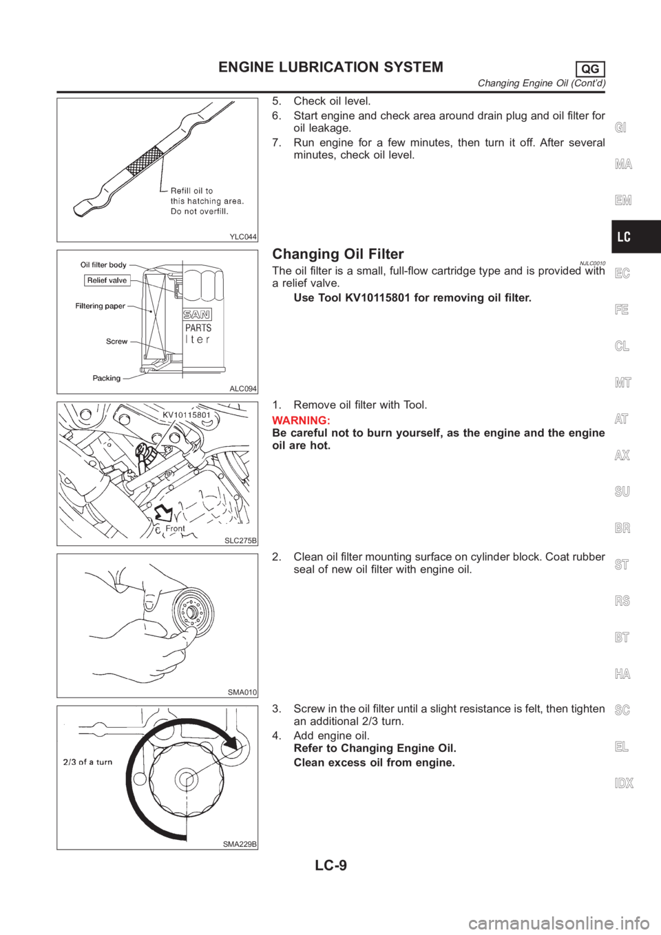
YLC044
5. Check oil level.
6. Start engine and check area around drain plug and oil filter for
oil leakage.
7. Run engine for a few minutes, then turn it off. After several
minutes, check oil level.
ALC094
Changing Oil FilterNJLC0010The oil filter is a small, full-flow cartridge type and is provided with
a relief valve.
Use Tool KV10115801 for removing oil filter.
SLC275B
1. Remove oil filter with Tool.
WARNING:
Be careful not to burn yourself, as the engine and the engine
oil are hot.
SMA010
2. Clean oil filter mounting surface on cylinder block. Coat rubber
seal of new oil filter with engine oil.
SMA229B
3. Screw in the oil filter until a slight resistance is felt, then tighten
an additional 2/3 turn.
4. Add engine oil.
Refer to Changing Engine Oil.
Clean excess oil from engine.
GI
MA
EM
EC
FE
CL
MT
AT
AX
SU
BR
ST
RS
BT
HA
SC
EL
IDX
ENGINE LUBRICATION SYSTEMQG
Changing Engine Oil (Cont’d)
LC-9
Page 340 of 3189
![NISSAN ALMERA N16 2003 Electronic Repair Manual EC-10
[QG (WITH EURO-OBD)]
INDEX FOR DTC
[QG (WITH EURO-OBD)]INDEX FOR DTCPFP:00024
Alphabetical IndexEBS00K2T
Check if the vehicle is a model with Euro-OBD (E-OBD) system or not by the “Type approv NISSAN ALMERA N16 2003 Electronic Repair Manual EC-10
[QG (WITH EURO-OBD)]
INDEX FOR DTC
[QG (WITH EURO-OBD)]INDEX FOR DTCPFP:00024
Alphabetical IndexEBS00K2T
Check if the vehicle is a model with Euro-OBD (E-OBD) system or not by the “Type approv](/img/5/57350/w960_57350-339.png)
EC-10
[QG (WITH EURO-OBD)]
INDEX FOR DTC
[QG (WITH EURO-OBD)]INDEX FOR DTCPFP:00024
Alphabetical IndexEBS00K2T
Check if the vehicle is a model with Euro-OBD (E-OBD) system or not by the “Type approval number” on the
identification plate. Refer to GI-39.
NOTE:
If DTC U1000 or U1001 is displayed with other DTC, first perform the trouble diagnosis for DTC U1000,
U1001. Refer to EC-116, "
DTC U1000, U1001 CAN COMMUNICATION LINE" .
×: Applicable –: Not applicable
Items
(CONSULT-II screen terms)DTC*
1
TripMI lighting
upReference page
CONSULT-II
GST*
2ECM*3
A/T 1ST GR FNCTN P0731 0731 2×AT-133
A/T 2ND GR FNCTN P0732 0732 2×AT-139
A/T 3RD GR FNCTN P0733 0733 2×AT-145
A/T 4TH GR FNCTN P0734 0734 2×AT-151
APP SEN 1/CIRC P0227 0227 1×EC-218
APP SEN 1/CIRC P0228 0228 1×EC-218
APP SEN 2/CIRC P1227 1227 1×EC-345
APP SEN 2/CIRC P1228 1228 1×EC-345
APP SENSOR P0226 0226 1×EC-211
ATF TEMP SEN/CIRC P0710 0710 2×AT- 11 7
BRAKE SW/CIRCUIT P1805 1805 2 –EC-360
CAN COMM CIRCUIT U1000
1000*51×EC-116
CAN COMM CIRCUIT U1001
1001*52–EC-116
CKP SEN/CIRCUIT P0335 0335 2×EC-234
CMP SEN/CIRC-B1 P0340 0340 2×EC-240
CTP LEARNING P1225 1225 2 –EC-341
CTP LEARNING P1226 1226 2 –EC-343
CYL 1 MISFIRE P0301 0301 2×EC-225
CYL 2 MISFIRE P0302 0302 2×EC-225
CYL 3 MISFIRE P0303 0303 2×EC-225
CYL 4 MISFIRE P0304 0304 2×EC-225
ECM P0605 0605 1 or 2× or –EC-265
ECM BACK UP/CIRC P1065 1065 2×EC-268
ECT SEN/CIRCUIT P0117 0117 1×EC-144
ECT SEN/CIRCUIT P0118 0118 1×EC-144
ENG OVER TEMP P1217 1217 1×EC-324
ENGINE SPEED SIG P0725 0725 1×AT-129
ETC ACTR P1121 1121 1 or 2×EC-276
ETC FUNCTION/CIRC P1122 1122 1×EC-278
ETC MOT P1128 1128 1×EC-291
ETC MOT PWR P1124 1124 1×EC-285
ETC MOT PWR P1126 1126 1×EC-285
FUEL SYS-LEAN-B1 P0171 0171 2×EC-186
FUEL SYS-RICH-B1 P0172 0172 2×EC-193
HO2S1 (B1) P0132 0132 2×EC-149
Page 342 of 3189
![NISSAN ALMERA N16 2003 Electronic Repair Manual EC-12
[QG (WITH EURO-OBD)]
INDEX FOR DTC
*1: 1st trip DTC No. is the same as DTC No.
*2: These numbers are prescribed by ISO 15031-5.
*3: In Diagnostic Test Mode II (Self-diagnostic results), these nu NISSAN ALMERA N16 2003 Electronic Repair Manual EC-12
[QG (WITH EURO-OBD)]
INDEX FOR DTC
*1: 1st trip DTC No. is the same as DTC No.
*2: These numbers are prescribed by ISO 15031-5.
*3: In Diagnostic Test Mode II (Self-diagnostic results), these nu](/img/5/57350/w960_57350-341.png)
EC-12
[QG (WITH EURO-OBD)]
INDEX FOR DTC
*1: 1st trip DTC No. is the same as DTC No.
*2: These numbers are prescribed by ISO 15031-5.
*3: In Diagnostic Test Mode II (Self-diagnostic results), these numbers are controlled by NISSAN.
*4: When engine is running.
*5: The troubleshooting for this DTC needs CONSULT-II.
*6: When the fail-safe operations for both self-diagnoses occur, the MI illuminates.
DTC No. IndexEBS00K2U
Check if the vehicle is a model with Euro-OBD (E-OBD) system or not by the “Type approval number” on the
identification plate. Refer to GI-39.
NOTE:
If DTC U1000 or U1001 is displayed with other DTC, first perform the trouble diagnosis for DTC U1000,
U1001. Refer to EC-116, "
DTC U1000, U1001 CAN COMMUNICATION LINE" .
×: Applicable –: Not applicable TW CATALYST SYS-B1 P0420 0420 2×EC-246
VEH SPD SEN/CIR AT*6P0720 0720 2×AT-123
VEH SPEED SEN/CIRC P0500 0500 2×EC-257
Items
(CONSULT-II screen terms)DTC*
1
TripMI lighting
upReference page
CONSULT-II
GST*
2ECM*3
DTC*1
Items
(CONSULT-II screen terms)TripMI lighting
upReference page
CONSULT-II
GST*
2ECM*3
No DTC
Flashing*4NO DTC IS DETECTED.
FURTHER TESTING
MAY BE REQUIRED.–
Flashing*4EC-50
U1000
1000*5CAN COMM CIRCUIT 1×EC-116
U1001
1001*5CAN COMM CIRCUIT 2 –EC-116
P0000 0000NO DTC IS DETECTED.
FURTHER TESTING
MAY BE REQUIRED.––—
P0011 0011 INT/V TIM CONT-B1 2 –EC-119
P0031 0031 HO2S1 HTR (B1) 2×EC-122
P0032 0032 HO2S1 HTR (B1) 2×EC-122
P0037 0037 HO2S2 HTR (B1) 2×EC-128
P0038 0038 HO2S2 HTR (B1) 2×EC-128
P0102 0102 MAF SEN/CIRCUIT 1×EC-134
P0103 0103 MAF SEN/CIRCUIT 1×EC-134
P0112 0112 IAT SEN/CIRCUIT 2×EC-140
P0113 0113 IAT SEN/CIRCUIT 2×EC-140
P0117 0117 ECT SEN/CIRCUIT 1×EC-144
P0118 0118 ECT SEN/CIRCUIT 1×EC-144
P0132 0132 HO2S1 (B1) 2×EC-149
P0133 0133 HO2S1 (B1) 2×EC-155
P0134 0134 HO2S1 (B1) 2×EC-165
P0138 0138 HO2S2 (B1) 2×EC-172
P0139 0139 HO2S2 (B1) 2×EC-178
P0171 0171 FUEL SYS-LEAN-B1 2×EC-186
P0172 0172 FUEL SYS-RICH-B1 2×EC-193
P0221 0221 TP SENSOR 1×EC-199
Page 361 of 3189
![NISSAN ALMERA N16 2003 Electronic Repair Manual BASIC SERVICE PROCEDURE
EC-31
[QG (WITH EURO-OBD)]
C
D
E
F
G
H
I
J
K
L
MA
EC
2. Connect No. 1 ignition coil and No. 1 spark plug with suitable
high-tension wire as shown, and attach timing NISSAN ALMERA N16 2003 Electronic Repair Manual BASIC SERVICE PROCEDURE
EC-31
[QG (WITH EURO-OBD)]
C
D
E
F
G
H
I
J
K
L
MA
EC
2. Connect No. 1 ignition coil and No. 1 spark plug with suitable
high-tension wire as shown, and attach timing](/img/5/57350/w960_57350-360.png)
BASIC SERVICE PROCEDURE
EC-31
[QG (WITH EURO-OBD)]
C
D
E
F
G
H
I
J
K
L
MA
EC
2. Connect No. 1 ignition coil and No. 1 spark plug with suitable
high-tension wire as shown, and attach timing light clamp to this
wire.
3. Check ignition timing.
Accelerator Pedal Released Position LearningEBS00K3B
DESCRIPTION
“Accelerator Pedal Released Position Learning” is an operation to learn the fully released position of the accel-
erator pedal by monitoring the accelerator pedal position sensor output signal. It must be performed each time
harness connector of accelerator pedal position sensor or ECM is disconnected.
OPERATION PROCEDURE
1. Make sure that accelerator pedal is fully released.
2. Turn ignition switch “ON” and wait at least 2 seconds.
3. Turn ignition switch “OFF” wait at least 10 seconds.
4. Turn ignition switch “ON” and wait at least 2 seconds.
5. Turn ignition switch “OFF” wait at least 10 seconds.
Throttle Valve Closed Position LearningEBS00K3C
DESCRIPTION
“Throttle Valve Closed Position Learning” is an operation to learn the fully closed position of the throttle valve
by monitoring the throttle position sensor output signal. It must be performed each time harness connector of
electric throttle control actuator or ECM is disconnected.
OPERATION PROCEDURE
1. Make sure that accelerator pedal is fully released.
2. Turn ignition switch “ON”.
3. Turn ignition switch “OFF” wait at least 10 seconds.
Make sure that throttle valve moves during above 10 seconds by confirming the operating sound.
Idle Air Volume LearningEBS00K3D
DESCRIPTION
“Idle Air Volume Learning” is an operation to learn the idle air volume that keeps each engine within the spe-
cific range. It must be performed under any of the following conditions:
●Each time electric throttle control actuator or ECM is replaced.
●Idle speed or ignition timing is out of specification.
MBIB0049E
SEF166Y
Page 362 of 3189
![NISSAN ALMERA N16 2003 Electronic Repair Manual EC-32
[QG (WITH EURO-OBD)]
BASIC SERVICE PROCEDURE
PREPARATION
Before performing “Idle Air Volume Learning”, make sure that all of the following conditions are satisfied.
Learning will be cancelle NISSAN ALMERA N16 2003 Electronic Repair Manual EC-32
[QG (WITH EURO-OBD)]
BASIC SERVICE PROCEDURE
PREPARATION
Before performing “Idle Air Volume Learning”, make sure that all of the following conditions are satisfied.
Learning will be cancelle](/img/5/57350/w960_57350-361.png)
EC-32
[QG (WITH EURO-OBD)]
BASIC SERVICE PROCEDURE
PREPARATION
Before performing “Idle Air Volume Learning”, make sure that all of the following conditions are satisfied.
Learning will be cancelled if any of the following conditions are missed for even a moment.
●Battery voltage: More than 12.9V (At idle)
●Engine coolant temperature: 70 - 95°C (158 - 203°F)
●PNP switch: ON
●Electric load switch: OFF
(Air conditioner, headlamp, rear window defogger)
On vehicles equipped with daytime light systems, set lighting switch to the 1st position to light
only small lamps.
●Steering wheel: Neutral (Straight-ahead position)
●Vehicle speed: Stopped
●Transmission: Warmed-up
For A/T models with CONSULT-II, drive vehicle until “FLUID TEMP SE” in “DATA MONITOR” mode of “A/
T” system indicates less than 0.9V.
For A/T models without CONSULT-II and M/T models, drive vehicle for 10 minutes.
OPERATION PROCEDURE
With CONSULT-II
1. Perform EC-31, "Accelerator Pedal Released Position Learning" .
2. Perform EC-31, "
Throttle Valve Closed Position Learning" .
3. Start engine and warm it up to normal operating temperature.
4. Check that all items listed under the topic “PREPARATION” (previously mentioned) are in good order.
5. Select “IDLE AIR VOL LEARN” in “WORK SUPPORT” mode.
6. Touch “START” and wait 20 seconds.
SEF217Z
SEF454Y