keyless NISSAN ALMERA N16 2003 Electronic Repair Manual
[x] Cancel search | Manufacturer: NISSAN, Model Year: 2003, Model line: ALMERA N16, Model: NISSAN ALMERA N16 2003Pages: 3189, PDF Size: 54.76 MB
Page 2691 of 3189

SIIA1645E
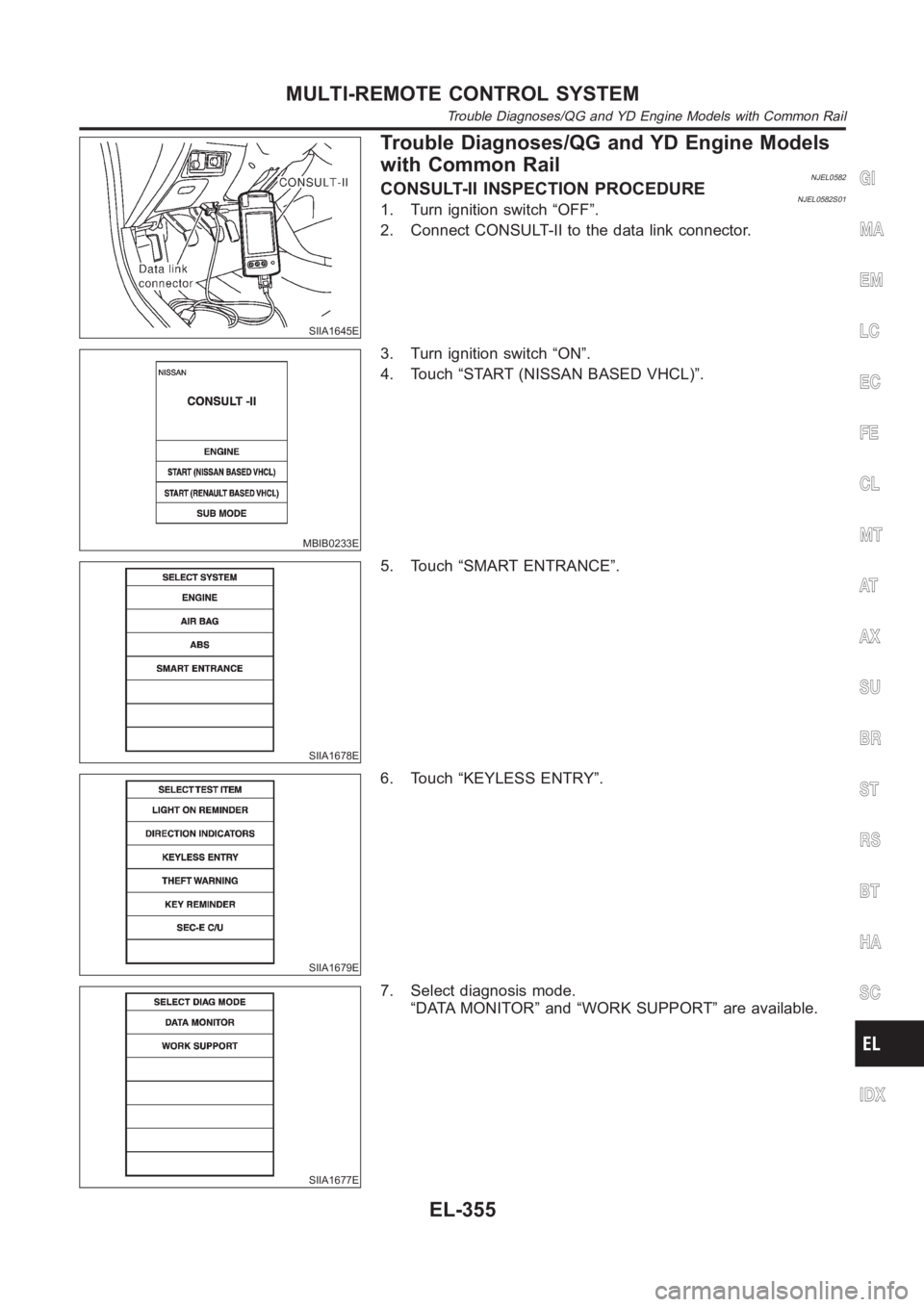
Trouble Diagnoses/QG and YD Engine Models
with Common Rail
NJEL0582CONSULT-II INSPECTION PROCEDURENJEL0582S011. Turn ignition switch “OFF”.
2. Connect CONSULT-II to the data link connector.
MBIB0233E
3. Turn ignition switch “ON”.
4. Touch “START (NISSAN BASED VHCL)”.
SIIA1678E
5. Touch “SMART ENTRANCE”.
SIIA1679E
6. Touch “KEYLESS ENTRY”.
SIIA1677E
7. Select diagnosis mode.
“DATA MONITOR” and “WORK SUPPORT” are available.
GI
MA
EM
LC
EC
FE
CL
MT
AT
AX
SU
BR
ST
RS
BT
HA
SC
IDX
MULTI-REMOTE CONTROL SYSTEM
Trouble Diagnoses/QG and YD Engine Models with Common Rail
EL-355
Page 2692 of 3189
![NISSAN ALMERA N16 2003 Electronic Repair Manual CONSULT-II APPLICATION ITEMSNJEL0582S02DATA MONITOR
Monitored Item Description
IGNITION SW Indicates [ON/OFF] condition of ignition switch in ON position.
TRUNK OPEN SW Indicates [ON/OFF] condition of NISSAN ALMERA N16 2003 Electronic Repair Manual CONSULT-II APPLICATION ITEMSNJEL0582S02DATA MONITOR
Monitored Item Description
IGNITION SW Indicates [ON/OFF] condition of ignition switch in ON position.
TRUNK OPEN SW Indicates [ON/OFF] condition of](/img/5/57350/w960_57350-2691.png)
CONSULT-II APPLICATION ITEMSNJEL0582S02DATA MONITOR
Monitored Item Description
IGNITION SW Indicates [ON/OFF] condition of ignition switch in ON position.
TRUNK OPEN SW Indicates [ON/OFF] condition of trunk room lamp switch (sedan) or back door switch (wagon).
RKE LOCK Indicates [ON/OFF] condition of lock signal from remote controller.
RKE UNLOCK Indicates [ON/OFF] condition of unlock signal from remote controller.
RKE SEL UNLOCK Indicates [ON/OFF] condition of select unlock signal from remote controller.
RKE TRUNK RELIndicates [ON/OFF] condition of trunk (sedan) or back door (wagon) open signal from trunk or
back door release switch.
BATTERY CHECK Indicates [OK/NG] condition of remote controller battery.
WORK SUPPORT
Test Item Description
KEYLESS CHECK It can be checked whether remote controller ID code is registered or not in this mode.
KEYLESS REGISTRATION Remote controller ID code can be registered.
KEYLESS DI FLASH This mode can be setting remote controller function.
SYMPTOM CHARTNJEL0582S03First perform the “SELF-DIAG RESULTS” in “SMART ENTRANCE”
with CONSULT-II, when perform the each trounble diagnosis. Refer
to EL-355, “CONSULT-II INSPECTION PROCEDURE”.
NOTE:
Always check remote controller battery before replacing
remote controller.
Symptom Diagnoses/service procedureReference
page
All function of multi-remote control system do not
operate.Remote controller battery check EL-357
Power supply and ground circuit for smart entrance control
unit checkEL-358
.If above systems are OK, replace smart entrance control unit. —
The new ID of remote controller cannot be
entered.Remote controller battery check EL-357
Key switch check —
Door switch check —
Power supply and ground circuit check EL-358
If above systems are OK, replace smart entrance control unit. —
Door lock or unlock does not function.If the power door lock system does not operate manually,
check power door lock system.EL-356
Remote controller battery check EL-357
If above systems are OK, replace smart entrance control unit. —
Hazard reminder does not activate properly
when pressing lock or unlock button of remote
controller.Remote controller battery check EL-357
Hazard reminder check EL-359
If above systems are OK, replace smart entrance control unit. —
MULTI-REMOTE CONTROL SYSTEM
Trouble Diagnoses/QG and YD Engine Models with Common Rail (Cont’d)
EL-356
Page 2706 of 3189

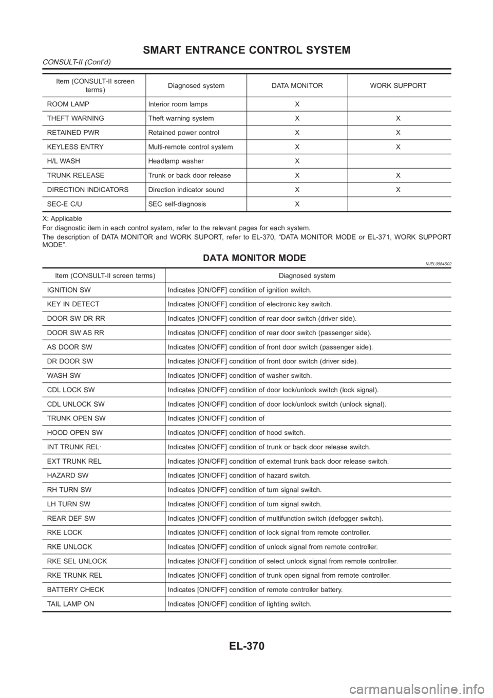
Item (CONSULT-II screen
terms)Diagnosed system DATA MONITOR WORK SUPPORT
ROOM LAMP Interior room lamps X
THEFT WARNING Theft warning system X X
RETAINED PWR Retained power control X X
KEYLESS ENTRY Multi-remote control system X X
H/L WASH Headlamp washer X
TRUNK RELEASE Trunk or back door release X X
DIRECTION INDICATORS Direction indicator sound X X
SEC-E C/U SEC self-diagnosis X
X: Applicable
For diagnostic item in each control system, refer to the relevant pages foreach system.
The description of DATA MONITOR and WORK SUPORT, refer to EL-370, “DATA MONITOR MODE or EL-371, WORK SUPPORT
MODE”.
DATA MONITOR MODENJEL0584S02
Item (CONSULT-II screen terms) Diagnosed system
IGNITION SW Indicates [ON/OFF] condition of ignition switch.
KEY IN DETECT Indicates [ON/OFF] condition of electronic key switch.
DOOR SW DR RR Indicates [ON/OFF] condition of rear door switch (driver side).
DOOR SW AS RR Indicates [ON/OFF] condition of rear door switch (passenger side).
AS DOOR SW Indicates [ON/OFF] condition of front door switch (passenger side).
DR DOOR SW Indicates [ON/OFF] condition of front door switch (driver side).
WASH SW Indicates [ON/OFF] condition of washer switch.
CDL LOCK SW Indicates [ON/OFF] condition of door lock/unlock switch (locksignal).
CDL UNLOCK SW Indicates [ON/OFF] condition of door lock/unlock switch (unlock signal).
TRUNK OPEN SW Indicates [ON/OFF] condition of
HOOD OPEN SW Indicates [ON/OFF] condition of hood switch.
INT TRUNK REL· Indicates [ON/OFF] condition of trunk or back door release switch.
EXT TRUNK REL Indicates [ON/OFF] condition of external trunk back door release switch.
HAZARD SW Indicates [ON/OFF] condition of hazard switch.
RH TURN SW Indicates [ON/OFF] condition of turn signal switch.
LH TURN SW Indicates [ON/OFF] condition of turn signal switch.
REAR DEF SW Indicates [ON/OFF] condition of multifunction switch (defogger switch).
RKE LOCK Indicates [ON/OFF] condition of lock signal from remote controller.
RKE UNLOCK Indicates [ON/OFF] condition of unlock signal from remote controller.
RKE SEL UNLOCK Indicates [ON/OFF] condition of select unlock signal from remote controller.
RKE TRUNK REL Indicates [ON/OFF] condition of trunk open signal from remote controller.
BATTERY CHECK Indicates [ON/OFF] condition of remote controller battery.
TAIL LAMP ON Indicates [ON/OFF] condition of lighting switch.
SMART ENTRANCE CONTROL SYSTEM
CONSULT-II (Cont’d)
EL-370
Page 2707 of 3189

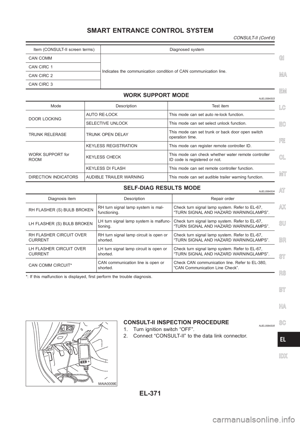
Item (CONSULT-II screen terms) Diagnosed system
CAN COMM
Indicates the communication condition of CAN communication line. CANCIRC1
CANCIRC2
CANCIRC3
WORK SUPPORT MODENJEL0584S03
Mode Description Test item
DOOR LOCKINGAUTO RE-LOCK This mode can set auto re-lock function.
SELECTIVE UNLOCK This mode can set select unlock function.
TRUNK RELERASE TRUNK OPEN DELAYThis mode can set trunk or back door open switch
operation time.
WORK SUPPORT for
ROOMKEYLESS REGISTRATION This mode can register remote controller ID.
KEYLESS CHECKThis mode can check whether water remote controller
ID code is registered or not.
KEYLESS DI FLASH This mode can set remote controller function.
DIRECTION INDICATORS AUDIBLE TRAILER WARNING This mode can set audible trailer warning function.
SELF-DIAG RESULTS MODENJEL0584S04
Diagnosis item Description Repair order
RH FLASHER (S) BULB BROKENRH turn signal lamp system is mal-
functioning.Check turn signal lamp system. Refer to EL-67,
“TURN SIGNAL AND HAZARD WARNINGLAMPS”.
LH FLASHER (S) BULB BROKENLH turn signal lamp system is malfunc-
tioning.Check turn signal lamp system. Refer to EL-67,
“TURN SIGNAL AND HAZARD WARNINGLAMPS”.
RH FLASHER CIRCUIT OVER
CURRENTRH turn signal lamp circuit is open or
shorted.Check turn signal lamp system. Refer to EL-67,
“TURN SIGNAL AND HAZARD WARNINGLAMPS”.
LH FLASHER CIRCUIT OVER
CURRENTLH turn signal lamp circuit is open or
shorted.Check turn signal lamp system. Refer to EL-67,
“TURN SIGNAL AND HAZARD WARNINGLAMPS”.
CAN COMM CIRCUIT*CAN communication line is open or
shorted.Check CAN communication line. Refer to EL-380,
“CAN Communication Line Check”.
*: If this malfunction is displayed, first perform the trouble diagnosis.
MAIA0009E
CONSULT-II INSPECTION PROCEDURENJEL0584S051. Turn ignition switch “OFF”.
2. Connect “CONSULT-II” to the data link connector.
GI
MA
EM
LC
EC
FE
CL
MT
AT
AX
SU
BR
ST
RS
BT
HA
SC
IDX
SMART ENTRANCE CONTROL SYSTEM
CONSULT-II (Cont’d)
EL-371
Page 3180 of 3189

Heated oxygen sensor 2 heater
(QG engine)................................EC-129, EC-640
Heated seat<0011001100110011001100110011001100110011001100110011001100110011001100110011001100110011001100110011001100110011001100110011001100110011001100110011001100110011001100110011001100110011001100110011001100
110028002f[-247
HEATER - Wiring diagram (manual
A/C) <0011001100110011001100110011001100110011001100110011001100110011001100110011001100110011001100110011001100110011001100110011001100110011001100110011001100110011001100110011001100110011001100110011001100
1100110011001100110011001100110011[..HA-23
Heater and cooling unit (Heater core)
(manual A/C) ...............................................HA-87
Heater and cooling unit (Heater core)........ATC-123
Heater unit (heater core) ............................ATC-130
Height (Dimensions) ........................................GI-44
HFC134a (R134a) system precaution
(manual A/C) .................................................HA-2
HFC134a (R134a) system precaution............ATC-4
HFC134a (R134a) system service pro-
cedure (manual A/C)...................................HA-77
HFC134a (R134a) system service
procedure ................................................ATC-133
HFC134a (R134a) system service tools
(manual A/C) ...............................................HA-10
HFC134a (R134a) system service tools ......ATC-11
HFC134a system service equipment
precaution (manual A/C) ...............................HA-6
HFC134a system service equipment
precaution <0011001100110011001100110011001100110011001100110011001100110011001100110011001100110011001100110011001100110011001100110011001100110011001100110011001100110011001100110011001100110011001100110011001100
110024>�TC-7
HO2S1 - Wiring diaram
(QG engine) ................EC-152, EC-159, EC-169,
EC-510, EC-516
HO2S1H - Wiring diagram (QG engine) ......EC-125
HO2S2 - Wiring diagram
(QG engine) ................EC-175, EC-182, EC-312,
EC-320, EC-522
HO2S2H - Wiring diagram (QG engine) ......EC-131
Hood<0011001100110011001100110011001100110011001100110011001100110011001100110011001100110011001100110011001100110011001100110011001100110011001100110011001100110011001100110011001100110011001100110011001100
1100110011001100110011001100110011[.......BT-7
HORN - Wiring diagram................................EL-170
Horn <0011001100110011001100110011001100110011001100110011001100110011001100110011001100110011001100110011001100110011001100110011001100110011001100110011001100110011001100110011001100110011001100110011001100
1100110011001100110011001100110011[...EL-170
How to erase DTC for OBD system
(QG engine)..................................EC-48, EC-431
How to erase DTC for OBD system
(YD engine).................................................EC-34
HSEAT - Wiring diagram ......................EL-246, 247
I
IATS - Wiring diagram (QG engine) .............EC-142
IATSEN - Wiring diagram (QG engine) ........EC-646
Identification plate............................................GI-41
Identification .....................................ATC-9, ATC-10
Idle air volume learning
(QG engine)..................................EC-31, EC-426
Idle speed (QG engine) ...................EC-65, EC-444
Idle speed (YD engine) ..................................EC-48
Ignition coil (QG engine) ................EC-366, EC-662
Ignition coil (QG engine) ................................EM-24
Ignition control system
(QG engine)................................EC-366, EC-662
Ignition timing (QG engine)..............EC-65, EC-444
IGNSYS - Wiring diagram
(QG engine)................................EC-367, EC-663
ILL - Wiring diagram .......................................EL-76
Illumination <0011001100110011001100110011001100110011001100110011001100110011001100110011001100110011001100110011001100110011001100110011001100110011001100110011001100110011001100110011001100110011001100110011001100
11[...EL-75In vehicle sensor ........ATC-103, ATC-105, ATC-117
INJECT - Wiring diagram
(QG engine)................................EC-377, EC-696
Injection nozzle (YD engine) ..........................EC-21
Injector (QG engine) ......................EC-376, EC-695
Input shaft (FF M/T).....................MT-36, 64, 93, 98
Instrument panel .............................................BT-25
INT/L - Wiring diagram..................................EL-108
Intake air temperature sensor
(QG engine)................................EC-141, EC-645
Intake door control linkage adjustment ........ATC-67
Intake door motor .........................ATC-66, ATC-122
Intake manifold (QG engine) .........................EM-16
Intake sensor ..............................ATC-109, ATC-119
Intake valve timing control
(QG engine) .................EC-120, EC-273, EC-685
Intake valve timing control solenoid
valve (QG engine) ......................EC-273, EC-685
Interior lamp on-off control........................EL-81, 83
Interior lamp <0011001100110011001100110011001100110011001100110011001100110011001100110011001100110011001100110011001100110011001100110011001100110011001100110011001100110011001100110011001100110011001100110011001100
11[.EL-80
Interior <0011001100110011001100110011001100110011001100110011001100110011001100110011001100110011001100110011001100110011001100110011001100110011001100110011001100110011001100110011001100110011001100110011001100
110011001100110011[......BT-31
ISO 15031-2 Terminology ................................GI-51
ISO 15031-5 Mode 1 - 9 (QG engine) ...........EC-36
IVC - Wiring diagram (QG engine)...............EC-274
IVC/V - Wiring diagram (QG engine) ...........EC-687
J
Jacking points ..................................................GI-46
Joint connector (J/C) ....................................Foldout
Junction box (J/B).........................................Foldout
K
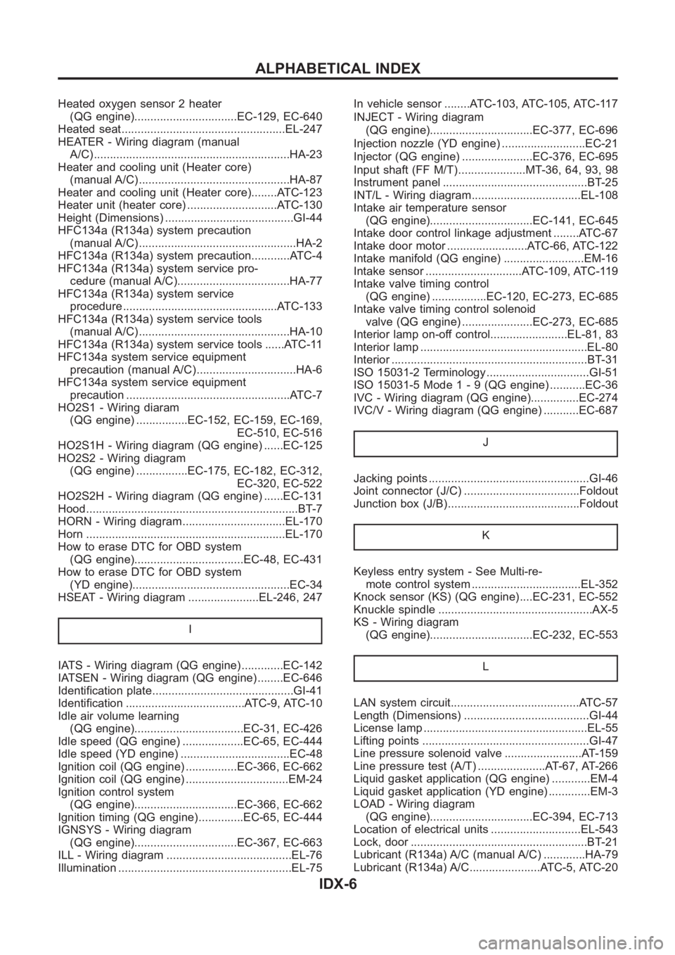
Keyless entry system - See Multi-re-
mote control system ..................................EL-352
Knock sensor (KS) (QG engine) ....EC-231, EC-552
Knuckle spindle ................................................AX-5
KS - Wiring diagram
(QG engine)................................EC-232, EC-553
L
LAN system circuit........................................ATC-57
Length (Dimensions) .......................................GI-44
License lamp <0011001100110011001100110011001100110011001100110011001100110011001100110011001100110011001100110011001100110011001100110011001100110011001100110011001100110011001100110011001100110011001100110011001100
110028[L-55
Lifting points ....................................................GI-47
Line pressure solenoid valve ........................AT-159
Line pressure test (A/T) .....................AT-67, AT-266
Liquid gasket application (QG engine) ............EM-4
Liquid gasket application (YD engine) .............EM-3
LOAD - Wiring diagram
(QG engine)................................EC-394, EC-713
Location of electrical units ............................EL-543
Lock, door <0011001100110011001100110011001100110011001100110011001100110011001100110011001100110011001100110011001100110011001100110011001100110011001100110011001100110011001100110011001100110011001100110011001100
11001100110011[.BT-21
Lubricant (R134a) A/C (manual A/C) .............HA-79
Lubricant (R134a) A/C......................ATC-5, ATC-20
ALPHABETICAL INDEX
IDX-6