service reset NISSAN ALMERA N16 2003 Electronic Repair Manual
[x] Cancel search | Manufacturer: NISSAN, Model Year: 2003, Model line: ALMERA N16, Model: NISSAN ALMERA N16 2003Pages: 3189, PDF Size: 54.76 MB
Page 427 of 3189
![NISSAN ALMERA N16 2003 Electronic Repair Manual TROUBLE DIAGNOSIS
EC-97
[QG (WITH EURO-OBD)]
C
D
E
F
G
H
I
J
K
L
MA
EC
Operation
1. “AUTO TRIG”
●While trying to detect the DTC/1st trip DTC by performing the “DTC Confirmation Procedure”, NISSAN ALMERA N16 2003 Electronic Repair Manual TROUBLE DIAGNOSIS
EC-97
[QG (WITH EURO-OBD)]
C
D
E
F
G
H
I
J
K
L
MA
EC
Operation
1. “AUTO TRIG”
●While trying to detect the DTC/1st trip DTC by performing the “DTC Confirmation Procedure”,](/img/5/57350/w960_57350-426.png)
TROUBLE DIAGNOSIS
EC-97
[QG (WITH EURO-OBD)]
C
D
E
F
G
H
I
J
K
L
MA
EC
Operation
1. “AUTO TRIG”
●While trying to detect the DTC/1st trip DTC by performing the “DTC Confirmation Procedure”, be sure
to select to “DATA MONITOR (AUTO TRIG)” mode. You can confirm the malfunction at the moment it is
detected.
●While narrowing down the possible causes, CONSULT-II should be set in “DATA MONITOR (AUTO
TRIG)” mode, especially in case the incident is intermittent.
When you are inspecting the circuit by gently shaking (or twisting) the suspicious connectors, compo-
nents and harness in the “DTC Confirmation Procedure”, the moment a malfunction is found the DTC/
1st trip DTC will be displayed. (Refer to “Incident Simulation Tests” in GI-23.)
2. “MANU TRIG”
●If the malfunction is displayed as soon as “DATA MONITOR” is selected, reset CONSULT-II to “MANU
TRIG”. By selecting “MANU TRIG” you can monitor and store the data. The data can be utilized for fur-
ther diagnosis, such as a comparison with the value for the normal operating condition.
Generic Scan Tool (GST) FunctionEBS00K3V
DESCRIPTION
Generic Scan Tool (OBDII scan tool) complying with ISO 15031-4
has 8 different functions explained below.
ISO9141 is used as the protocol.
The name “GST” or “Generic Scan Tool” is used in this service man-
ual.
PBIB0197E
SEF139P
Page 1989 of 3189
PRECAUTIONS
ATC-9
C
D
E
F
G
H
I
K
L
MA
B
AT C
SERVICE COUPLERS
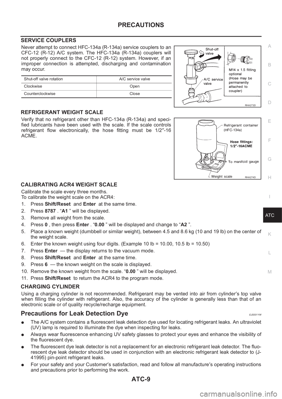
Never attempt to connect HFC-134a (R-134a) service couplers to an
CFC-12 (R-12) A/C system. The HFC-134a (R-134a) couplers will
not properly connect to the CFC-12 (R-12) system. However, if an
improper connection is attempted, discharging and contamination
may occur.
REFRIGERANT WEIGHT SCALE
Verify that no refrigerant other than HFC-134a (R-134a) and speci-
fied lubricants have been used with the scale. If the scale controls
refrigerant flow electronically, the hose fitting must be 1/2″-16
ACME.
CALIBRATING ACR4 WEIGHT SCALE
Calibrate the scale every three months.
To calibrate the weight scale on the ACR4:
1. Press Shift/Reset and Enter at the same time.
2. Press 8787 . “A1 ” will be displayed.
3. Remove all weight from the scale.
4. Press 0 , then press Enter . “0.00 ” will be displayed and change to “A2 ”.
5. Place a known weight (dumbbell or similar weight), between 4.5 and 8.6 kg (10 and 19 lb) on the center of
the weight scale.
6. Enter the known weight using four digits. (Example 10 lb = 10.00, 10.5 lb = 10.50)
7. Press Enter — the display returns to the vacuum mode.
8. Press Shift/Reset and Enter at the same time.
9. Press 6 — the known weight on the scale is displayed.
10. Remove the known weight from the scale. “0.00 ” will be displayed.
11 . P r e s s Shift/Reset to return the ACR4 to the program mode.
CHARGING CYLINDER
Using a charging cylinder is not recommended. Refrigerant may be vented into air from cylinder′s top valve
when filling the cylinder with refrigerant. Also, the accuracy of the cylinder is generally less than that of an
electronic scale or of quality recycle/recharge equipment.
Precautions for Leak Detection DyeEJS001YW
●The A/C system contains a fluorescent leak detection dye used for locating refrigerant leaks. An ultraviolet
(UV) lamp is required to illuminate the dye when inspecting for leaks.
●Always wear fluorescence enhancing UV safety glasses to protect your eyes and enhance the visibility of
the fluorescent dye.
●The fluorescent dye leak detector is not a replacement for an electronic refrigerant leak detector. The fluo-
rescent dye leak detector should be used in conjunction with an electronic refrigerant leak detector to (J-
41995) pin-point refrigerant leaks.
●For your safety and your Customer′s satisfaction, read and follow all manufacture′s operating instructions
and precautions prior to performing the work.
Shut-off valve rotation A/C service valve
Clockwise Open
Counterclockwise Close
RHA273D
RHA274D
Page 2165 of 3189
SFA975B
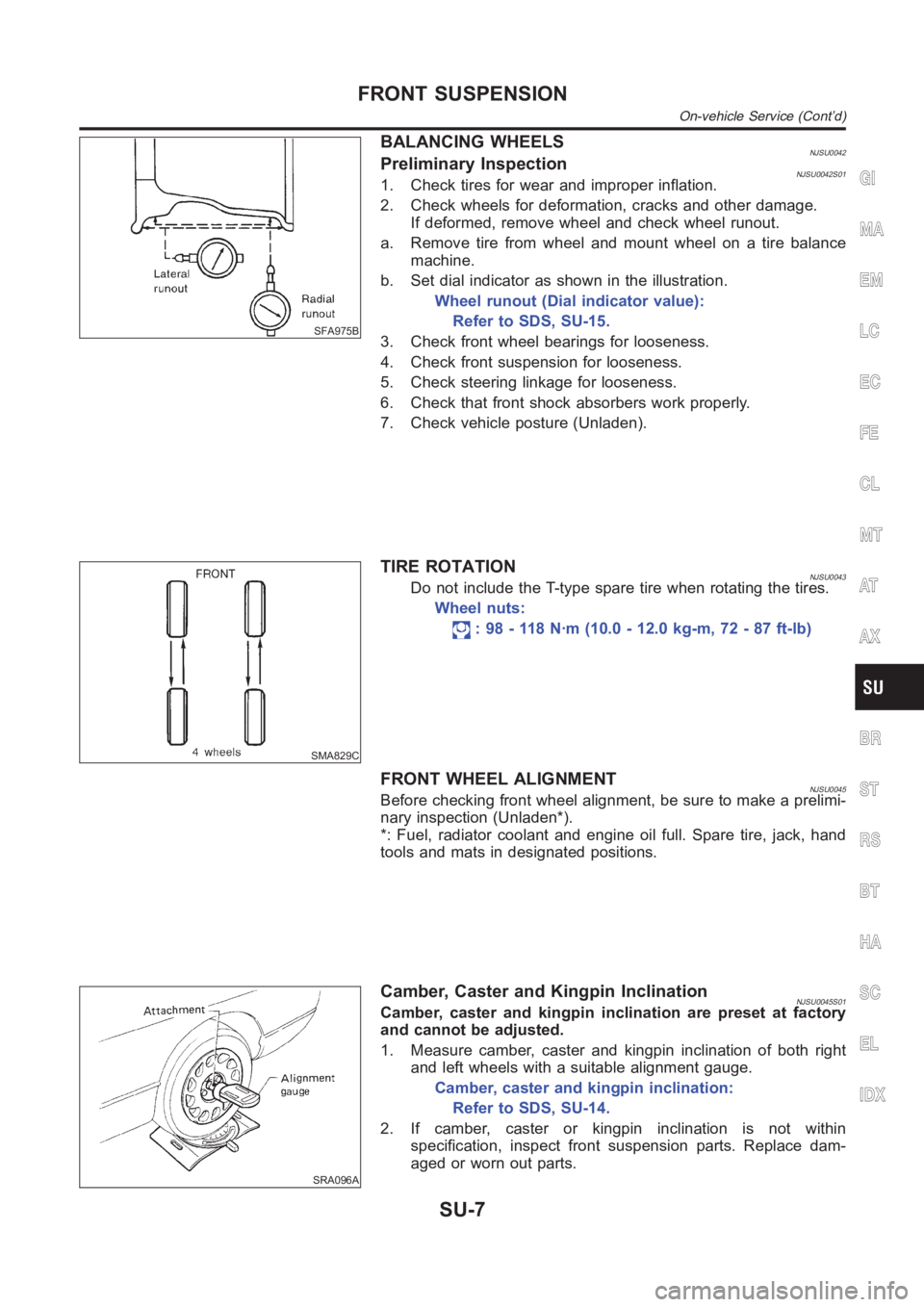
BALANCING WHEELSNJSU0042Preliminary InspectionNJSU0042S011. Check tires for wear and improper inflation.
2. Check wheels for deformation, cracks and other damage.
If deformed, remove wheel and check wheel runout.
a. Remove tire from wheel and mount wheel on a tire balance
machine.
b. Set dial indicator as shown in the illustration.
Wheel runout (Dial indicator value):
Refer to SDS, SU-15.
3. Check front wheel bearings for looseness.
4. Check front suspension for looseness.
5. Check steering linkage for looseness.
6. Check that front shock absorbers work properly.
7. Check vehicle posture (Unladen).
SMA829C
TIRE ROTATIONNJSU0043Do not include the T-type spare tire when rotating the tires.
Wheel nuts:
: 98 - 118 N·m (10.0 - 12.0 kg-m, 72 - 87 ft-lb)
FRONT WHEEL ALIGNMENTNJSU0045Before checking front wheel alignment, be sure to make a prelimi-
nary inspection (Unladen*).
*: Fuel, radiator coolant and engine oil full. Spare tire, jack, hand
tools and mats in designated positions.
SRA096A
Camber, Caster and Kingpin InclinationNJSU0045S01Camber, caster and kingpin inclination are preset at factory
and cannot be adjusted.
1. Measure camber, caster and kingpin inclination of both right
and left wheels with a suitable alignment gauge.
Camber, caster and kingpin inclination:
Refer to SDS, SU-14.
2. If camber, caster or kingpin inclination is not within
specification, inspect front suspension parts. Replace dam-
aged or worn out parts.
GI
MA
EM
LC
EC
FE
CL
MT
AT
AX
BR
ST
RS
BT
HA
SC
EL
IDX
FRONT SUSPENSION
On-vehicle Service (Cont’d)
SU-7
Page 2177 of 3189
4. Check front suspension for looseness.
5. Check steering linkage for looseness.
6. Check that front shock absorbers work properly.
7. Check vehicle posture (Unladen).
SFA948A
CamberNJSU0030S02Camber is preset at factory and cannot be adjusted.
Camber:
Refer to SDS, SU-25.
If the camber is not within specification, inspect and replace
any damaged or worn rear suspension parts.
SFA614B
SFA234AC
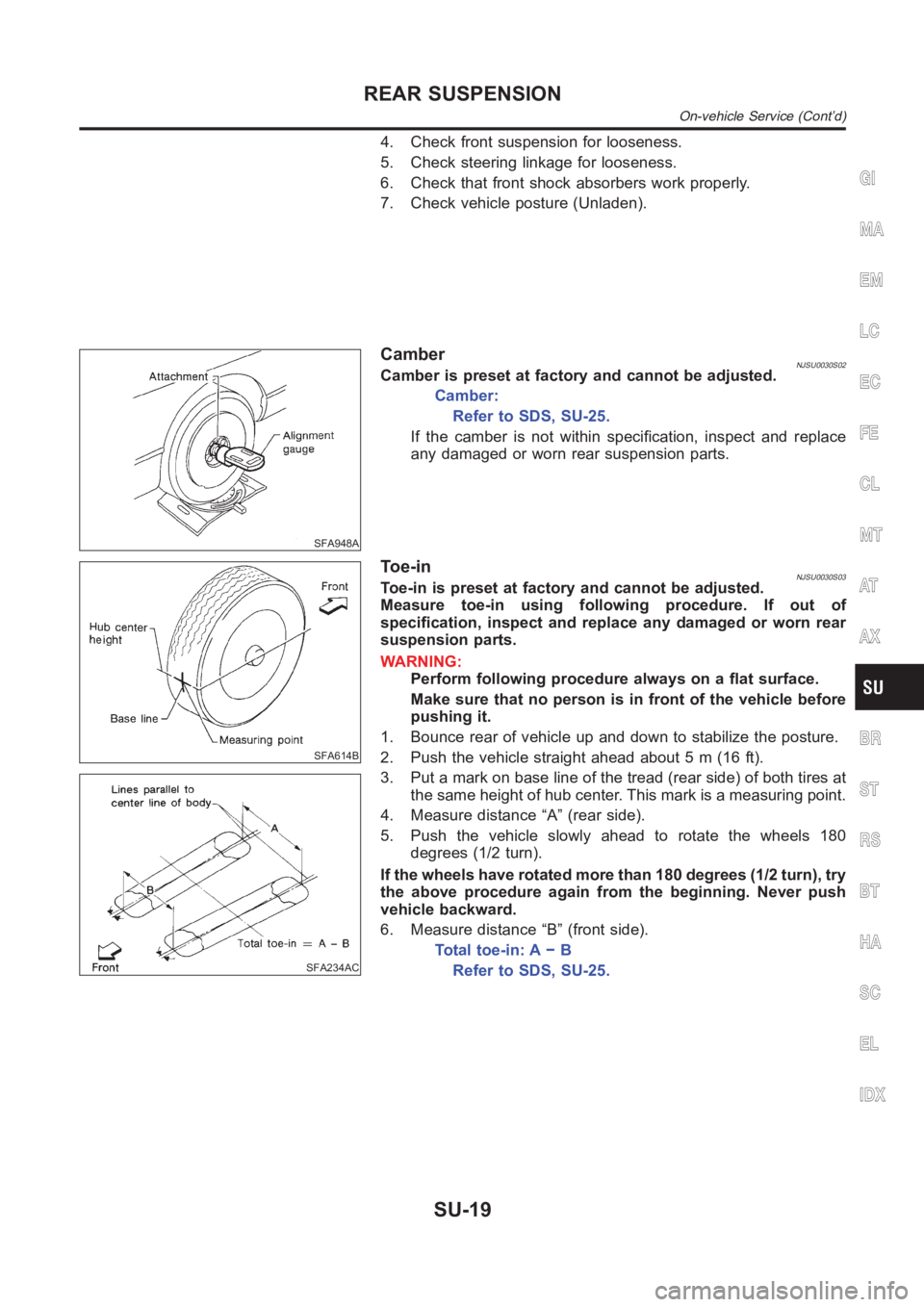
To e - i nNJSU0030S03Toe-in is preset at factory and cannot be adjusted.
Measure toe-in using following procedure. If out of
specification, inspect and replace any damaged or worn rear
suspension parts.
WARNING:
Perform following procedure always on a flat surface.
Make sure that no person is in front of the vehicle before
pushing it.
1. Bounce rear of vehicle up and down to stabilize the posture.
2. Push the vehicle straight ahead about 5 m (16 ft).
3. Put a mark on base line of the tread (rear side) of both tires at
the same height of hub center. This mark is a measuring point.
4. Measure distance “A” (rear side).
5. Push the vehicle slowly ahead to rotate the wheels 180
degrees (1/2 turn).
If the wheels have rotated more than 180 degrees (1/2 turn), try
the above procedure again from the beginning. Never push
vehicle backward.
6. Measure distance “B” (front side).
Total toe-in: A − B
Refer to SDS, SU-25.
GI
MA
EM
LC
EC
FE
CL
MT
AT
AX
BR
ST
RS
BT
HA
SC
EL
IDX
REAR SUSPENSION
On-vehicle Service (Cont’d)
SU-19
Page 2453 of 3189
Combination Meter Self-DiagnosisNJEL0447PERFORMING SELF-DIAGNOSIS MODENJEL0447S011. Turn the ignition switch to the “LOCK” position.
2. Press both reset buttons on the combination meter and keep
them depressed.
3. Turn the ignition switch to the “ON” position, while keeping the
reset buttons pressed.
4. Release both reset buttons then self-diagnosis will start. The
sequence (A to J) is activated by press the either reset buttons.
NOTE:
If either reset button is not pressed for 20 seconds at each step or
if the ignition switch is turned OFF, the self-diagnosis mode is
exited.
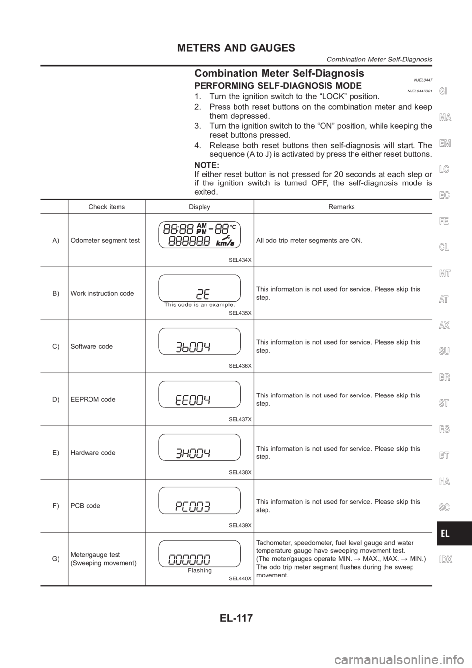
Check items Display Remarks
A) Odometer segment test
SEL434X
All odo trip meter segments are ON.
B) Work instruction code
SEL435X
This information is not used for service. Please skip this
step.
C) Software code
SEL436X
This information is not used for service. Please skip this
step.
D) EEPROM code
SEL437X
This information is not used for service. Please skip this
step.
E) Hardware code
SEL438X
This information is not used for service. Please skip this
step.
F) PCB code
SEL439X
This information is not used for service. Please skip this
step.
G)Meter/gauge test
(Sweeping movement)
SEL440X
Tachometer, speedometer, fuel level gauge and water
temperature gauge have sweeping movement test.
(The meter/gauges operate MIN.,MAX., MAX.,MIN.)
The odo trip meter segment flushes during the sweep
movement.
GI
MA
EM
LC
EC
FE
CL
MT
AT
AX
SU
BR
ST
RS
BT
HA
SC
IDX
METERS AND GAUGES
Combination Meter Self-Diagnosis
EL-117
Page 2529 of 3189
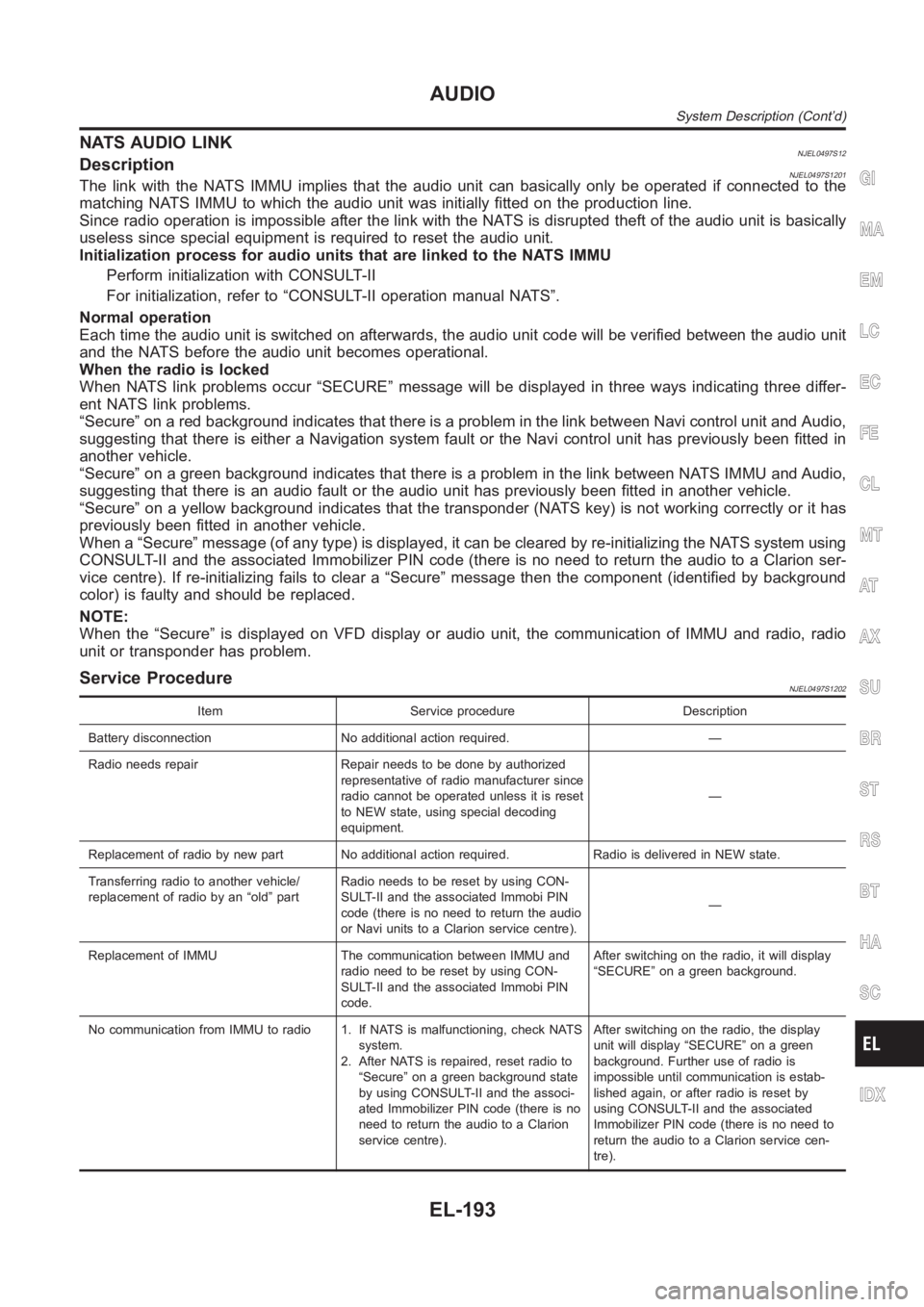
NATS AUDIO LINKNJEL0497S12DescriptionNJEL0497S1201The link with the NATS IMMU implies that the audio unit can basically only beoperated if connected to the
matching NATS IMMU to which the audio unit was initially fitted on the production line.
Since radio operation is impossible after the link with the NATS is disrupted theft of the audio unit is basically
useless since special equipment is required to reset the audio unit.
Initialization process for audio units that are linked to the NATS IMMU
Perform initialization with CONSULT-II
For initialization, refer to “CONSULT-II operation manual NATS”.
Normal operation
Each time the audio unit is switched on afterwards, the audio unit code willbe verified between the audio unit
and the NATS before the audio unit becomes operational.
When the radio is locked
When NATS link problems occur “SECURE” message will be displayed in three ways indicating three differ-
ent NATS link problems.
“Secure” on a red background indicates that there is a problem in the link between Navi control unit and Audio,
suggesting that there is either a Navigation system fault or the Navi control unit has previously been fitted in
another vehicle.
“Secure” on a green background indicates that there is a problem in the linkbetween NATS IMMU and Audio,
suggesting that there is an audio fault or the audio unit has previously been fitted in another vehicle.
“Secure” on a yellow background indicates that the transponder (NATS key)is not working correctly or it has
previously been fitted in another vehicle.
When a “Secure” message (of any type) is displayed, it can be cleared by re-initializing the NATS system using
CONSULT-II and the associated Immobilizer PIN code (there is no need to return the audio to a Clarion ser-
vice centre). If re-initializing fails to clear a “Secure” message then the component (identified by background
color) is faulty and should be replaced.
NOTE:
When the “Secure” is displayed on VFD display or audio unit, the communication of IMMU and radio, radio
unit or transponder has problem.
Service ProcedureNJEL0497S1202
Item Service procedure Description
Battery disconnection No additional action required. —
Radio needs repair Repair needs to be done by authorized
representative of radio manufacturer since
radio cannot be operated unless it is reset
to NEW state, using special decoding
equipment.—
Replacement of radio by new part No additional action required. Radio is delivered in NEW state.
Transferring radio to another vehicle/
replacement of radio by an “old” partRadio needs to be reset by using CON-
SULT-II and the associated Immobi PIN
code (there is no need to return the audio
or Navi units to a Clarion service centre).—
Replacement of IMMU The communication between IMMU and
radio need to be reset by using CON-
SULT-II and the associated Immobi PIN
code.After switching on the radio, it will display
“SECURE” on a green background.
No communication from IMMU to radio 1. If NATS is malfunctioning, check NATS
system.
2. After NATS is repaired, reset radio to
“Secure” on a green background state
by using CONSULT-II and the associ-
ated Immobilizer PIN code (there is no
need to return the audio to a Clarion
service centre).After switching on the radio, the display
unit will display “SECURE” on a green
background. Further use of radio is
impossible until communication is estab-
lished again, or after radio is reset by
using CONSULT-II and the associated
Immobilizer PIN code (there is no need to
return the audio to a Clarion service cen-
tre).
GI
MA
EM
LC
EC
FE
CL
MT
AT
AX
SU
BR
ST
RS
BT
HA
SC
IDX
AUDIO
System Description (Cont’d)
EL-193
Page 2802 of 3189
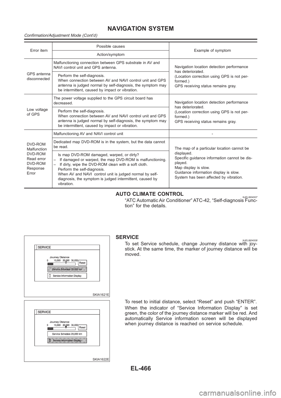
Error itemPossible causes
Example of symptom
Action/symptom
GPS antenna
disconnectedMalfunctioning connection between GPS substrate in AV and
NAVI control unit and GPS antenna.Navigation location detection performance
has deteriorated.
(Location correction using GPS is not per-
formed.)
GPS receiving status remains gray. Perform the self-diagnosis.
When connection between AV and NAVI control unit and GPS
antenna is judged normal by self-diagnosis, the symptom may
be intermittent, caused by impact or vibration.
Low voltage
of GPSThe power voltage supplied to the GPS circuit board has
decreased.Navigation location detection performance
has deteriorated.
(Location correction using GPS is not per-
formed.)
GPS receiving status remains gray. Perform the self-diagnosis.
When connection between AV and NAVI control unit and GPS
antenna is judged normal by self-diagnosis, the symptom may
be intermittent, caused by impact or vibration.
DVD-ROM
Malfunction
DVD-ROM
Read error
DVD-ROM
Response
ErrorMalfunctioning AV and NAVI control unit -
Dedicated map DVD-ROM is in the system, but the data cannot
be read.
The map of a particular location cannot be
displayed.
Specific guidance information cannot be dis-
played.
Map display is slow.
Guidance information display is slow.
System has been affected by vibration. Is map DVD-ROM damaged, warped, or dirty?
– If damaged or warped, the map DVD-ROM is malfunctioning.
– If dirty, wipe the DVD-ROM clean with a soft cloth.
Perform the self-diagnosis.
When AV and NAVI control unit is judged normal by self-
diagnosis, the symptom is judged intermittent, caused by
vibration.
AUTO CLIMATE CONTROLNJEL0604S07“ATC Automatic Air Conditioner” ATC-42, “Self-diagnosis Func-
tion” for the details.
SKIA1621E
SERVICENJEL0604S08To set Service schedule, change Journey distance with joy-
stick. At the same time, the marker of journey distance will be
moved.
SKIA1622E
To reset to initial distance, select “Reset” and push “ENTER”.
When the indicator of “Service Information Display” is set
green, the color of the journey distance marker will be red. And
automatically Service information screen will be displayed
when journey distance is reached on service schedule.
NAVIGATION SYSTEM
Confirmation/Adjustment Mode (Cont’d)
EL-466
Page 2943 of 3189
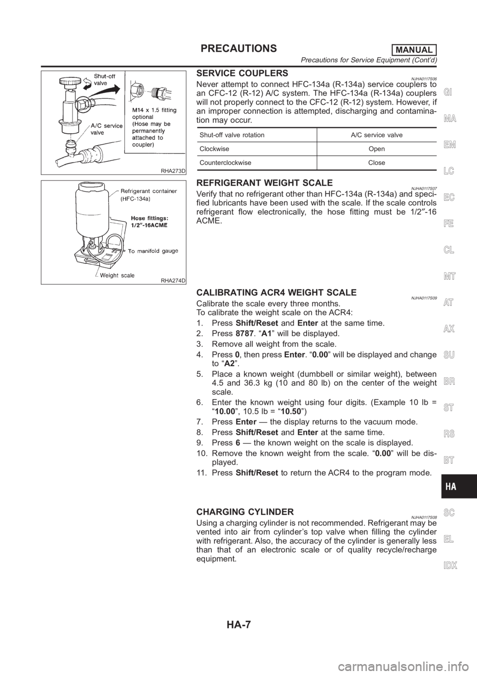
RHA273D
SERVICE COUPLERSNJHA0117S06Never attempt to connect HFC-134a (R-134a) service couplers to
an CFC-12 (R-12) A/C system. The HFC-134a (R-134a) couplers
will not properly connect to the CFC-12 (R-12) system. However, if
an improper connection is attempted, discharging and contamina-
tion may occur.
Shut-off valve rotation A/C service valve
Clockwise Open
Counterclockwise Close
RHA274D
REFRIGERANT WEIGHT SCALENJHA0117S07Verify that no refrigerant other than HFC-134a (R-134a) and speci-
fied lubricants have been used with the scale. If the scale controls
refrigerant flow electronically, the hose fitting must be 1/2″-16
ACME.
CALIBRATING ACR4 WEIGHT SCALENJHA0117S09Calibrate the scale every three months.
To calibrate the weight scale on the ACR4:
1. PressShift/ResetandEnterat the same time.
2. Press8787.“A1” will be displayed.
3. Remove all weight from the scale.
4. Press0, then pressEnter.“0.00” will be displayed and change
to “A2”.
5. Place a known weight (dumbbell or similar weight), between
4.5 and 36.3 kg (10 and 80 lb) on the center of the weight
scale.
6. Enter the known weight using four digits. (Example 10 lb =
“10.00”, 10.5 lb = “10.50”)
7. PressEnter— the display returns to the vacuum mode.
8. PressShift/ResetandEnterat the same time.
9. Press6— the known weight on the scale is displayed.
10. Remove the known weight from the scale. “0.00” will be dis-
played.
11. PressShift/Resetto return the ACR4 to the program mode.
CHARGING CYLINDERNJHA0117S08Using a charging cylinder is not recommended. Refrigerant may be
vented into air from cylinder’s top valve when filling the cylinder
with refrigerant. Also, the accuracy of the cylinder is generally less
than that of an electronic scale or of quality recycle/recharge
equipment.
GI
MA
EM
LC
EC
FE
CL
MT
AT
AX
SU
BR
ST
RS
BT
SC
EL
IDX
PRECAUTIONSMANUAL
Precautions for Service Equipment (Cont’d)
HA-7
Page 3073 of 3189
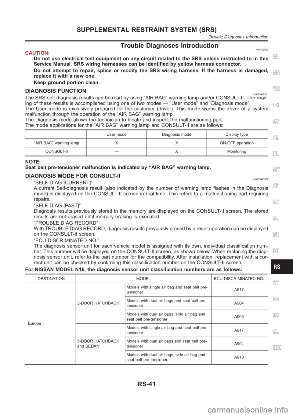
Trouble Diagnoses Introduction=NJRS0043CAUTION:
Do not use electrical test equipment on any circuit related to the SRS unless instructed to in this
Service Manual. SRS wiring harnesses can be identified by yellow harness connector.
Do not attempt to repair, splice or modify the SRS wiring harness. If the harness is damaged,
replace it with a new one.
Keep ground portion clean.
DIAGNOSIS FUNCTIONNJRS0043S01The SRS self-diagnosis results can be read by using “AIR BAG” warning lamp and/or CONSULT-II. The read-
ing of these results is accomplished using one of two modes — “User mode” and“Diagnosis mode”.
The User mode is exclusively prepared for the customer (driver). This modewarns the driver of a system
malfunction through the operation of the “AIR BAG” warning lamp.
The Diagnosis mode allows the technician to locate and inspect the malfunctioning part.
The mode applications for the “AIR BAG” warning lamp and CONSULT-II are as follows:
User mode Diagnosis mode Display type
“AIR BAG” warning lamp X X ON-OFF operation
CONSULT-II — X Monitoring
NOTE:
Seat belt pre-tensioner malfunction is indicated by “AIR BAG” warning lamp.
DIAGNOSIS MODE FOR CONSULT-IINJRS0043S02“SELF-DIAG [CURRENT]”
A current Self-diagnosis result (also indicated by the number of warning lamp flashes in the Diagnosis
mode) is displayed on the CONSULT-II screen in real time. This refers to a malfunctioning part requiring
repairs.
“SELF-DIAG [PAST]”
Diagnosis results previously stored in the memory are displayed on the CONSULT-II screen. The stored
results are not erased until memory erasing is executed.
“TROUBLE DIAG RECORD”
With TROUBLE DIAG RECORD, diagnosis results previously erased by a reset operation can be displayed
on the CONSULT-II screen.
“ECU DISCRIMINATED NO.”
The diagnosis sensor unit for each vehicle model is assigned with its own, individual classification num-
ber. This number will be displayed on the CONSULT-II screen, as shown below. When replacing the diag-
nosis sensor unit, refer to the part number for the compatibility. After installation, replacement with a cor-
rect unit can be checked by confirming this classification number on the CONSULT-II screen.
For NISSAN MODEL N16, the diagnosis sensor unit classification numbers are as follows:
DESTINATION MODEL ECU DISCRIMINATED NO.
Europe3-DOOR HATCHBACKModels with single air bag and seat belt pre-
tensionerA917
Models with dual air bags and seat belt pre-
tensionerA904
Models with dual air bags, side air bag and
seat belt pre-tensionerA905
5-DOOR HATCHBACK
and SEDANModels with single air bag and seat belt pre-
tensionerA917
Models with dual air bags and seat belt pre-
tensionerA904
Models with dual air bags, side air bag and
seat belt pre-tensionerA918
GI
MA
EM
LC
EC
FE
CL
MT
AT
AX
SU
BR
ST
BT
HA
SC
EL
IDX
SUPPLEMENTAL RESTRAINT SYSTEM (SRS)
Trouble Diagnoses Introduction
RS-41