service schedule NISSAN ALMERA N16 2003 Electronic Repair Manual
[x] Cancel search | Manufacturer: NISSAN, Model Year: 2003, Model line: ALMERA N16, Model: NISSAN ALMERA N16 2003Pages: 3189, PDF Size: 54.76 MB
Page 60 of 3189
NJMA0005
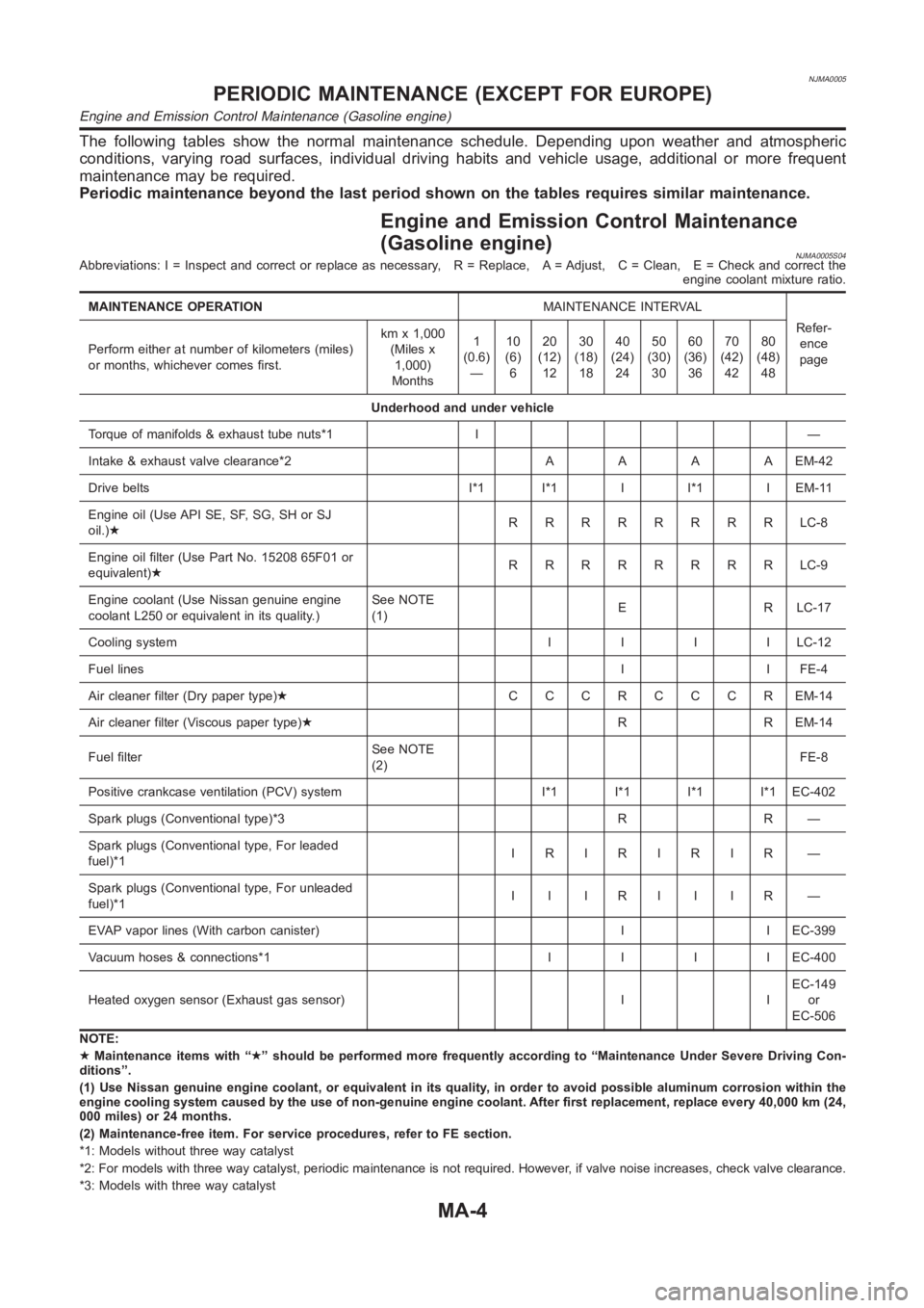
The following tables show the normal maintenance schedule. Depending upon weather and atmospheric
conditions, varying road surfaces, individual driving habits and vehicle usage, additional or more frequent
maintenance may be required.
Periodic maintenance beyond the last period shown on the tables requires similar maintenance.
Engine and Emission Control Maintenance
(Gasoline engine)
NJMA0005S04Abbreviations: I = Inspect and correct or replace as necessary, R = Replace, A = Adjust, C = Clean, E = Check and correct the
engine coolant mixture ratio.
MAINTENANCE OPERATIONMAINTENANCE INTERVAL
Refer-
ence
page Perform either at number of kilometers (miles)
or months, whichever comes first.kmx1,000
(Miles x
1,000)
Months1
(0.6)
—10
(6)
620
(12)
1230
(18)
1840
(24)
2450
(30)
3060
(36)
3670
(42)
4280
(48)
48
Underhood and under vehicle
Torque of manifolds & exhaust tube nuts*1 I —
Intake & exhaust valve clearance*2AAAAEM-42
Drive belts I*1 I*1 I I*1 I EM-11
Engine oil (Use API SE, SF, SG, SH or SJ
oil.)★RRRRRRRRLC-8
Engine oil filter (Use Part No. 15208 65F01 or
equivalent)★RRRRRRRRLC-9
Engine coolant (Use Nissan genuine engine
coolant L250 or equivalent in its quality.)See NOTE
(1)E R LC-17
Cooling systemIIIILC-12
Fuel linesI I FE-4
Air cleaner filter (Dry paper type)★CCCRCCCREM-14
Air cleaner filter (Viscous paper type)★R R EM-14
Fuel filterSee NOTE
(2)FE-8
Positive crankcase ventilation (PCV) system I*1 I*1 I*1 I*1 EC-402
Spark plugs (Conventional type)*3 R R —
Spark plugs (Conventional type, For leaded
fuel)*1IRIRIRIR —
Spark plugs (Conventional type, For unleaded
fuel)*1IIIRIIIR —
EVAP vapor lines (With carbon canister) I I EC-399
Vacuum hoses & connections*1IIIIEC-400
Heated oxygen sensor (Exhaust gas sensor) I IEC-149
or
EC-506
NOTE:
★Maintenance items with “★” should be performed more frequently according to “Maintenance Under Severe Driving Con-
ditions”.
(1) Use Nissan genuine engine coolant, or equivalent in its quality, in order to avoid possible aluminum corrosion within the
engine cooling system caused by the use of non-genuine engine coolant. After first replacement, replace every 40,000 km (24,
000 miles) or 24 months.
(2) Maintenance-free item. For service procedures, refer to FE section.
*1: Models without three way catalyst
*2: For models with three way catalyst, periodic maintenance is not requir
ed. However, if valve noise increases, check valve clearance.
*3: Models with three way catalyst
PERIODIC MAINTENANCE (EXCEPT FOR EUROPE)
Engine and Emission Control Maintenance (Gasoline engine)
MA-4
Page 63 of 3189
NJMA0043
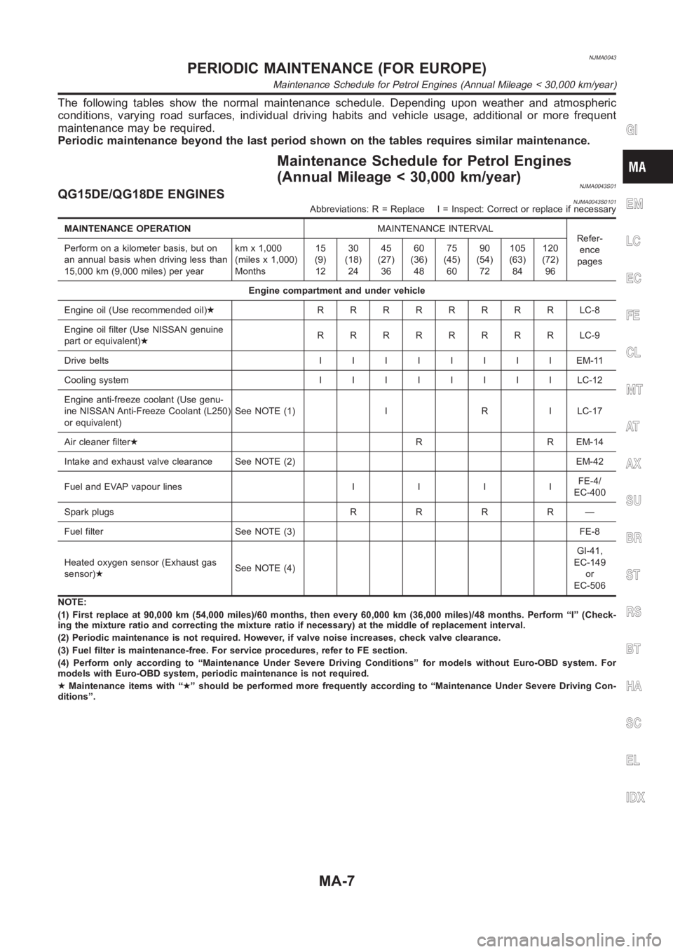
The following tables show the normal maintenance schedule. Depending upon weather and atmospheric
conditions, varying road surfaces, individual driving habits and vehicle usage, additional or more frequent
maintenance may be required.
Periodic maintenance beyond the last period shown on the tables requires similar maintenance.
Maintenance Schedule for Petrol Engines
(Annual Mileage < 30,000 km/year)
NJMA0043S01QG15DE/QG18DE ENGINESNJMA0043S0101Abbreviations: R = Replace I = Inspect: Correct or replace if necessary
MAINTENANCE OPERATIONMAINTENANCE INTERVAL
Refer-
ence
pages Perform on a kilometer basis, but on
an annual basis when driving less than
15,000 km (9,000 miles) per yearkmx1,000
(miles x 1,000)
Months15
(9)
1230
(18)
2445
(27)
3660
(36)
4875
(45)
6090
(54)
72105
(63)
84120
(72)
96
Engine compartment and under vehicle
Engine oil (Use recommended oil)★RRRRRRRRLC-8
Engine oil filter (Use NISSAN genuine
part or equivalent)★RRRRRRRRLC-9
Drive beltsIIIIIIIIEM-11
Cooling systemIIIIIIIILC-12
Engine anti-freeze coolant (Use genu-
ine NISSAN Anti-Freeze Coolant (L250)
or equivalent)See NOTE (1) I R I LC-17
Air cleaner filter★R R EM-14
Intake and exhaust valve clearance See NOTE (2) EM-42
Fuel and EVAP vapour linesIIIIFE-4/
EC-400
Spark plugsRRRR—
Fuel filter See NOTE (3) FE-8
Heated oxygen sensor (Exhaust gas
sensor)★See NOTE (4)GI-41,
EC-149
or
EC-506
NOTE:
(1) First replace at 90,000 km (54,000 miles)/60 months, then every 60,000km (36,000 miles)/48 months. Perform “I” (Check-
ing the mixture ratio and correcting the mixture ratio if necessary) at themiddle of replacement interval.
(2) Periodic maintenance is not required. However, if valve noise increases, check valve clearance.
(3) Fuel filter is maintenance-free. For service procedures, refer to FE section.
(4) Perform only according to “Maintenance Under Severe Driving Conditions” for models without Euro-OBD system. For
models with Euro-OBD system, periodic maintenance is not required.
★Maintenance items with “★” should be performed more frequently according to “Maintenance Under Severe Driving Con-
ditions”.
GI
EM
LC
EC
FE
CL
MT
AT
AX
SU
BR
ST
RS
BT
HA
SC
EL
IDX
PERIODIC MAINTENANCE (FOR EUROPE)
Maintenance Schedule for Petrol Engines (Annual Mileage < 30,000 km/year)
MA-7
Page 69 of 3189
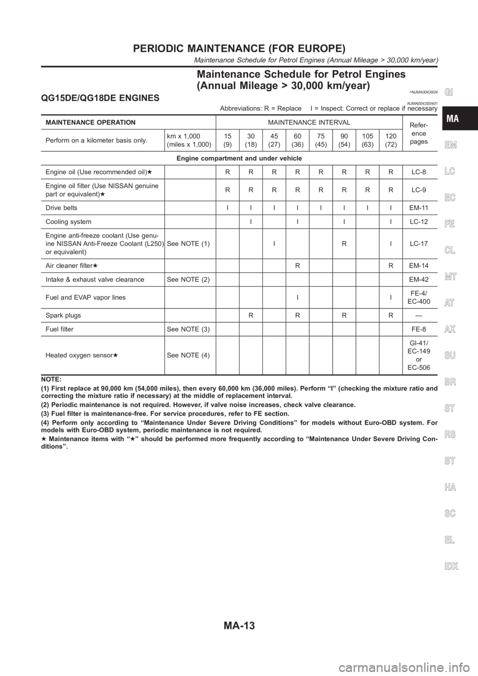
Maintenance Schedule for Petrol Engines
(Annual Mileage > 30,000 km/year)
=NJMA0043S04QG15DE/QG18DE ENGINESNJMA0043S0401Abbreviations: R = Replace I = Inspect: Correct or replace if necessary
MAINTENANCE OPERATIONMAINTENANCE INTERVAL
Refer-
ence
pages Perform on a kilometer basis only.kmx1,000
(miles x 1,000)15
(9)30
(18)45
(27)60
(36)75
(45)90
(54)105
(63)120
(72)
Engine compartment and under vehicle
Engine oil (Use recommended oil)★RRRRRRRRLC-8
Engine oil filter (Use NISSAN genuine
part or equivalent)★RRRRRRRRLC-9
Drive beltsIIIIIIIIEM-11
Cooling systemIIIILC-12
Engine anti-freeze coolant (Use genu-
ine NISSAN Anti-Freeze Coolant (L250)
or equivalent)See NOTE (1) I R I LC-17
Air cleaner filter★R R EM-14
Intake & exhaust valve clearance See NOTE (2) EM-42
Fuel and EVAP vapor lines I IFE-4/
EC-400
Spark plugsRRRR—
Fuel filter See NOTE (3) FE-8
Heated oxygen sensor★See NOTE (4)GI-41/
EC-149
or
EC-506
NOTE:
(1) First replace at 90,000 km (54,000 miles), then every 60,000 km (36,000miles). Perform “I” (checking the mixture ratio and
correcting the mixture ratio if necessary) at the middle of replacement interval.
(2) Periodic maintenance is not required. However, if valve noise increases, check valve clearance.
(3) Fuel filter is maintenance-free. For service procedures, refer to FE section.
(4) Perform only according to “Maintenance Under Severe Driving Conditions” for models without Euro-OBD system. For
models with Euro-OBD system, periodic maintenance is not required.
★Maintenance items with “★” should be performed more frequently according to “Maintenance Under Severe Driving Con-
ditions”.
GI
EM
LC
EC
FE
CL
MT
AT
AX
SU
BR
ST
RS
BT
HA
SC
EL
IDX
PERIODIC MAINTENANCE (FOR EUROPE)
Maintenance Schedule for Petrol Engines (Annual Mileage > 30,000 km/year)
MA-13
Page 370 of 3189
![NISSAN ALMERA N16 2003 Electronic Repair Manual EC-40
[QG (WITH EURO-OBD)]
ON BOARD DIAGNOSTIC (OBD) SYSTEM
If a 1st trip DTC is stored in the ECM, the time data will be “[1t]”.
FREEZE FRAME DATA AND 1ST TRIP FREEZE FRAME DATA
The ECM records t NISSAN ALMERA N16 2003 Electronic Repair Manual EC-40
[QG (WITH EURO-OBD)]
ON BOARD DIAGNOSTIC (OBD) SYSTEM
If a 1st trip DTC is stored in the ECM, the time data will be “[1t]”.
FREEZE FRAME DATA AND 1ST TRIP FREEZE FRAME DATA
The ECM records t](/img/5/57350/w960_57350-369.png)
EC-40
[QG (WITH EURO-OBD)]
ON BOARD DIAGNOSTIC (OBD) SYSTEM
If a 1st trip DTC is stored in the ECM, the time data will be “[1t]”.
FREEZE FRAME DATA AND 1ST TRIP FREEZE FRAME DATA
The ECM records the driving conditions such as fuel system status, calculated load value, engine coolant tem-
perature, short term fuel trim, long term fuel trim, engine speed, vehicle speed, base fuel schedule and intake
air temperature at the moment a malfunction is detected.
Data which are stored in the ECM memory, along with the 1st trip DTC, are called 1st trip freeze frame data.
The data, stored together with the DTC data, are called freeze frame data and displayed on CONSULT-II or
GST. The 1st trip freeze frame data can only be displayed on the CONSULT-II screen, not on the GST. For
details, see EC-90, "
Freeze Frame Data and 1st Trip Freeze Frame Data" .
Only one set of freeze frame data (either 1st trip freeze frame data or freeze frame data) can be stored in the
ECM. 1st trip freeze frame data is stored in the ECM memory along with the 1st trip DTC. There is no priority
for 1st trip freeze frame data and it is updated each time a different 1st trip DTC is detected. However, once
freeze frame data (2nd trip detection/MI on) is stored in the ECM memory, 1st trip freeze frame data is no
longer stored. Remember, only one set of freeze frame data can be stored in the ECM. The ECM has the fol-
lowing priorities to update the data.
For example, the EGR malfunction (Priority: 2) was detected and the freeze frame data was stored in the 2nd
trip. After that when the misfire (Priority: 1) is detected in another trip, the freeze frame data will be updated
from the EGR malfunction to the misfire. The 1st trip freeze frame data is updated each time a different mal-
function is detected. There is no priority for 1st trip freeze frame data. However, once freeze frame data is
stored in the ECM memory, 1st trip freeze data is no longer stored (because only one freeze frame data or 1st
trip freeze frame data can be stored in the ECM). If freeze frame data is stored in the ECM memory and freeze
frame data with the same priority occurs later, the first (original) freeze frame data remains unchanged in the
ECM memory.
Both 1st trip freeze frame data and freeze frame data (along with the DTCs) are cleared when the ECM mem-
ory is erased. Procedures for clearing the ECM memory are described in EC-48, "
HOW TO ERASE EMIS-
SION-RELATED DIAGNOSTIC INFORMATION" .
SYSTEM READINESS TEST (SRT) CODE
System Readiness Test (SRT) code is specified in Mode 1 of ISO 15031-5.
As part of an enhanced emissions test for Inspection & Maintenance (I/M), certain states require the status of
SRT be used to indicate whether the ECM has completed self-diagnosis of major emission systems and com-
ponents. Completion must be verified in order for the emissions inspection to proceed.
If a vehicle is rejected for a State emissions inspection due to one or more SRT items indicating “INCMP”, use
the information in this Service Manual to set the SRT to “CMPLT”.
In most cases the ECM will automatically complete its self-diagnosis cycle during normal usage, and the SRT
status will indicate “CMPLT” for each application system. Once set as “CMPLT”, the SRT status remains
“CMPLT” until the self-diagnosis memory is erased.
Occasionally, certain portions of the self-diagnostic test may not be completed as a result of the customer's
normal driving pattern; the SRT will indicate “INCMP” for these items.
NOTE:
The SRT will also indicate “INCMP” if the self-diagnosis memory is erased for any reason or if the ECM mem-
ory power supply is interrupted for several hours.
PBIB0911E
Priority Items
1Freeze frame data Misfire — DTC: P0300 - P0304
Fuel Injection System Function — DTC: P0171, P0172
2 Except the above items (Includes A/T related items)
3 1st trip freeze frame data
Page 395 of 3189
![NISSAN ALMERA N16 2003 Electronic Repair Manual TROUBLE DIAGNOSIS
EC-65
[QG (WITH EURO-OBD)]
C
D
E
F
G
H
I
J
K
L
MA
EC
Basic InspectionEBS00K3O
1.INSPECTION START
1. Check service records for any recent repairs that may indicate a related malfuncti NISSAN ALMERA N16 2003 Electronic Repair Manual TROUBLE DIAGNOSIS
EC-65
[QG (WITH EURO-OBD)]
C
D
E
F
G
H
I
J
K
L
MA
EC
Basic InspectionEBS00K3O
1.INSPECTION START
1. Check service records for any recent repairs that may indicate a related malfuncti](/img/5/57350/w960_57350-394.png)
TROUBLE DIAGNOSIS
EC-65
[QG (WITH EURO-OBD)]
C
D
E
F
G
H
I
J
K
L
MA
EC
Basic InspectionEBS00K3O
1.INSPECTION START
1. Check service records for any recent repairs that may indicate a related malfunction, or a current need for
scheduled maintenance.
2. Open engine hood and check the following:
–Harness connectors for improper connections
–Wiring harness for improper connections, pinches and cut
–Vacuum hoses for splits, kinks and improper connections
–Hoses and ducts for leaks
–Air cleaner clogging
–Gasket
3. Confirm that electrical or mechanical loads are not applied.
–Headlamp switch is OFF.
–Air conditioner switch is OFF.
–Rear window defogger switch is OFF.
–Steering wheel is in the straight-ahead position, etc.
4. Start engine and warm it up until engine coolant temperature
indicator points the middle of gauge.
Ensure engine stays below 1,000 rpm.
5. Run engine at about 2,000 rpm for about 2 minutes under no-
load.
6. Make sure that no DTC is displayed with CONSULT-II or GST.
OK or NG
OK >> GO TO 3.
NG >> GO TO 2.
2.REPAIR OR REPLACE
Repair or replace components as necessary according to corresponding “Diagnostic Procedure”.
>> GO TO 3.
SEF983U
SEF976U
SEF977U
Page 420 of 3189
![NISSAN ALMERA N16 2003 Electronic Repair Manual EC-90
[QG (WITH EURO-OBD)]
TROUBLE DIAGNOSIS
WORK SUPPORT MODE
Work Item
*: This function is not necessary in the usual service procedure.
SELF-DIAG RESULTS MODE
Self Diagnostic Item
Regarding items o NISSAN ALMERA N16 2003 Electronic Repair Manual EC-90
[QG (WITH EURO-OBD)]
TROUBLE DIAGNOSIS
WORK SUPPORT MODE
Work Item
*: This function is not necessary in the usual service procedure.
SELF-DIAG RESULTS MODE
Self Diagnostic Item
Regarding items o](/img/5/57350/w960_57350-419.png)
EC-90
[QG (WITH EURO-OBD)]
TROUBLE DIAGNOSIS
WORK SUPPORT MODE
Work Item
*: This function is not necessary in the usual service procedure.
SELF-DIAG RESULTS MODE
Self Diagnostic Item
Regarding items of “DTC and 1st trip DTC”, refer to EC-10, "INDEX FOR DTC" .
Freeze Frame Data and 1st Trip Freeze Frame Data
*1: The items are the same as those of 1st trip freeze frame data. WORK ITEM CONDITION USAGE
FUEL PRESSURE RELEASE
●FUEL PUMP WILL STOP BY TOUCHING “START” DUR-
ING IDLING.
CRANK A FEW TIMES AFTER ENGINE STALLS.When releasing fuel pressure
from fuel line
IDLE AIR VOL LEARN
●THE IDLE AIR VOLUME THAT KEEPS THE ENGINE
WITHIN THE SPECIFIED RANGE IS MEMORIZED IN
ECM.When learning the idle air volume
SELF-LEARNING CONT
●THE COEFFICIENT OF SELF-LEARNING CONTROL
MIXTURE RATIO RETURNS TO THE ORIGINAL COEF-
FICIENT.When clearing the coefficient of
self-learning control value
TARGET IDLE RPM ADJ
*●IDLE CONDITION When setting target idle speed
TARGET IGN TIM ADJ
*●IDLE CONDITION When adjusting target ignition tim-
ing
After adjustment, confirm target
ignition timing with a timing light.
Freeze frame data
item*1Description
DIAG TROUBLE
CODE
[PXXXX]
●The engine control component part/control system has a trouble code, it is displayed as “PXXXX”. (Refer
to EC-10, "
INDEX FOR DTC" .)
FUEL SYS-B1
●“Fuel injection system status” at the moment a malfunction is detected is displayed.
●One mode in the following is displayed.
“MODE 2”: Open loop due to detected system malfunction
“MODE 3”: Open loop due to driving conditions (power enrichment, deceleration enrichment)
“MODE 4”: Closed loop - using oxygen sensor(s) as feedback for fuel control
“MODE 5”: Open loop - has not yet satisfied condition to go to closed loop
CAL/LD VALUE [%]
●The calculated load value at the moment a malfunction is detected is displayed.
COOLANT TEMP [°C]
or [°F]
●The engine coolant temperature at the moment a malfunction is detected is displayed.
L-FUEL TRIM-B1 [%]
●“Long-term fuel trim” at the moment a malfunction is detected is displayed.
●The long-term fuel trim indicates much more gradual feedback compensation to the base fuel schedule
than short-term fuel trim.
S-FUEL TRIM-B1 [%]
●“Short-term fuel trim” at the moment a malfunction is detected is displayed.
●The short-term fuel trim indicates dynamic or instantaneous feedback compensation to the base fuel
schedule.
ENGINE SPEED
[rpm]
●The engine speed at the moment a malfunction is detected is displayed.
VHCL SPEED [km/h]
or [mph]
●The vehicle speed at the moment a malfunction is detected is displayed.
B/FUEL SCHDL
[msec]
●The base fuel schedule at the moment a malfunction is detected is displayed.
INT/A TEMP SE [°C]
or [°F]
●The intake air temperature at the moment a malfunction is detected is displayed.
Page 773 of 3189
![NISSAN ALMERA N16 2003 Electronic Repair Manual TROUBLE DIAGNOSIS
EC-443
[QG (WITHOUT EURO-OBD)]
C
D
E
F
G
H
I
J
K
L
MA
EC
Basic InspectionEBS00KEU
1.INSPECTION START
1. Check service records for any recent repairs that may indicate a related malfu NISSAN ALMERA N16 2003 Electronic Repair Manual TROUBLE DIAGNOSIS
EC-443
[QG (WITHOUT EURO-OBD)]
C
D
E
F
G
H
I
J
K
L
MA
EC
Basic InspectionEBS00KEU
1.INSPECTION START
1. Check service records for any recent repairs that may indicate a related malfu](/img/5/57350/w960_57350-772.png)
TROUBLE DIAGNOSIS
EC-443
[QG (WITHOUT EURO-OBD)]
C
D
E
F
G
H
I
J
K
L
MA
EC
Basic InspectionEBS00KEU
1.INSPECTION START
1. Check service records for any recent repairs that may indicate a related malfunction, or a current need for
scheduled maintenance.
2. Open engine hood and check the following:
–Harness connectors for improper connections
–Wiring harness for improper connections, pinches and cut
–Vacuum hoses for splits, kinks and improper connections
–Hoses and ducts for leaks
–Air cleaner clogging
–Gasket
3. Confirm that electrical or mechanical loads are not applied.
–Headlamp switch is OFF.
–Air conditioner switch is OFF.
–Rear window defogger switch is OFF.
–Steering wheel is in the straight-ahead position, etc.
4. Start engine and warm it up until engine coolant temperature
indicator points the middle of gauge.
Ensure engine stays below 1,000 rpm.
5. Run engine at about 2,000 rpm for about 2 minutes under no-
load.
6. Make sure that no DTC is displayed with CONSULT-II or ECM.
OK or NG
OK >> GO TO 3.
NG >> GO TO 2.
2.REPAIR OR REPLACE
Repair or replace components as necessary according to corresponding “Diagnostic Procedure”.
>> GO TO 3.
SEF983U
SEF976U
SEF977U
Page 798 of 3189
![NISSAN ALMERA N16 2003 Electronic Repair Manual EC-468
[QG (WITHOUT EURO-OBD)]
TROUBLE DIAGNOSIS
*: This function is not necessary in the usual service procedure.
SELF-DIAG RESULTS MODE
Self Diagnostic Item
Regarding items of “DTC and 1st trip DT NISSAN ALMERA N16 2003 Electronic Repair Manual EC-468
[QG (WITHOUT EURO-OBD)]
TROUBLE DIAGNOSIS
*: This function is not necessary in the usual service procedure.
SELF-DIAG RESULTS MODE
Self Diagnostic Item
Regarding items of “DTC and 1st trip DT](/img/5/57350/w960_57350-797.png)
EC-468
[QG (WITHOUT EURO-OBD)]
TROUBLE DIAGNOSIS
*: This function is not necessary in the usual service procedure.
SELF-DIAG RESULTS MODE
Self Diagnostic Item
Regarding items of “DTC and 1st trip DTC”, refer to EC-406, "INDEX FOR DTC" .)
Freeze Frame Data and 1st Trip Freeze Frame Data
*1: The items are the same as those of 1st trip freeze frame data. SELF-LEARNING CONT
●THE COEFFICIENT OF SELF-LEARNING CONTROL
MIXTURE RATIO RETURNS TO THE ORIGINAL COEF-
FICIENT.When clearing the coefficient of
self-learning control value
TARGET IDLE RPM ADJ
*●IDLE CONDITION When setting target idle speed
TARGET IGN TIM ADJ
*●IDLE CONDITION When adjusting target ignition tim-
ing
After adjustment, confirm target
ignition timing with a timing light. WORK ITEM CONDITION USAGE
Freeze frame data
item*1Description
DIAG TROUBLE
CODE
[PXXXX]
●The engine control component part/control system has a trouble code, it is displayed as “PXXXX”. (Refer
to EC-406, "
INDEX FOR DTC" .)
FUEL SYS-B1
●“Fuel injection system status” at the moment a malfunction is detected is displayed.
●One mode in the following is displayed.
“MODE 2”: Open loop due to detected system malfunction
“MODE 3”: Open loop due to driving conditions (power enrichment, deceleration enrichment)
“MODE 4”: Closed loop - using oxygen sensor(s) as feedback for fuel control
“MODE 5”: Open loop - has not yet satisfied condition to go to closed loop
CAL/LD VALUE [%]
●The calculated load value at the moment a malfunction is detected is displayed.
COOLANT TEMP [°C]
or [°F]
●The engine coolant temperature at the moment a malfunction is detected is displayed.
L-FUEL TRIM-B1 [%]
●“Long-term fuel trim” at the moment a malfunction is detected is displayed.
●The long-term fuel trim indicates much more gradual feedback compensation to the base fuel schedule
than short-term fuel trim.
S-FUEL TRIM-B1 [%]
●“Short-term fuel trim” at the moment a malfunction is detected is displayed.
●The short-term fuel trim indicates dynamic or instantaneous feedback compensation to the base fuel
schedule.
ENGINE SPEED
[rpm]
●The engine speed at the moment a malfunction is detected is displayed.
VHCL SPEED [km/h]
or [mph]
●The vehicle speed at the moment a malfunction is detected is displayed.
B/FUEL SCHDL
[msec]
●The base fuel schedule at the moment a malfunction is detected is displayed.
INT/A TEMP SE [°C]
or [°F]
●The intake air temperature at the moment a malfunction is detected is displayed.
Page 1102 of 3189
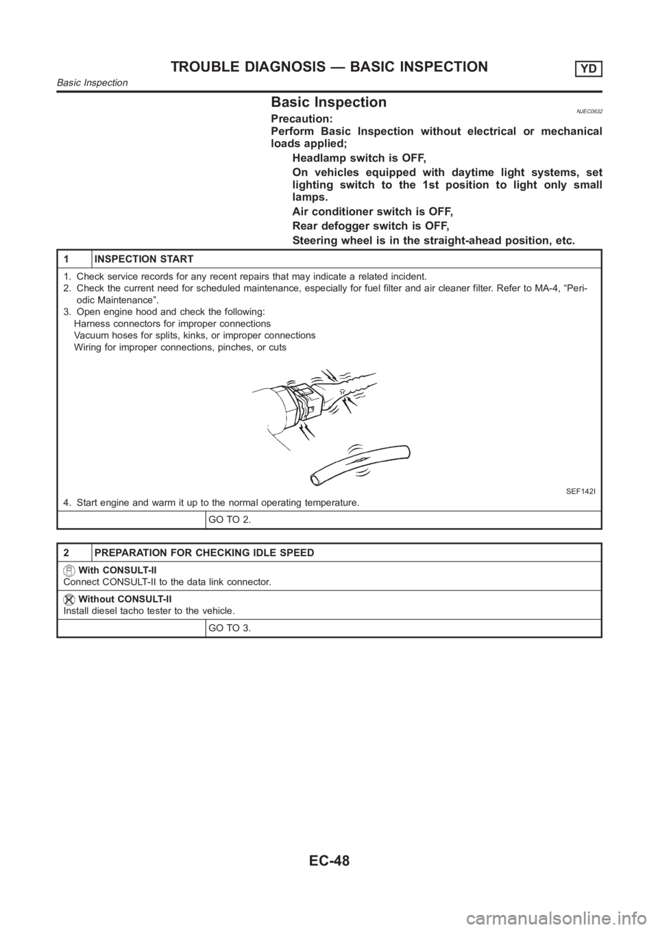
Basic InspectionNJEC0632Precaution:
Perform Basic Inspection without electrical or mechanical
loads applied;
Headlamp switch is OFF,
On vehicles equipped with daytime light systems, set
lighting switch to the 1st position to light only small
lamps.
Air conditioner switch is OFF,
Rear defogger switch is OFF,
Steering wheel is in the straight-ahead position, etc.
1 INSPECTION START
1. Check service records for any recent repairs that may indicate a relatedincident.
2. Check the current need for scheduled maintenance, especially for fuel filter and air cleaner filter. Refer to MA-4, “Peri-
odic Maintenance”.
3. Open engine hood and check the following:
Harness connectors for improper connections
Vacuum hoses for splits, kinks, or improper connections
Wiring for improper connections, pinches, or cuts
SEF142I
4. Start engine and warm it up to the normal operating temperature.
GO TO 2.
2 PREPARATION FOR CHECKING IDLE SPEED
With CONSULT-II
Connect CONSULT-II to the data link connector.
Without CONSULT-II
Install diesel tacho tester to the vehicle.
GO TO 3.
TROUBLE DIAGNOSIS — BASIC INSPECTIONYD
Basic Inspection
EC-48
Page 1460 of 3189
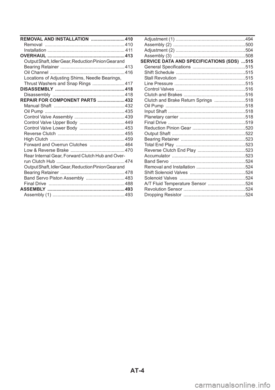
AT-4
REMOVAL AND INSTALLATION ...........................410
Removal ...............................................................410
Installation .............................................................411
OVERHAUL .............................................................413
Output Shaft, Idler Gear, Reduction Pinion Gear and
Bearing Retainer ...................................................413
Oil Channel ...........................................................416
Locations of Adjusting Shims, Needle Bearings,
Thrust Washers and Snap Rings ..........................417
DISASSEMBLY .......................................................418
Disassembly .........................................................418
REPAIR FOR COMPONENT PARTS ......................432
Manual Shaft ........................................................432
Oil Pump ...............................................................435
Control Valve Assembly ........................................439
Control Valve Upper Body ....................................449
Control Valve Lower Body ....................................453
Reverse Clutch .....................................................455
High Clutch ...........................................................459
Forward and Overrun Clutches ............................464
Low & Reverse Brake ...........................................470
Rear Internal Gear, Forward Clutch Hub and Over-
run Clutch Hub ......................................................474
Output Shaft, Idler Gear, Reduction Pinion Gear and
Bearing Retainer ...................................................478
Band Servo Piston Assembly ...............................483
Final Drive ............................................................488
ASSEMBLY .............................................................493
Assembly (1) .........................................................493Adjustment (1) .......................................................494
Assembly (2) .........................................................500
Adjustment (2) .......................................................504
Assembly (3) .........................................................508
SERVICE DATA AND SPECIFICATIONS (SDS) ....515
General Specifications ......................................... .515
Shift Schedule .......................................................515
Stall Revolution .....................................................515
Line Pressure ........................................................515
Control Valves .......................................................516
Clutch and Brakes .................................................516
Clutch and Brake Return Springs .........................518
Oil Pump ......................................................
.........518
Input Shaft .............................................................518
Planetary carrier ....................................................518
Final Drive .............................................................519
Reduction Pinion Gear ..........................................520
Output Shaft ..........................................................522
Bearing Retainer ...................................................523
Total End Play .......................................................523
Reverse Clutch End Play ......................................523
Accumulator ..........................................................523
Band Servo ...........................................................524
Removal and Installation .......................................524
Shift Solenoid Valves ............................................524
Solenoid Valves ....................................................524
A/T Fluid Temperature Sensor ..............................524
Revolution Sensor .................................................524
Dropping Resistor .................................................524