warning lights NISSAN ALMERA N16 2003 Electronic Repair Manual
[x] Cancel search | Manufacturer: NISSAN, Model Year: 2003, Model line: ALMERA N16, Model: NISSAN ALMERA N16 2003Pages: 3189, PDF Size: 54.76 MB
Page 2473 of 3189

from key switch terminal 2
to smart entrance control unit terminal 5.
Ground is supplied
from body grounds B9, B21 and D96 (Hatchback) or B308 (Sedan)
through front door switch (driver side) terminal 3 and 2
to smart entrance control unit terminal 43.
And, then smart entrance control unit receives any door lock signal.
LIGHT WARNING CHIMENJEL0453S02With ignition switch OFF, driver’s door open, and lighting switch in 1ST or2ND position, warning chime will
sound. Power is supplied.
from lighting switch terminal 12
through daytime light control unit terminals 11 and 10 (with daytime lightsystem)
to smart entrance control unit terminal 17
Ground is supplied
from front door switch (driver side) terminal 2
to smart entrance control unit terminal 43.
Front door switch (driver side) terminal 3 is grounded through body grounds B9, B21 and D96 (Hatchback) or
B308 (Sedan).
System Description/YD Engine Models without
Common Rail and K9K Engine Models
NJEL0550The warning chime is controlled by the time control unit.
The warning chime is located in the time control unit.
Power is supplied at all times
through 15A fuse [No. 5, located in fuse block (J/B)]
to time control unit terminal 9.
through 10A fuse [No. 12, located in the fuse block (J/B)]
to key switch terminal 1.
through 10A fuse (No. 38, located in the fuse and fusible link box)
to lighting switch terminal 11.
With the ignition switch in the ON or START position, power is supplied
through 10A fuse [No. 10, located in the fuse block (J/B)]
to time control unit terminal 1.
Ground is supplied to time control unit terminal 16 through body grounds M28 and M67.
When a signal, or combination of signals, is received by the time control unit, the warning chime will sound.
IGNITION KEY WARNING CHIMENJEL0550S01With the key in the ignition switch in the OFF position, the driver’s door open and driver’s door locked, the
warning chime will sound. Power is supplied
from key switch terminal 2
to time control unit terminal 22.
Ground is supplied
from body grounds B9, B21 and D96 (Hatchback) or B308 (Sedan)
through front door switch (driver side) terminal 3 and 2
to time control unit terminal 6, and
Ground is interrupted,
from body grounds M28 and M67
to time control unit terminal 35
LIGHT WARNING CHIMENJEL0550S02With ignition switch OFF, driver’s door open, and lighting switch in 1ST or2ND position, warning chime will
sound. Power is supplied.
from lighting switch terminal 12
to time control unit terminal 10
GI
MA
EM
LC
EC
FE
CL
MT
AT
AX
SU
BR
ST
RS
BT
HA
SC
IDX
WARNING CHIME
System Description/QG Engine Models and YD Engine Models with Common Rail(Cont’d)
EL-137
Page 3074 of 3189

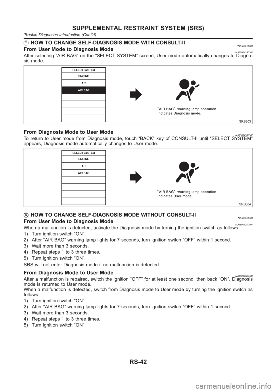
HOW TO CHANGE SELF-DIAGNOSIS MODE WITH CONSULT-II=NJRS0043S03From User Mode to Diagnosis ModeNJRS0043S0301After selecting “AIR BAG” on the “SELECT SYSTEM” screen, User mode automatically changes to Diagno-
sis mode.
SRS803
From Diagnosis Mode to User ModeNJRS0043S0302To return to User mode from Diagnosis mode, touch “BACK” key of CONSULT-II until “SELECT SYSTEM”
appears, Diagnosis mode automatically changes to User mode.
SRS804
HOW TO CHANGE SELF-DIAGNOSIS MODE WITHOUT CONSULT-IINJRS0043S04From User Mode to Diagnosis ModeNJRS0043S0401When a malfunction is detected, activate the Diagnosis mode by turning theignition switch as follows:
1) Turn ignition switch “ON”.
2) After “AIR BAG” warning lamp lights for 7 seconds, turn ignition switch “OFF” within 1 second.
3) Wait more than 3 seconds.
4) Repeat steps 1 to 3 three times.
5) Turn ignition switch “ON”.
SRS will not enter Diagnosis mode if no malfunction is detected.
From Diagnosis Mode to User ModeNJRS0043S0402After a malfunction is repaired, switch the ignition “OFF” for at least onesecond, then back “ON”. Diagnosis
mode is returned to User mode.
When a malfunction is detected, switch from Diagnosis mode to User mode by turning the ignition switch as
follows:
1) Turn ignition switch “ON”.
2) After “AIR BAG” warning lamp lights for 7 seconds, turn ignition switch “OFF” within 1 second.
3) Wait more than 3 seconds.
4) Repeat steps 1 to 3 three times.
5) Turn ignition switch “ON”.
SUPPLEMENTAL RESTRAINT SYSTEM (SRS)
Trouble Diagnoses Introduction (Cont’d)
RS-42
Page 3092 of 3189

SRS800
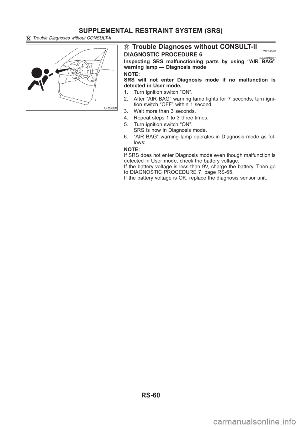
Trouble Diagnoses without CONSULT-II=NJRS0049DIAGNOSTIC PROCEDURE 6NJRS0049S01Inspecting SRS malfunctioning parts by using “AIR BAG”
warning lamp — Diagnosis mode
NOTE:
SRS will not enter Diagnosis mode if no malfunction is
detected in User mode.
1. Turn ignition switch “ON”.
2. After “AIR BAG” warning lamp lights for 7 seconds, turn igni-
tion switch “OFF” within 1 second.
3. Wait more than 3 seconds.
4. Repeat steps 1 to 3 three times.
5. Turn ignition switch “ON”.
SRS is now in Diagnosis mode.
6. “AIR BAG” warning lamp operates in Diagnosis mode as fol-
lows:
NOTE:
If SRS does not enter Diagnosis mode even though malfunction is
detected in User mode, check the battery voltage.
If the battery voltage is less than 9V, charge the battery. Then go
to DIAGNOSTIC PROCEDURE 7, page RS-65.
If the battery voltage is OK, replace the diagnosis sensor unit.
SUPPLEMENTAL RESTRAINT SYSTEM (SRS)
Trouble Diagnoses without CONSULT-II
RS-60
Page 3098 of 3189

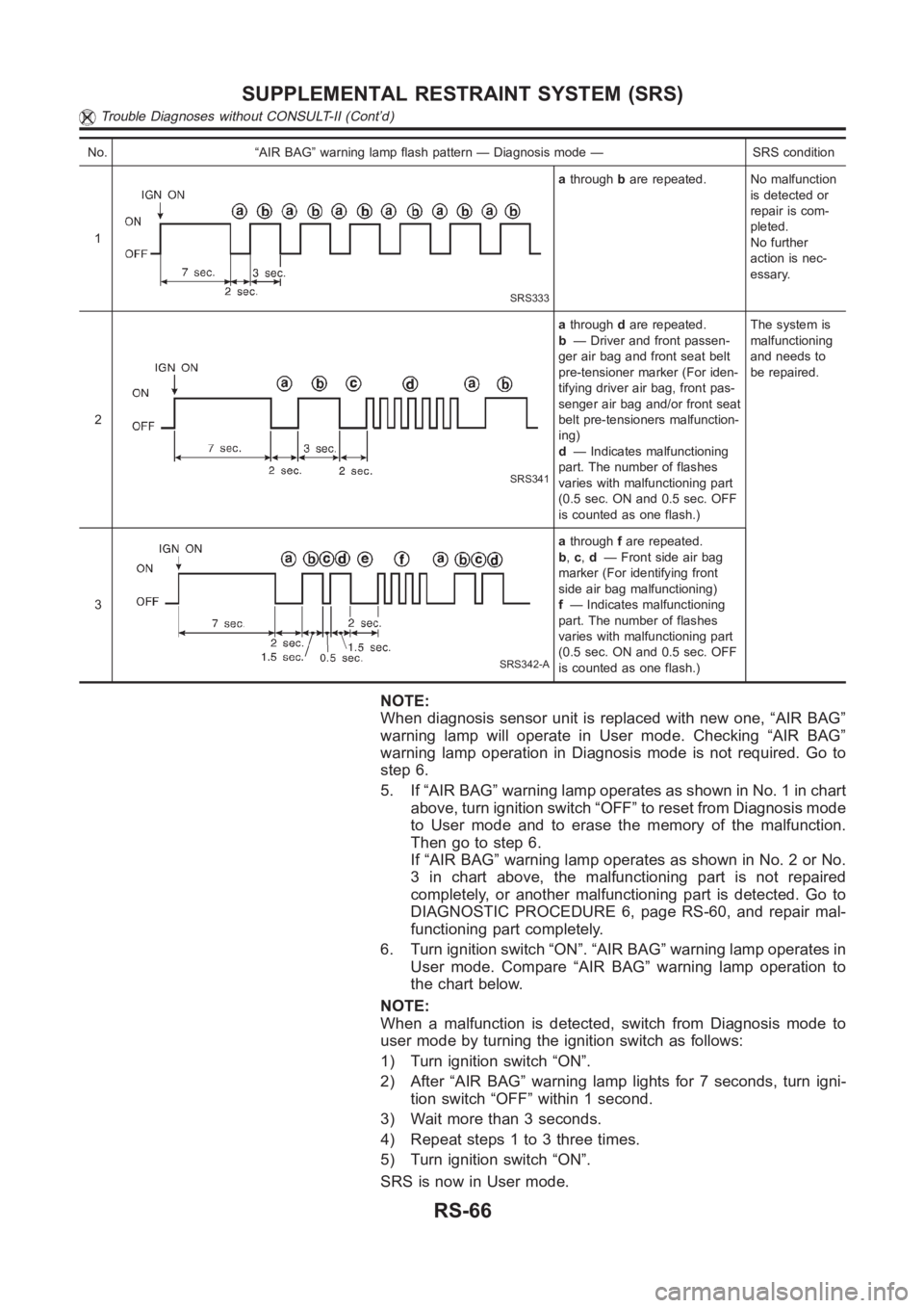
No. “AIR BAG” warning lamp flash pattern — Diagnosis mode — SRS condition
1
SRS333
athroughbare repeated. No malfunction
is detected or
repair is com-
pleted.
No further
action is nec-
essary.
2
SRS341
athroughdare repeated.
b— Driver and front passen-
ger air bag and front seat belt
pre-tensioner marker (For iden-
tifying driver air bag, front pas-
senger air bag and/or front seat
belt pre-tensioners malfunction-
ing)
d— Indicates malfunctioning
part. The number of flashes
varies with malfunctioning part
(0.5 sec. ON and 0.5 sec. OFF
is counted as one flash.)The system is
malfunctioning
and needs to
be repaired.
3
SRS342-A
athroughfare repeated.
b,c,d— Front side air bag
marker (For identifying front
side air bag malfunctioning)
f— Indicates malfunctioning
part. The number of flashes
varies with malfunctioning part
(0.5 sec. ON and 0.5 sec. OFF
is counted as one flash.)
NOTE:
When diagnosis sensor unit is replaced with new one, “AIR BAG”
warning lamp will operate in User mode. Checking “AIR BAG”
warning lamp operation in Diagnosis mode is not required. Go to
step 6.
5. If “AIR BAG” warning lamp operates as shown in No. 1 in chart
above, turn ignition switch “OFF” to reset from Diagnosis mode
to User mode and to erase the memory of the malfunction.
Then go to step 6.
If “AIR BAG” warning lamp operates as shown in No. 2 or No.
3 in chart above, the malfunctioning part is not repaired
completely, or another malfunctioning part is detected. Go to
DIAGNOSTIC PROCEDURE 6, page RS-60, and repair mal-
functioning part completely.
6. Turn ignition switch “ON”. “AIR BAG” warning lamp operates in
User mode. Compare “AIR BAG” warning lamp operation to
the chart below.
NOTE:
When a malfunction is detected, switch from Diagnosis mode to
user mode by turning the ignition switch as follows:
1) Turn ignition switch “ON”.
2) After “AIR BAG” warning lamp lights for 7 seconds, turn igni-
tion switch “OFF” within 1 second.
3) Wait more than 3 seconds.
4) Repeat steps 1 to 3 three times.
5) Turn ignition switch “ON”.
SRS is now in User mode.
SUPPLEMENTAL RESTRAINT SYSTEM (SRS)
Trouble Diagnoses without CONSULT-II (Cont’d)
RS-66