alternator NISSAN ALMERA TINO 2001 Service User Guide
[x] Cancel search | Manufacturer: NISSAN, Model Year: 2001, Model line: ALMERA TINO, Model: NISSAN ALMERA TINO 2001Pages: 3051, PDF Size: 46.38 MB
Page 2341 of 3051

SEM019G
1. Oil level gauge
2. Generator adjusting bar
3. A/C compressor bracket4. Alternator bracket
5. Water outlet
6. Cylinder block drain plug7. Exhaust manifold (With three way
catalyst)
8. Exhaust manifold cover
9. Heated oxygen sensor
OUTER COMPONENT PARTSSR
Removal and Installation (Cont'd)
EM-84
Page 2344 of 3051

Deflection adjustment Unit: mm (in) Tension adjustment* Unit: N (kg, lb)
Used belt
New beltUsed belt
New belt
LimitAfter adjust-
mentLimitAfter adjust-
ment
Alternator12-13
(0.47 - 0.51)8-9
(0.31 - 0.35)7-8
(0.28 - 0.31)264
(26.9, 59.3)493 - 583
(50.3 - 59.5,
110.8 - 131.1)11720 70J00 11720 70J05
603 - 691
(61.5 - 70.5,
135.6 -
155.3)652 - 740
(66.5 - 75.5,
146.6 - 166.4)
Air conditioner
compressor9 (0.35)5.5 - 6.5
(0.217 - 0.256)4.5 - 5.5
(0.177 -
0.217)304
(31.0, 68.3)534 - 623
(54.5 - 63.5,
120.0 - 140.1)11920 9F500 11920 9F505
652 - 740
(66.5 - 75.5,
146.6 -
166.4)838 - 926
(85.5 - 94.5,
188 - 208)
Power steering
oil pump12 (0.47)8-9
(0.31 - 0.35)7-8
(0.28 - 0.31)264
(26.9, 59.3)493 - 583
(50.3 - 59.5,
110.8 - 131.1)603 - 691
(61.5 - 70.5,
135.6 -
155.3)603 - 691
(61.5 - 70.5,
135.6 - 155.3)
Applied push-
ing force98 N (10 kg, 22 lb) Ð
*: If belt tension gauge cannot be installed at check points shown, check drive belt tension at a different location on the belt.
SMA328C
DRIVE BELTSSR
Checking (Cont'd)
EM-87
Page 2423 of 3051

JEM249G
InspectionNLEM0088+Before inspecting the engine, make sure the engine has
cooled down; wait approximately 30 minutes after the engine
has been stopped.
+Visually inspect all belts for wear, damage, or cracks on con-
tacting surfaces and edge areas.
+When measuring deflection, apply 98 N (10 kg, 22 lb) at the.
marked point.
+When checking belt deflection immediately after
installation, first adjust it to the specified value. Then,
after turning the crankshaft two turns or more, re-adjust to
the specified value to avoid variation in deflection
between pulleys.
+Tighten idler pulley lock nut by hand and measure deflec-
tion without looseness.
Belt Deflection:
Applied beltBelt specifica-
tionBelt deflection with 98 N (10 kg, 22 lb) force
applied* mm (in)
New AdjustedLimit for re-
tightening
Air conditioner
compressor
beltHA type low
edge belt4-5
(0.16 - 0.20)6-7
(0.24 - 0.28)8.5 (0.335)
Alternator &
water pump
beltHA type low-
edge wide
angle belt9.0 - 10.5
(0.354 -
0.413)11.0 - 12.5
(0.433 -
0.492)16.5 (0.650)
*: When engine is cold.
AdjustmentNLEM0089+Adjust belts with the parts shown below.
Applied belt Belt tightening method for adjustment
Air conditioner compressor belt Adjusting bolt on idler pulley
Alternator water pump belt Adjusting bolt on alternator
CAUTION:
+When a new belt is installed as a replacement, adjust it to
the value specified under ªNewº accommodations
because of insufficient adaptability with pulley grooves.
DRIVE BELTSYD
Inspection
EM-166
Page 2424 of 3051

+If the belt deflection of the current belt is out of the ªLimit
for re-tighteningº, adjust to the ªAdjusted valueº.
+When checking belt deflection immediately after
installation, first adjust it to the specified value. Then,
after turning crankshaft two turns or more, re-adjust it to
the specified value to avoid variation in deflection
between pulleys.
+Make sure the belts are fully fitted into the pulley grooves
during installation.
+Handle with care to avoid smearing the belts with oil or
cooling water etc.
+Do not twist or bend the belts with strong force.
JEM251G
AIR CONDITIONER COMPRESSOR BELTNLEM0089S011. Remove RH splash cover (with undercover attached).
2. Loosen idler pulley lock nut (A).
3. Turn adjusting bolt (B) to adjust.
+Refer to EM-166, ªInspectionº for adjustment values.
4. Tighten lock nut (A).
Nut A:
: 31 - 39 N´m (3.1 - 4.0 kg-m, 23 - 28 ft-lb)
ALTERNATOR & WATER PUMP BELTNLEM0089S021. Loosen adjuster lock nut (C).
2. Loosen alternator fixing bolts (D) (each on front and rear).
3. Turn adjusting bolt (E) to adjust.
+Refer to EM-166, ªInspectionº for adjustment values.
4. Tighten nut (C) and bolt (D) in this order.
Nut C:
: 19 - 24 N´m (1.9 - 2.5 kg-m, 14 - 18 ft-lb)
Bolt D:
: 44 - 57 N´m (4.4 - 5.9 kg-m, 32 - 42 ft-lb)
RemovalNLEM00901. Loosen each belt. Refer to EM-166, ªAdjustmentº.
2. Remove air conditioner compressor belt.
3. Remove alternator & water pump belt.
DRIVE BELTSYD
Adjustment (Cont'd)
EM-167
Page 2476 of 3051
crankshaft position sensor (TDC sensor) from the assem-
bly.
+Always pay extra attention not to damage edge of crank-
shaft position sensor (TDC sensor) or ring gear teeth.
REMOVALNLEM0069S011. Remove engine undercover, and hood for hoisting.
2. Drain coolant from both cylinder block and radiator. Refer to
LC-59, ªChanging Engine Coolantº.
3. Remove the following parts:
+Battery
+RH and LH front wheels
+RH and LH splash covers (combined with undercover)
+Auxiliary belts
+Alternator
+Alternator brackets
+Radiator and cooling fan
+Engine cover
+Air ducts and air cleaner case
LH side of engine room:
4. Disconnect all harnesses and grounds that are connected to
components on vehicle.
5. Disconnect vacuum hose on vacuum pump side.
6. Disconnect fuel feed and fuel return hoses on engine side.
+Immediately put blind plugs into the openings to prevent
fuel from flowing out.
7. Disconnect heater hose. Plug opening of hose to prevent cool-
ant from flowing out.
RH side of engine room:
8. Remove air conditioner compressor from brackets and move
it toward vehicle side. Secure compressor on vehicle side with
rope.
Vehicle underside:
9. Remove exhaust front tube.
10. Disconnect two hoses from power steering pump and plug to
stop fluid.
11. Remove M/T control rod and support rod.
12. Remove ABS wheel sensor, and temporarily hang brake cali-
per with rope on vehicle side.
13. Remove RH and LH drive shafts.
SEM499G
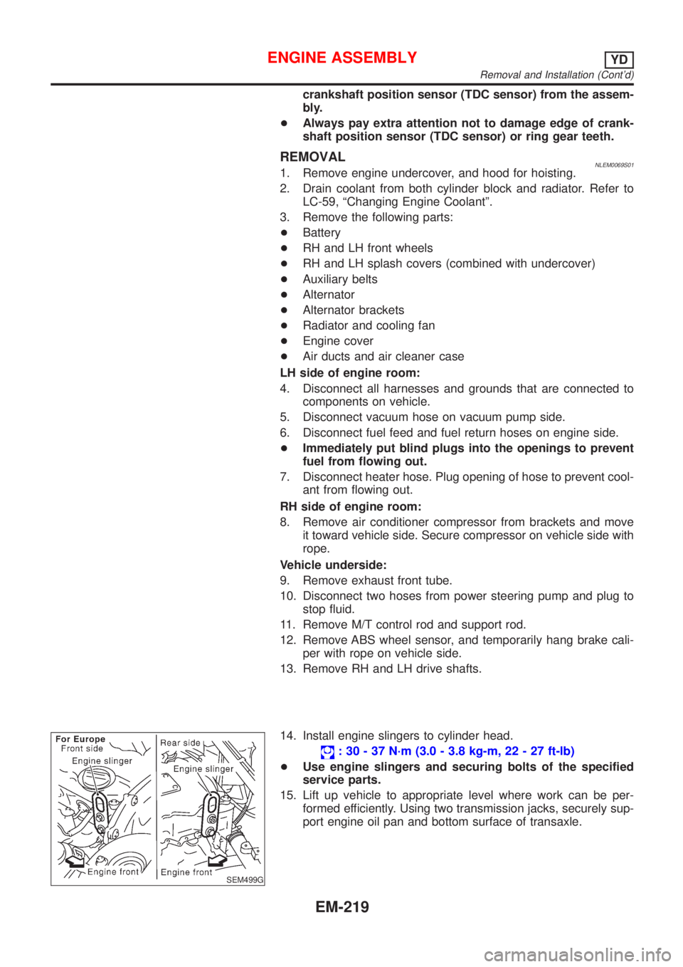
14. Install engine slingers to cylinder head.
: 30 - 37 N´m (3.0 - 3.8 kg-m, 22 - 27 ft-lb)
+Use engine slingers and securing bolts of the specified
service parts.
15. Lift up vehicle to appropriate level where work can be per-
formed efficiently. Using two transmission jacks, securely sup-
port engine oil pan and bottom surface of transaxle.
ENGINE ASSEMBLYYD
Removal and Installation (Cont'd)
EM-219
Page 2496 of 3051

JEM233G
16. Install rear oil seal retainer.
+Apply a continuous bead of specified liquid gasket (Refer to
EM-158, ªLiquid Gasket Application Procedureº.) on locations
shown in the figure.
JEM234G
17. Install pilot bushing.
+Force fit with the drift [approx. 19 mm (0.75 in) dia.].
SEM513G
18. Install fuel injection pump bracket.
+Install insulator according to the shape of the block, and secure
by placing the bracket against the insulator. (Not installed on
some models)
+Align the bracket with the dowel pins on the block to install.
+The two bolts used for dowel pins have a longer shanks than
the other two.
+Check the protruding distance of the dowel pin for fuel injec-
tion pump.
Standard: 13.0 - 15.0 mm (0.512 - 0.591 in)
19. Install parts to the engine in the reverse order of disassembly.
+Tighten bolts securing brackets of auxiliary components (A/C
compressor, alternator) to the specified torque.
: 57 - 65 N´m (5.8 - 6.7 kg-m, 42 - 48 ft-lb)
20. Remove engine from engine stand in the reverse order of
assembly.
21. Install flywheel.
+Holding ring gear with ring stopper (SST), tighten securing
bolts with TORX-socket (size: Q8 E20, Commercial Service
Tool).
+Tighten bolts uniformly in a crisscross manner.
SEM500G
REPLACEMENT OF PILOT BUSHINGNLEM0074S031. Remove pilot bushing using tool or suitable tool.
CYLINDER BLOCKYD
Assembly (Cont'd)
EM-239
Page 2498 of 3051
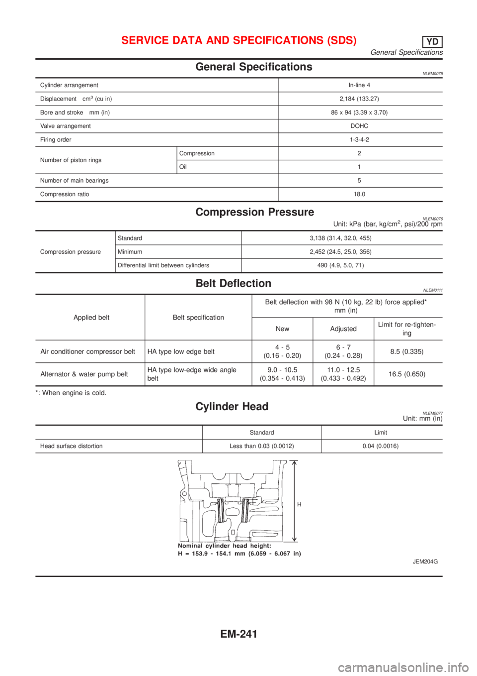
General SpecificationsNLEM0075
Cylinder arrangementIn-line 4
Displacement cm
3(cu in)2,184 (133.27)
Bore and stroke mm (in)86 x 94 (3.39 x 3.70)
Valve arrangementDOHC
Firing order1-3-4-2
Number of piston ringsCompression 2
Oil 1
Number of main bearings5
Compression ratio18.0
Compression PressureNLEM0076Unit: kPa (bar, kg/cm2, psi)/200 rpm
Compression pressureStandard 3,138 (31.4, 32.0, 455)
Minimum 2,452 (24.5, 25.0, 356)
Differential limit between cylinders 490 (4.9, 5.0, 71)
Belt DeflectionNLEM0111
Applied belt Belt specificationBelt deflection with 98 N (10 kg, 22 lb) force applied*
mm (in)
New AdjustedLimit for re-tighten-
ing
Air conditioner compressor belt HA type low edge belt4-5
(0.16 - 0.20)6-7
(0.24 - 0.28)8.5 (0.335)
Alternator & water pump beltHA type low-edge wide angle
belt9.0 - 10.5
(0.354 - 0.413)11.0 - 12.5
(0.433 - 0.492)16.5 (0.650)
*: When engine is cold.
Cylinder HeadNLEM0077Unit: mm (in)
Standard Limit
Head surface distortion Less than 0.03 (0.0012) 0.04 (0.0016)
JEM204G
SERVICE DATA AND SPECIFICATIONS (SDS)YD
General Specifications
EM-241
Page 2697 of 3051

A
A/C HFC134a (R134a) system precaution . HA-2
A/C HFC134a (R134a) system service
procedure .............................................. HA-85
A/C HFC134a (R134a) system service
tools ....................................................... HA-10
A/C HFC134a system service equip-
ment precaution ....................................... HA-6
A/C air flow ............................................... HA-19
A/C component layout .............................. HA-17
A/C compressor clutch removal and
installation .............................................. HA-90
A/C compressor precaution ........................ HA-5
A/C compressor special service tool .......... HA-9
A/C control linkage adjustment
(manual A/C) ......................................... HA-48
A/C control operation (manual A/C) .......... HA-18
A/C diagnostic work flow (manual
A/C) ...................................................... HA-40
A/C harness layout (manual A/C) ............. HA-21
A/C lubricant (R134a) ............................... HA-87
A/C operational check ............................... HA-41
A/C performance chart .............................. HA-78
A/C performance test diagnoses .............. HA-76
A/C relay ................................................... HA-73
A/C service data specification ................ HA-104
A/C switch ................................................. HA-74
A/C, M - Wiring diagram ........................... HA-27
A/CCUT - Wiring diagram ..................... EC-1301
A/T - Wiring diagram - AT - BA/FTS ........ AT-172
A/T - Wiring diagram - AT - ENG SS ........ AT-91,
177
A/T - Wiring diagram - AT - FTS ................ AT-75
A/T - Wiring diagram - AT - LPSV ... AT-101, 159
A/T - Wiring diagram - AT - MAIN ............. AT-62
A/T - Wiring diagram - AT - PNP/SW ........ AT-68
A/T - Wiring diagram - AT - SSV/A .......... AT-147
A/T - Wiring diagram - AT - TCV ....... AT-96, 166
A/T - Wiring diagram - AT - TPS ..... AT-106, 139
A/T - Wiring diagram - AT - VSS/AT .. AT-86, 128
A/T - Wiring diagram - AT -
VSSMTR .............................................. AT-134
A/T control ............................................. EC-1012
A/T diagnosis communication line .......... EC-928
A/T shift lock system - Wiring
diagram ................................................ AT-196
A/T shift lock system ................................ AT-195
A/T trouble diagnoses .......................... AT-41, 46
AAC/V - Wiring diagram . EC-345, 468, 865, 997
ABS (anti-lock brake system) ................... BR-42
ABS - Wiring diagram ............................... BR-48
ABS sensor rotor ....................................... AX-23
APS - Wiring diagram ........................... EC-1155
AT/C - Wiring diagram .......................... EC-1013
ATDIAG - Wiring diagram ....................... EC-929
Accelerator control system .................... FE-3, 14
Accelerator position sensor ................... EC-1155
Air bag disposal ........................................ RS-30Air bag precautions .................................. GI-3
Air bag ....................................................... RS-16
Air bleeding (hydraulic clutch) ................... CL-10
Air bleeding for brake system ..................... BR-8
Air conditioner cut control ....... EC-38, 572, 1081
Air flow meter - See Mass air flow
sensor ................................ EC-154, 679, 1143
Air mix door control linkage
adjustment ............................................. HA-50
Air spoiler, rear .......................................... BT-38
Alternator ................................................... SC-28
Angular tightening application ...... EM-5, 76, 158
Antenna - See Power antenna ................ EL-233
Anti-lock brake system - Wiring
diagram .................................................. BR-48
Audio and A/C control removal and
installation - See Instrument panel ........ BT-22
Audio ........................................................ EL-208
Automatic transaxle number ...................... GI-40
Auxiliary air control (AAC) valve .... EC-343, 466,
863, 995
B
Back-up lamp switch (M/T) ....................... MT-16
Back-up lamp ............................................. EL-93
Ball joint (front) .......................................... SU-13
Basic inspection ...................... EC-99, 623,1111
Battery ......................................................... SC-3
Baulk ring (M/T) .................................. MT-25, 63
Blower motor ............................................. HA-61
Blower resistor .......................................... HA-61
Board-on lift ................................................ GI-42
Body alignment .......................................... BT-65
Brake booster ............................................ BR-16
Brake fluid change ...................................... BR-7
Brake fluid level and line check .................. BR-7
Brake hydraulic line .................................... BR-9
Brake pedal ............................................... BR-11
Bulb specifications ................................... EL-524
Bumper, front .............................................. BT-7
Bumper, rear .............................................. BT-10
C
CHARGE - Wiring diagram ....................... SC-25
CHIME - Wiring diagram ......................... EL-166
CIGAR - Wiring diagram ......................... EL-195
CKPS - Wiring diagram . EC-297, 440, 821, 911,
970, 1166
CMPS - Wiring diagram .................. EC-304, 828
CONSULT for ABS .................................... BR-58
CONSULT for engine .............. EC-82, 607, 1102
COOL/F - Wiring diagram ..... EC-376, 885, 1201
Camshaft inspection ................. EM-36, 114, 204
Camshaft position sensor (CMPS) . EC-302, 825
Camshaft position sensor (PHASE) ........ EC-302
ALPHABETICAL INDEX
IDX-2
Page 2699 of 3051
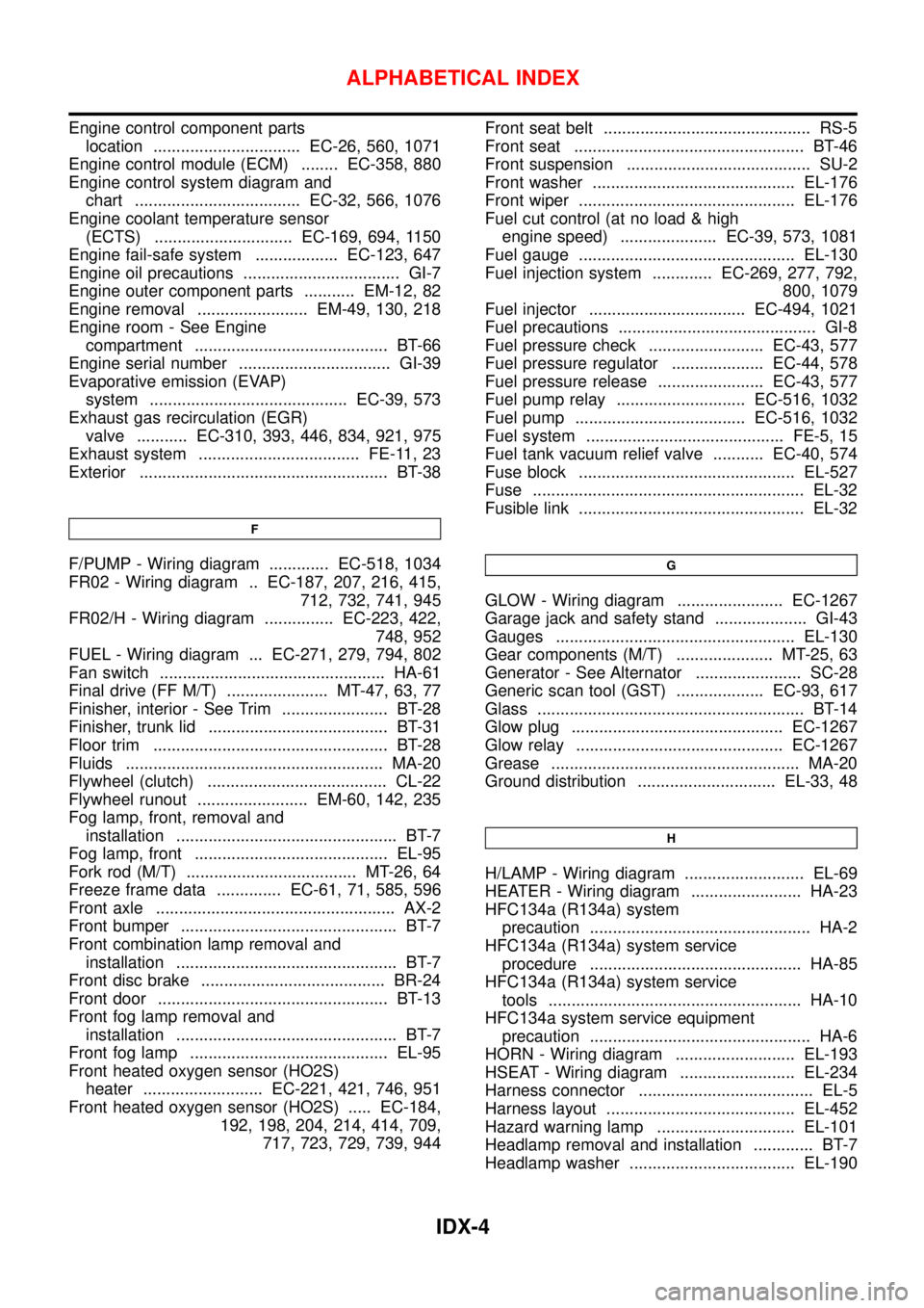
Engine control component parts
location ................................ EC-26, 560, 1071
Engine control module (ECM) ........ EC-358, 880
Engine control system diagram and
chart .................................... EC-32, 566, 1076
Engine coolant temperature sensor
(ECTS) .............................. EC-169, 694, 1150
Engine fail-safe system .................. EC-123, 647
Engine oil precautions .................................. GI-7
Engine outer component parts ........... EM-12, 82
Engine removal ........................ EM-49, 130, 218
Engine room - See Engine
compartment .......................................... BT-66
Engine serial number ................................. GI-39
Evaporative emission (EVAP)
system ........................................... EC-39, 573
Exhaust gas recirculation (EGR)
valve ........... EC-310, 393, 446, 834, 921, 975
Exhaust system ................................... FE-11, 23
Exterior ...................................................... BT-38
F
F/PUMP - Wiring diagram ............. EC-518, 1034
FR02 - Wiring diagram .. EC-187, 207, 216, 415,
712, 732, 741, 945
FR02/H - Wiring diagram ............... EC-223, 422,
748, 952
FUEL - Wiring diagram ... EC-271, 279, 794, 802
Fan switch ................................................. HA-61
Final drive (FF M/T) ...................... MT-47, 63, 77
Finisher, interior - See Trim ....................... BT-28
Finisher, trunk lid ....................................... BT-31
Floor trim ................................................... BT-28
Fluids ........................................................ MA-20
Flywheel (clutch) ....................................... CL-22
Flywheel runout ........................ EM-60, 142, 235
Fog lamp, front, removal and
installation ................................................ BT-7
Fog lamp, front .......................................... EL-95
Fork rod (M/T) ..................................... MT-26, 64
Freeze frame data .............. EC-61, 71, 585, 596
Front axle .................................................... AX-2
Front bumper ............................................... BT-7
Front combination lamp removal and
installation ................................................ BT-7
Front disc brake ........................................ BR-24
Front door .................................................. BT-13
Front fog lamp removal and
installation ................................................ BT-7
Front fog lamp ........................................... EL-95
Front heated oxygen sensor (HO2S)
heater .......................... EC-221, 421, 746, 951
Front heated oxygen sensor (HO2S) ..... EC-184,
192, 198, 204, 214, 414, 709,
717, 723, 729, 739, 944Front seat belt ............................................. RS-5
Front seat .................................................. BT-46
Front suspension ........................................ SU-2
Front washer ............................................ EL-176
Front wiper ............................................... EL-176
Fuel cut control (at no load & high
engine speed) ..................... EC-39, 573, 1081
Fuel gauge ............................................... EL-130
Fuel injection system ............. EC-269, 277, 792,
800, 1079
Fuel injector .................................. EC-494, 1021
Fuel precautions ........................................... GI-8
Fuel pressure check ......................... EC-43, 577
Fuel pressure regulator .................... EC-44, 578
Fuel pressure release ....................... EC-43, 577
Fuel pump relay ............................ EC-516, 1032
Fuel pump ..................................... EC-516, 1032
Fuel system ........................................... FE-5, 15
Fuel tank vacuum relief valve ........... EC-40, 574
Fuse block ............................................... EL-527
Fuse ........................................................... EL-32
Fusible link ................................................. EL-32G
GLOW - Wiring diagram ....................... EC-1267
Garage jack and safety stand .................... GI-43
Gauges .................................................... EL-130
Gear components (M/T) ..................... MT-25, 63
Generator - See Alternator ....................... SC-28
Generic scan tool (GST) ................... EC-93, 617
Glass .......................................................... BT-14
Glow plug .............................................. EC-1267
Glow relay ............................................. EC-1267
Grease ...................................................... MA-20
Ground distribution .............................. EL-33, 48
H
H/LAMP - Wiring diagram .......................... EL-69
HEATER - Wiring diagram ........................ HA-23
HFC134a (R134a) system
precaution ................................................ HA-2
HFC134a (R134a) system service
procedure .............................................. HA-85
HFC134a (R134a) system service
tools ....................................................... HA-10
HFC134a system service equipment
precaution ................................................ HA-6
HORN - Wiring diagram .......................... EL-193
HSEAT - Wiring diagram ......................... EL-234
Harness connector ...................................... EL-5
Harness layout ......................................... EL-452
Hazard warning lamp .............................. EL-101
Headlamp removal and installation ............. BT-7
Headlamp washer .................................... EL-190
ALPHABETICAL INDEX
IDX-4
Page 2962 of 3051
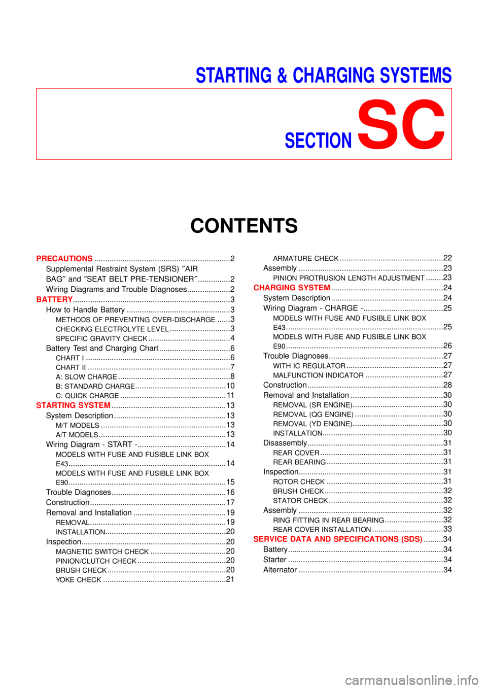
STARTING & CHARGING SYSTEMS
SECTION
SC
CONTENTS
PRECAUTIONS...............................................................2
Supplemental Restraint System (SRS)″AIR
BAG″and″SEAT BELT PRE-TENSIONER″...............2
Wiring Diagrams and Trouble Diagnoses....................2
BATTERY.........................................................................3
How to Handle Battery ................................................3
METHODS OF PREVENTING OVER-DISCHARGE......3
CHECKING ELECTROLYTE LEVEL............................3
SPECIFIC GRAVITY CHECK......................................4
Battery Test and Charging Chart .................................6
CHART I...................................................................6
CHART II..................................................................7
A: SLOW CHARGE....................................................8
B: STANDARD CHARGE..........................................10
C: QUICK CHARGE................................................. 11
STARTING SYSTEM.....................................................13
System Description ....................................................13
M/T MODELS..........................................................13
A/T MODELS...........................................................13
Wiring Diagram - START -.........................................14
MODELS WITH FUSE AND FUSIBLE LINK BOX
E43
.........................................................................14
MODELS WITH FUSE AND FUSIBLE LINK BOX
E90
.........................................................................15
Trouble Diagnoses.....................................................16
Construction ...............................................................17
Removal and Installation ...........................................19
REMOVAL...............................................................19
INSTALLATION........................................................20
Inspection...................................................................20
MAGNETIC SWITCH CHECK...................................20
PINION/CLUTCH CHECK.........................................20
BRUSH CHECK.......................................................20
YOKE CHECK.........................................................21
ARMATURE CHECK................................................22
Assembly ...................................................................23
PINION PROTRUSION LENGTH ADJUSTMENT........23
CHARGING SYSTEM....................................................24
System Description ....................................................24
Wiring Diagram - CHARGE -.....................................25
MODELS WITH FUSE AND FUSIBLE LINK BOX
E43
.........................................................................25
MODELS WITH FUSE AND FUSIBLE LINK BOX
E90
.........................................................................26
Trouble Diagnoses.....................................................27
WITH IC REGULATOR.............................................27
MALFUNCTION INDICATOR....................................27
Construction ...............................................................28
Removal and Installation ...........................................30
REMOVAL (SR ENGINE)..........................................30
REMOVAL (QG ENGINE).........................................30
REMOVAL (YD ENGINE)..........................................30
INSTALLATION........................................................30
Disassembly...............................................................31
REAR COVER.........................................................31
REAR BEARING......................................................31
Inspection...................................................................31
ROTOR CHECK......................................................31
BRUSH CHECK.......................................................32
STATOR CHECK.....................................................32
Assembly ...................................................................32
RING FITTING IN REAR BEARING...........................32
REAR COVER INSTALLATION.................................33
SERVICE DATA AND SPECIFICATIONS (SDS).........34
Battery........................................................................34
Starter ........................................................................34
Alternator ...................................................................34