Trim NISSAN ALMERA TINO 2001 Service Owner's Manual
[x] Cancel search | Manufacturer: NISSAN, Model Year: 2001, Model line: ALMERA TINO, Model: NISSAN ALMERA TINO 2001Pages: 3051, PDF Size: 46.38 MB
Page 388 of 3051

DRAIN HOSESNLBT0022S04
SBT005A
NBT151
1. Remove headlining to access drain hose connections. (Refer
to ªROOF TRIMº, BT-35, for detail.)
2. Check visually for proper connections, damage or deteriora-
tion.
(The figure shows only the front side.)
NBT152
3. If leakage occurs around luggage room, remove luggage room
side trim and check connecting area. Check for proper
connection, damage or tear.
4. Remove drain hoses and check visually for any damage,
cracks, or deterioration.
5. Pour water into drain hoses and find damaged portion.
+If any damaged portion is found at each step, replace the
damaged part.
WEATHERSTRIPNLBT0022S05+In the case of leakage around glass lid, close glass lid and pour
water over glass lid to find damaged or gap portion.
1. Remove glass lid assembly. (Refer to removal procedures,
BT-51, for details.)
2. Visually check weatherstrip for proper installation. If a gap
exists between glass lid and weatherstrip, check for sufficient
amount of butyl seal. If required, remove weatherstrip and
apply butyl seal.
Refer to ªEXTERIORº, BT-38, for details.
SUNROOF
Trouble Diagnoses (Cont'd)
BT-57
Page 461 of 3051
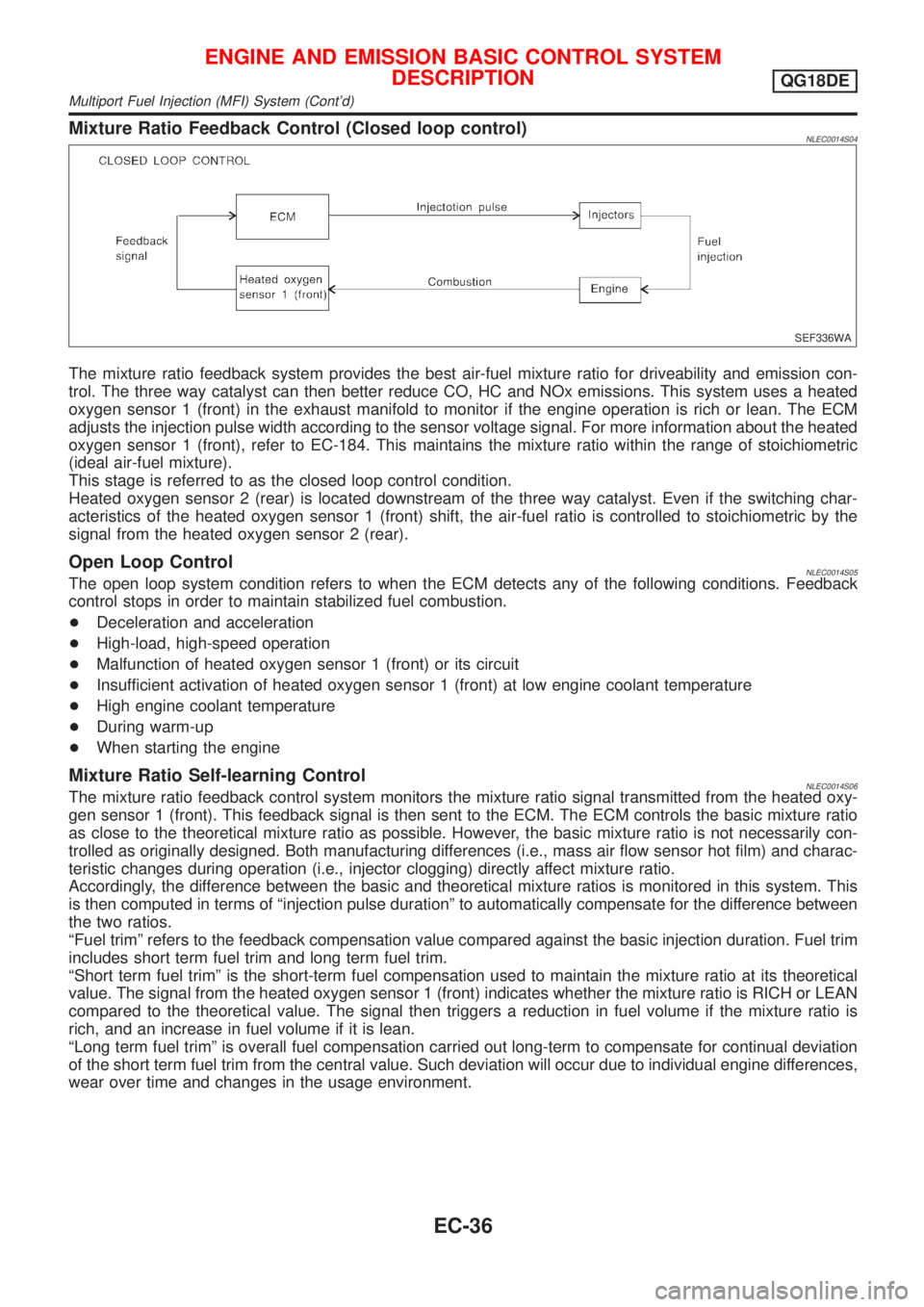
Mixture Ratio Feedback Control (Closed loop control)NLEC0014S04
SEF336WA
The mixture ratio feedback system provides the best air-fuel mixture ratio for driveability and emission con-
trol. The three way catalyst can then better reduce CO, HC and NOx emissions. This system uses a heated
oxygen sensor 1 (front) in the exhaust manifold to monitor if the engine operation is rich or lean. The ECM
adjusts the injection pulse width according to the sensor voltage signal. For more information about the heated
oxygen sensor 1 (front), refer to EC-184. This maintains the mixture ratio within the range of stoichiometric
(ideal air-fuel mixture).
This stage is referred to as the closed loop control condition.
Heated oxygen sensor 2 (rear) is located downstream of the three way catalyst. Even if the switching char-
acteristics of the heated oxygen sensor 1 (front) shift, the air-fuel ratio is controlled to stoichiometric by the
signal from the heated oxygen sensor 2 (rear).
Open Loop ControlNLEC0014S05The open loop system condition refers to when the ECM detects any of the following conditions. Feedback
control stops in order to maintain stabilized fuel combustion.
+Deceleration and acceleration
+High-load, high-speed operation
+Malfunction of heated oxygen sensor 1 (front) or its circuit
+Insufficient activation of heated oxygen sensor 1 (front) at low engine coolant temperature
+High engine coolant temperature
+During warm-up
+When starting the engine
Mixture Ratio Self-learning ControlNLEC0014S06The mixture ratio feedback control system monitors the mixture ratio signal transmitted from the heated oxy-
gen sensor 1 (front). This feedback signal is then sent to the ECM. The ECM controls the basic mixture ratio
as close to the theoretical mixture ratio as possible. However, the basic mixture ratio is not necessarily con-
trolled as originally designed. Both manufacturing differences (i.e., mass air flow sensor hot film) and charac-
teristic changes during operation (i.e., injector clogging) directly affect mixture ratio.
Accordingly, the difference between the basic and theoretical mixture ratios is monitored in this system. This
is then computed in terms of ªinjection pulse durationº to automatically compensate for the difference between
the two ratios.
ªFuel trimº refers to the feedback compensation value compared against the basic injection duration. Fuel trim
includes short term fuel trim and long term fuel trim.
ªShort term fuel trimº is the short-term fuel compensation used to maintain the mixture ratio at its theoretical
value. The signal from the heated oxygen sensor 1 (front) indicates whether the mixture ratio is RICH or LEAN
compared to the theoretical value. The signal then triggers a reduction in fuel volume if the mixture ratio is
rich, and an increase in fuel volume if it is lean.
ªLong term fuel trimº is overall fuel compensation carried out long-term to compensate for continual deviation
of the short term fuel trim from the central value. Such deviation will occur due to individual engine differences,
wear over time and changes in the usage environment.
ENGINE AND EMISSION BASIC CONTROL SYSTEM
DESCRIPTION
QG18DE
Multiport Fuel Injection (MFI) System (Cont'd)
EC-36
Page 486 of 3051

CONSULT-II or GST (Generic Scan Tool) Examples: P0340, P1320, P0705, P0750, etc.
These DTCs are prescribed by ISO 15031-6.
(CONSULT-II also displays the malfunctioning component or system.)
+1st trip DTC No. is the same as DTC No.
+Output of a DTC indicates a malfunction. However, Mode II and GST do not indicate whether the
malfunction is still occurring or has occurred in the past and has returned to normal.
CONSULT-II can identify malfunction status as shown below. Therefore, using CONSULT-II (if avail-
able) is recommended.
A sample of CONSULT-II display for DTC is shown below. DTC or 1st trip DTC of a malfunction is displayed
in SELF-DIAGNOSTIC RESULTS mode of CONSULT-II. Time data indicates how many times the vehicle was
driven after the last detection of a DTC.
If the DTC is being detected currently, the time data will be ª0º.
If a 1st trip DTC is stored in the ECM, the time data will be ª[1t]º.
SEF698X
Freeze Frame Data and 1st Trip Freeze Frame DataNLEC0031S0102The ECM records the driving conditions such as fuel system status, calculated load value, engine coolant
temperature, short term fuel trim, long term fuel trim, engine speed, vehicle speed, absolute throttle position,
base fuel schedule and intake air temperature at the moment a malfunction is detected.
Data which are stored in the ECM memory, along with the 1st trip DTC, are called 1st trip freeze frame data.
The data, stored together with the DTC data, are called freeze frame data and displayed on CONSULT-II or
GST. The 1st trip freeze frame data can only be displayed on the CONSULT-II screen, not on the GST. For
details, see EC-85.
Only one set of freeze frame data (either 1st trip freeze frame data or freeze frame data) can be stored in the
ECM. 1st trip freeze frame data is stored in the ECM memory along with the 1st trip DTC. There is no prior-
ity for 1st trip freeze frame data and it is updated each time a different 1st trip DTC is detected. However, once
freeze frame data (2nd trip detection/MI on) is stored in the ECM memory, 1st trip freeze frame data is no
longer stored. Remember, only one set of freeze frame data can be stored in the ECM. The ECM has the fol-
lowing priorities to update the data.
Priority Items
1Freeze frame data Misfire Ð DTC: P0300 - P0304 (0300 - 0304)
Fuel Injection System Function Ð DTC: P0171 (0171), P0172 (0172)
2 Except the above items
3 1st trip freeze frame data
For example, the EGR malfunction (Priority: 2) was detected and the freeze frame data was stored in the 2nd
trip. After that when the misfire (Priority: 1) is detected in another trip, the freeze frame data will be updated
from the EGR malfunction to the misfire. The 1st trip freeze frame data is updated each time a different mal-
function is detected. There is no priority for 1st trip freeze frame data. However, once freeze frame data is
stored in the ECM memory, 1st trip freeze data is no longer stored (because only one freeze frame data or
1st trip freeze frame data can be stored in the ECM). If freeze frame data is stored in the ECM memory and
freeze frame data with the same priority occurs later, the first (original) freeze frame data remains unchanged
in the ECM memory.
Both 1st trip freeze frame data and freeze frame data (along with the DTCs) are cleared when the ECM
memory is erased. Procedures for clearing the ECM memory are described in ªHow to Erase Emission-related
Diagnostic Informationº. Refer to EC-69.
ON BOARD DIAGNOSTIC SYSTEM DESCRIPTIONQG18DE
Emission-related Diagnostic Information (Cont'd)
EC-61
Page 496 of 3051

Procedures for clearing the DTC and the 1st trip DTC from the ECM memory are described in ªHow to Erase
Emission-related Diagnostic Informationº, EC-71.
When a (1st trip) DTC is detected, check, print out or write down and erase (1st trip) DTC and Freeze Frame
data as specified in ªWork Flowº procedure Step II, refer to EC-97. Then perform ªDTC Confirmation Proce-
dureº or ªOverall Function Checkº to try to duplicate the problem. If the malfunction is duplicated, the item
requires repair.
How to Read DTC and 1st Trip DTC
DTC and 1st trip DTC can be read by the following methods.
Without CONSULT-II
ECM displays the DTC by a set of four digit numbers with MI illumination in the diagnostic test mode II (Self-
diagnostic results). Example: 0100, 0115, 0340, 1335, etc.
With CONSULT-II
CONSULT-II displays the DTC in ªSELF-DIAG RESULTSº mode. Examples: P0100, P0115, P0340, P1335,
etc.
(CONSULT-II also displays the malfunctioning component or system.)
+1st trip DTC No. is the same as DTC No.
+Output of a DTC indicates a malfunction. However, ECM in the diagnostic test mode II (Self-diag-
nostic results) does not indicate whether the malfunction is still occurring or has occurred in the
past and has returned to normal. CONSULT-II can identify malfunction status as shown below.
Therefore, the use of CONSULT-II (if available) is recommended.
A sample CONSULT-II display for DTC and 1st trip DTC is shown below. DTC or 1st trip DTC of a malfunc-
tion is displayed in the SELF-DIAGNOSTIC RESULTS mode of CONSULT-II. Time data indicates how many
times the vehicle was driven after the last detection of a DTC.
If the DTC is being detected currently, the time data will be ª0º.
If a 1st trip DTC is stored in the ECM, the time data will be ª[1t]º.
SEF992X
Freeze Frame Data and 1st Trip Freeze Frame DataNLEC0031S0702The ECM records the driving conditions such as fuel system status, calculated load value, engine coolant
temperature, short term fuel trim, long term fuel trim, engine speed, vehicle speed, throttle valve opening, base
fuel schedule and intake air temperature at the moment a malfunction is detected.
Data which are stored in the ECM memory, along with the 1st trip DTC, are called 1st trip freeze frame data.
The data, stored together with the DTC data, are called freeze frame data and displayed on CONSULT-II. For
details, see EC-85.
Only one set of freeze frame data (either 1st trip freeze frame data or freeze frame data) can be stored in the
ECM. 1st trip freeze frame data is stored in the ECM memory along with the 1st trip DTC. There is no prior-
ity for 1st trip freeze frame data and it is updated each time a different 1st trip DTC is detected. However, once
freeze frame data is stored in the ECM memory, 1st trip freeze frame data is no longer stored. Remember,
only one set of freeze frame data can be stored in the ECM.
If freeze frame data is stored in the ECM memory and another freeze frame data occurs later, the first (origi-
nal) freeze frame data remains unchanged in the ECM memory.
Both 1st trip freeze frame data and freeze frame data (along with the DTCs) are cleared when the ECM
memory is erased. Procedures for clearing the ECM memory are described in ªHow to Erase Emission-related
Diagnostic Informationº, EC-71.
How to Erase Emission-related Diagnostic InformationNLEC0031S0706How to Erase DTC (With CONSULT-II)
1) If the ignition switch stays ªONº after repair work, be sure to turn ignition switch ªOFFº once. Wait at least
10 seconds and then turn it ªONº (engine stopped) again.
ON BOARD DIAGNOSTIC SYSTEM DESCRIPTIONQG18DE
Emission-related Diagnostic Information (Cont'd)
EC-71
Page 510 of 3051
2) 1st trip diagnostic trouble codes
3) Freeze frame data
4) 1st trip freeze frame data
5) System readiness test (SRT) codes
6) Test values
7) Distance traveled while MI is activated.
8) Others
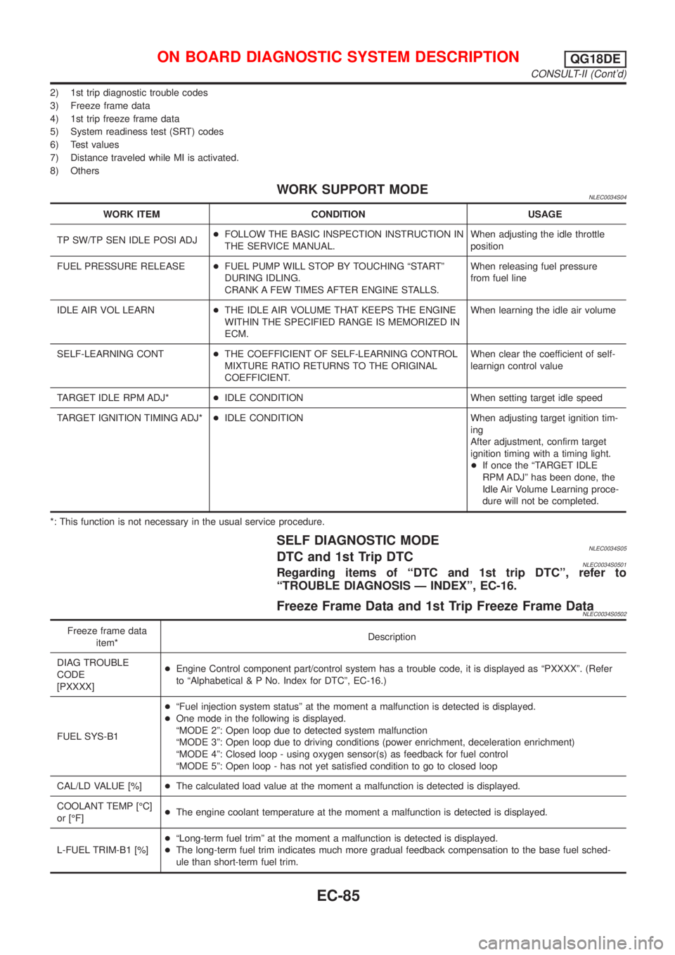
WORK SUPPORT MODENLEC0034S04
WORK ITEM CONDITION USAGE
TP SW/TP SEN IDLE POSI ADJ+FOLLOW THE BASIC INSPECTION INSTRUCTION IN
THE SERVICE MANUAL.When adjusting the idle throttle
position
FUEL PRESSURE RELEASE+FUEL PUMP WILL STOP BY TOUCHING ªSTARTº
DURING IDLING.
CRANK A FEW TIMES AFTER ENGINE STALLS.When releasing fuel pressure
from fuel line
IDLE AIR VOL LEARN+THE IDLE AIR VOLUME THAT KEEPS THE ENGINE
WITHIN THE SPECIFIED RANGE IS MEMORIZED IN
ECM.When learning the idle air volume
SELF-LEARNING CONT+THE COEFFICIENT OF SELF-LEARNING CONTROL
MIXTURE RATIO RETURNS TO THE ORIGINAL
COEFFICIENT.When clear the coefficient of self-
learnign control value
TARGET IDLE RPM ADJ*+IDLE CONDITION When setting target idle speed
TARGET IGNITION TIMING ADJ*+IDLE CONDITION When adjusting target ignition tim-
ing
After adjustment, confirm target
ignition timing with a timing light.
+If once the ªTARGET IDLE
RPM ADJº has been done, the
Idle Air Volume Learning proce-
dure will not be completed.
*: This function is not necessary in the usual service procedure.
SELF DIAGNOSTIC MODENLEC0034S05DTC and 1st Trip DTCNLEC0034S0501Regarding items of ªDTC and 1st trip DTCº, refer to
ªTROUBLE DIAGNOSIS Ð INDEXº, EC-16.
Freeze Frame Data and 1st Trip Freeze Frame DataNLEC0034S0502
Freeze frame data
item*Description
DIAG TROUBLE
CODE
[PXXXX]+Engine Control component part/control system has a trouble code, it is displayed as ªPXXXXº. (Refer
to ªAlphabetical & P No. Index for DTCº, EC-16.)
FUEL SYS-B1+ªFuel injection system statusº at the moment a malfunction is detected is displayed.
+One mode in the following is displayed.
ªMODE 2º: Open loop due to detected system malfunction
ªMODE 3º: Open loop due to driving conditions (power enrichment, deceleration enrichment)
ªMODE 4º: Closed loop - using oxygen sensor(s) as feedback for fuel control
ªMODE 5º: Open loop - has not yet satisfied condition to go to closed loop
CAL/LD VALUE [%]+The calculated load value at the moment a malfunction is detected is displayed.
COOLANT TEMP [ÉC]
or [ÉF]+The engine coolant temperature at the moment a malfunction is detected is displayed.
L-FUEL TRIM-B1 [%]+ªLong-term fuel trimº at the moment a malfunction is detected is displayed.
+The long-term fuel trim indicates much more gradual feedback compensation to the base fuel sched-
ule than short-term fuel trim.
ON BOARD DIAGNOSTIC SYSTEM DESCRIPTIONQG18DE
CONSULT-II (Cont'd)
EC-85
Page 511 of 3051

Freeze frame data
item*Description
S-FUEL TRIM-B1 [%]+ªShort-term fuel trimº at the moment a malfunction is detected is displayed.
+The short-term fuel trim indicates dynamic or instantaneous feedback compensation to the base fuel
schedule.
ENGINE SPEED [rpm]+The engine speed at the moment a malfunction is detected is displayed.
VEHICL SPEED [km/h]
or [mph]+The vehicle speed at the moment a malfunction is detected is displayed.
ABSOL TH´P/S [%]+The throttle valve opening angle at the moment a malfunction is detected is displayed.
B/FUEL SCHDL [msec]+The base fuel schedule at the moment a malfunction is detected is displayed.
INT/A TEMP SE [ÉC]
or [ÉF]+The intake air temperature at the moment a malfunction is detected is displayed.
*: The items are the same as those of 1st trip freeze frame data.
DATA MONITOR MODENLEC0034S06
Monitored item [Unit]ECM
input
signalsMain
signalsDescription Remarks
ENG SPEED [rpm]jj+Indicates the engine speed computed from
the POS signal of the crankshaft position
sensor.+Accuracy becomes poor if engine
speed drops below the idle rpm.
+If the signal is interrupted while the
engine is running, an abnormal
value may be indicated.
MAS A/F SE-B1 [V]jj+The signal voltage of the mass air flow sen-
sor is displayed.+When the engine is stopped, a cer-
tain value is indicated.
B/FUEL SCHDL
[msec]+ªBase fuel scheduleº indicates the fuel injec-
tion pulse width programmed into ECM, prior
to any learned on board correction.
A/F ALPHA-B1 [%]j+Indicates the mean value of the air-fuel ratio
feedback correction factor per cycle.+When the engine is stopped, a cer-
tain value is indicated.
+This data also includes the data for
the air-fuel ratio learning control.
COOLAN TEMP/S
[ÉC] or [ÉF]jj+The engine coolant temperature (determined
by the signal voltage of the engine coolant
temperature sensor) is displayed.+When the engine coolant tempera-
ture sensor is open or short-
circuited, ECM enters fail-safe
mode. The engine coolant tempera-
ture determined by the ECM is dis-
played.
HO2S1 (B1) [V]jj+The signal voltage of the heated oxygen sen-
sor 1 (front) is displayed.
HO2S2 (B1) [V]j+The signal voltage of the heated oxygen sen-
sor 2 (rear) is displayed.
HO2S1 MNTR (B1)
[RICH/LEAN]j+Display of heated oxygen sensor 1 (front)
signal during air-fuel ratio feedback control:
RICH ... means the mixture became ªrichº,
and control is being affected toward a leaner
mixture.
LEAN ... means the mixture became ªleanº,
and control is being affected toward a rich
mixture.+After turning ON the ignition switch,
ªRICHº is displayed until air-fuel mix-
ture ratio feedback control begins.
+When the air-fuel ratio feedback is
clamped, the value just before the
clamping is displayed continuously.
ON BOARD DIAGNOSTIC SYSTEM DESCRIPTIONQG18DE
CONSULT-II (Cont'd)
EC-86
Page 995 of 3051

Mixture Ratio Feedback Control (Closed loop control)NLEC1342S04
SEF336WA
The mixture ratio feedback system provides the best air-fuel mixture ratio for driveability and emission con-
trol. The three way catalyst can then better reduce CO, HC and NOx emissions. This system uses a heated
oxygen sensor 1 (front) in the exhaust manifold to monitor if the engine operation is rich or lean. The ECM
adjusts the injection pulse width according to the sensor voltage signal. For more information about the heated
oxygen sensor 1 (front), refer to EC-709. This maintains the mixture ratio within the range of stoichiometric
(ideal air-fuel mixture).
This stage is referred to as the closed loop control condition.
Heated oxygen sensor 2 (rear) is located downstream of the three way catalyst. Even if the switching char-
acteristics of the heated oxygen sensor 1 (front) shift, the air-fuel ratio is controlled to stoichiometric by the
signal from the heated oxygen sensor 2 (rear).
Open Loop ControlNLEC1342S05The open loop system condition refers to when the ECM detects any of the following conditions. Feedback
control stops in order to maintain stabilized fuel combustion.
+Deceleration and acceleration
+High-load, high-speed operation
+Malfunction of heated oxygen sensor 1 (front) or its circuit
+Insufficient activation of heated oxygen sensor 1 (front) at low engine coolant temperature
+High engine coolant temperature
+During warm-up
+When starting the engine
Mixture Ratio Self-learning ControlNLEC1342S06The mixture ratio feedback control system monitors the mixture ratio signal transmitted from the heated oxy-
gen sensor 1 (front). This feedback signal is then sent to the ECM. The ECM controls the basic mixture ratio
as close to the theoretical mixture ratio as possible. However, the basic mixture ratio is not necessarily con-
trolled as originally designed. Both manufacturing differences (i.e., mass air flow sensor hot film) and charac-
teristic changes during operation (i.e., injector clogging) directly affect mixture ratio.
Accordingly, the difference between the basic and theoretical mixture ratios is monitored in this system. This
is then computed in terms of ªinjection pulse durationº to automatically compensate for the difference between
the two ratios.
ªFuel trimº refers to the feedback compensation value compared against the basic injection duration. Fuel trim
includes short term fuel trim and long term fuel trim.
ªShort term fuel trimº is the short-term fuel compensation used to maintain the mixture ratio at its theoretical
value. The signal from the heated oxygen sensor 1 (front) indicates whether the mixture ratio is RICH or LEAN
compared to the theoretical value. The signal then triggers a reduction in fuel volume if the mixture ratio is
rich, and an increase in fuel volume if it is lean.
ªLong term fuel trimº is overall fuel compensation carried out long-term to compensate for continual deviation
of the short term fuel trim from the central value. Such deviation will occur due to individual engine differences,
wear over time and changes in the usage environment.
ENGINE AND EMISSION BASIC CONTROL SYSTEM
DESCRIPTION
SR20DE
Multiport Fuel Injection (MFI) System (Cont'd)
EC-570
Page 1010 of 3051

CONSULT-II or GST (Generic Scan Tool) Examples: P0340, P1320, P0705, P0750, etc.
These DTCs are prescribed by ISO 15031-6.
(CONSULT-II also displays the malfunctioning component or system.)
+1st trip DTC No. is the same as DTC No.
+Output of a DTC indicates a malfunction. However, Mode II and GST do not indicate whether the
malfunction is still occurring or has occurred in the past and has returned to normal.
CONSULT-II can identify malfunction status as shown below. Therefore, using CONSULT-II (if avail-
able) is recommended.
A sample of CONSULT-II display for DTC is shown below. DTC or 1st trip DTC of a malfunction is displayed
in SELF-DIAGNOSTIC RESULTS mode of CONSULT-II. Time data indicates how many times the vehicle was
driven after the last detection of a DTC.
If the DTC is being detected currently, the time data will be ª0º.
If a 1st trip DTC is stored in the ECM, the time data will be ª[1t]º.
SEF698X
Freeze Frame Data and 1st Trip Freeze Frame DataNLEC1361S0102The ECM records the driving conditions such as fuel system status, calculated load value, engine coolant
temperature, short term fuel trim, long term fuel trim, engine speed, vehicle speed, absolute throttle position,
base fuel schedule and intake air temperature at the moment a malfunction is detected.
Data which are stored in the ECM memory, along with the 1st trip DTC, are called 1st trip freeze frame data.
The data, stored together with the DTC data, are called freeze frame data and displayed on CONSULT-II or
GST. The 1st trip freeze frame data can only be displayed on the CONSULT-II screen, not on the GST. For
details, see EC-610.
Only one set of freeze frame data (either 1st trip freeze frame data or freeze frame data) can be stored in the
ECM. 1st trip freeze frame data is stored in the ECM memory along with the 1st trip DTC. There is no prior-
ity for 1st trip freeze frame data and it is updated each time a different 1st trip DTC is detected. However, once
freeze frame data (2nd trip detection/MI on) is stored in the ECM memory, 1st trip freeze frame data is no
longer stored. Remember, only one set of freeze frame data can be stored in the ECM. The ECM has the fol-
lowing priorities to update the data.
Priority Items
1Freeze frame data Misfire Ð DTC: P0300 - P0304 (0300 - 0304)
Fuel Injection System Function Ð DTC: P0171 (0171), P0172 (0172)
2 Except the above items (Includes CVT related items)
3 1st trip freeze frame data
For example, the EGR malfunction (Priority: 2) was detected and the freeze frame data was stored in the 2nd
trip. After that when the misfire (Priority: 1) is detected in another trip, the freeze frame data will be updated
from the EGR malfunction to the misfire. The 1st trip freeze frame data is updated each time a different mal-
function is detected. There is no priority for 1st trip freeze frame data. However, once freeze frame data is
stored in the ECM memory, 1st trip freeze data is no longer stored (because only one freeze frame data or
1st trip freeze frame data can be stored in the ECM). If freeze frame data is stored in the ECM memory and
freeze frame data with the same priority occurs later, the first (original) freeze frame data remains unchanged
in the ECM memory.
Both 1st trip freeze frame data and freeze frame data (along with the DTCs) are cleared when the ECM
memory is erased. Procedures for clearing the ECM memory are described in ªHow to Erase Emission-related
Diagnostic Informationº. Refer to EC-594.
ON BOARD DIAGNOSTIC SYSTEM DESCRIPTIONSR20DE
Emission-related Diagnostic Information (Cont'd)
EC-585
Page 1021 of 3051

+Output of a DTC indicates a malfunction. However, ECM in the diagnostic test mode II (Self-diag-
nostic results) does not indicate whether the malfunction is still occurring or has occurred in the
past and has returned to normal. CONSULT-II can identify malfunction status as shown below.
Therefore, the use of CONSULT-II (if available) is recommended.
A sample CONSULT-II display for DTC and 1st trip DTC is shown below. DTC or 1st trip DTC of a malfunc-
tion is displayed in the SELF-DIAGNOSTIC RESULTS mode of CONSULT-II. Time data indicates how many
times the vehicle was driven after the last detection of a DTC.
If the DTC is being detected currently, the time data will be ª0º.
If a 1st trip DTC is stored in the ECM, the time data will be ª[1t]º.
SEF992X
Freeze Frame Data and 1st Trip Freeze Frame DataNLEC1361S0202The ECM records the driving conditions such as fuel system status, calculated load value, engine coolant
temperature, short term fuel trim, long term fuel trim, engine speed, vehicle speed, throttle valve opening, base
fuel schedule and intake air temperature at the moment a malfunction is detected.
Data which are stored in the ECM memory, along with the 1st trip DTC, are called 1st trip freeze frame data.
The data, stored together with the DTC data, are called freeze frame data and displayed on CONSULT-II. For
details, see EC-610.
Only one set of freeze frame data (either 1st trip freeze frame data or freeze frame data) can be stored in the
ECM. 1st trip freeze frame data is stored in the ECM memory along with the 1st trip DTC. There is no prior-
ity for 1st trip freeze frame data and it is updated each time a different 1st trip DTC is detected. However, once
freeze frame data is stored in the ECM memory, 1st trip freeze frame data is no longer stored. Remember,
only one set of freeze frame data can be stored in the ECM.
If freeze frame data is stored in the ECM memory and another freeze frame data occurs later, the first (origi-
nal) freeze frame data remains unchanged in the ECM memory.
Both 1st trip freeze frame data and freeze frame data (along with the DTCs) are cleared when the ECM
memory is erased. Procedures for clearing the ECM memory are described in ªHow to Erase Emission-related
Diagnostic Informationº, EC-596.
How to Erase Emission-related Diagnostic InformationNLEC1361S0203How to Erase DTC (With CONSULT-II)
1) If the ignition switch stays ªONº after repair work, be sure to turn ignition switch ªOFFº once. Wait at least
10 seconds and then turn it ªONº (engine stopped) again.
2) Touch ªENGINEº.
3) Touch ªSELF-DIAG RESULTSº.
4) Touch ªERASEº. (The DTC in the ECM will be erased.)
ON BOARD DIAGNOSTIC SYSTEM DESCRIPTIONSR20DE
Emission-related Diagnostic Information (Cont'd)
EC-596
Page 1035 of 3051

7) Distance traveled while MI is activated.
8) Others
WORK SUPPORT MODENLEC1365S04
WORK ITEM CONDITION USAGE
TP SW/TP SEN IDLE POSI ADJ+FOLLOW THE BASIC INSPECTION INSTRUCTION IN
THE SERVICE MANUAL.When adjusting the idle throttle
position
IGNITION TIMING ADJ+IGNITION TIMING FEEDBACK CONTROL WILL BE
HELD BY TOUCHING ªSTARTº. AFTER DOING SO,
ADJUST IGNITION TIMING WITH A TIMING LIGHT
BY TURNING THE CAMSHAFT POSITION SENSOR.When adjusting initial ignition tim-
ing
FUEL PRESSURE RELEASE+FUEL PUMP WILL STOP BY TOUCHING ªSTARTº
DURING IDLING.
CRANK A FEW TIMES AFTER ENGINE STALLS.When releasing fuel pressure
from fuel line
IDLE AIR VOL LEARN+THE IDLE AIR VOLUME THAT KEEPS THE ENGINE
WITHIN THE SPECIFIED RANGE IS MEMORIZED IN
ECM.When learning the idle air volume
SELF-LEARNING CONT+THE COEFFICIENT OF SELF-LEARNING CONTROL
MIXTURE RATIO RETURNS TO THE ORIGINAL
COEFFICIENT.When clear the coefficient of self-
learning control value
TARGET IDLE RPM ADJ*+IDLE CONDITION When setting target idle speed
*: This function is not necessary in the usual service procedure.
SELF DIAGNOSTIC MODENLEC1365S05DTC and 1st Trip DTCNLEC1365S0501Regarding items of ªDTC and 1st trip DTCº, refer to
ªTROUBLE DIAGNOSIS Ð INDEXº, EC-550.
Freeze Frame Data and 1st Trip Freeze Frame DataNLEC1365S0502
Freeze frame data
item*Description
DIAG TROUBLE
CODE
[PXXXX]+Engine Control component part/control system has a trouble code, it is displayed as ªPXXXXº. (Refer
to ªAlphabetical & P No. Index for DTCº, EC-550.)
FUEL SYS-B1+ªFuel injection system statusº at the moment a malfunction is detected is displayed.
+One mode in the following is displayed.
ªMODE 2º: Open loop due to detected system malfunction
ªMODE 3º: Open loop due to driving conditions (power enrichment, deceleration enrichment)
ªMODE 4º: Closed loop - using oxygen sensor(s) as feedback for fuel control
ªMODE 5º: Open loop - has not yet satisfied condition to go to closed loop
CAL/LD VALUE [%]+The calculated load value at the moment a malfunction is detected is displayed.
COOLANT TEMP [ÉC]
or [ÉF]+The engine coolant temperature at the moment a malfunction is detected is displayed.
L-FUEL TRIM-B1 [%]+ªLong-term fuel trimº at the moment a malfunction is detected is displayed.
+The long-term fuel trim indicates much more gradual feedback compensation to the base fuel sched-
ule than short-term fuel trim.
S-FUEL TRIM-B1 [%]+ªShort-term fuel trimº at the moment a malfunction is detected is displayed.
+The short-term fuel trim indicates dynamic or instantaneous feedback compensation to the base fuel
schedule.
ENGINE SPEED [rpm]+The engine speed at the moment a malfunction is detected is displayed.
VEHICL SPEED [km/h]
or [mph]+The vehicle speed at the moment a malfunction is detected is displayed.
ABSOL TH´P/S [%]+The throttle valve opening angle at the moment a malfunction is detected is displayed.
ON BOARD DIAGNOSTIC SYSTEM DESCRIPTIONSR20DE
CONSULT-II (Cont'd)
EC-610