fuel pump NISSAN ALMERA TINO 2001 Service Owner's Manual
[x] Cancel search | Manufacturer: NISSAN, Model Year: 2001, Model line: ALMERA TINO, Model: NISSAN ALMERA TINO 2001Pages: 3051, PDF Size: 46.38 MB
Page 944 of 3051
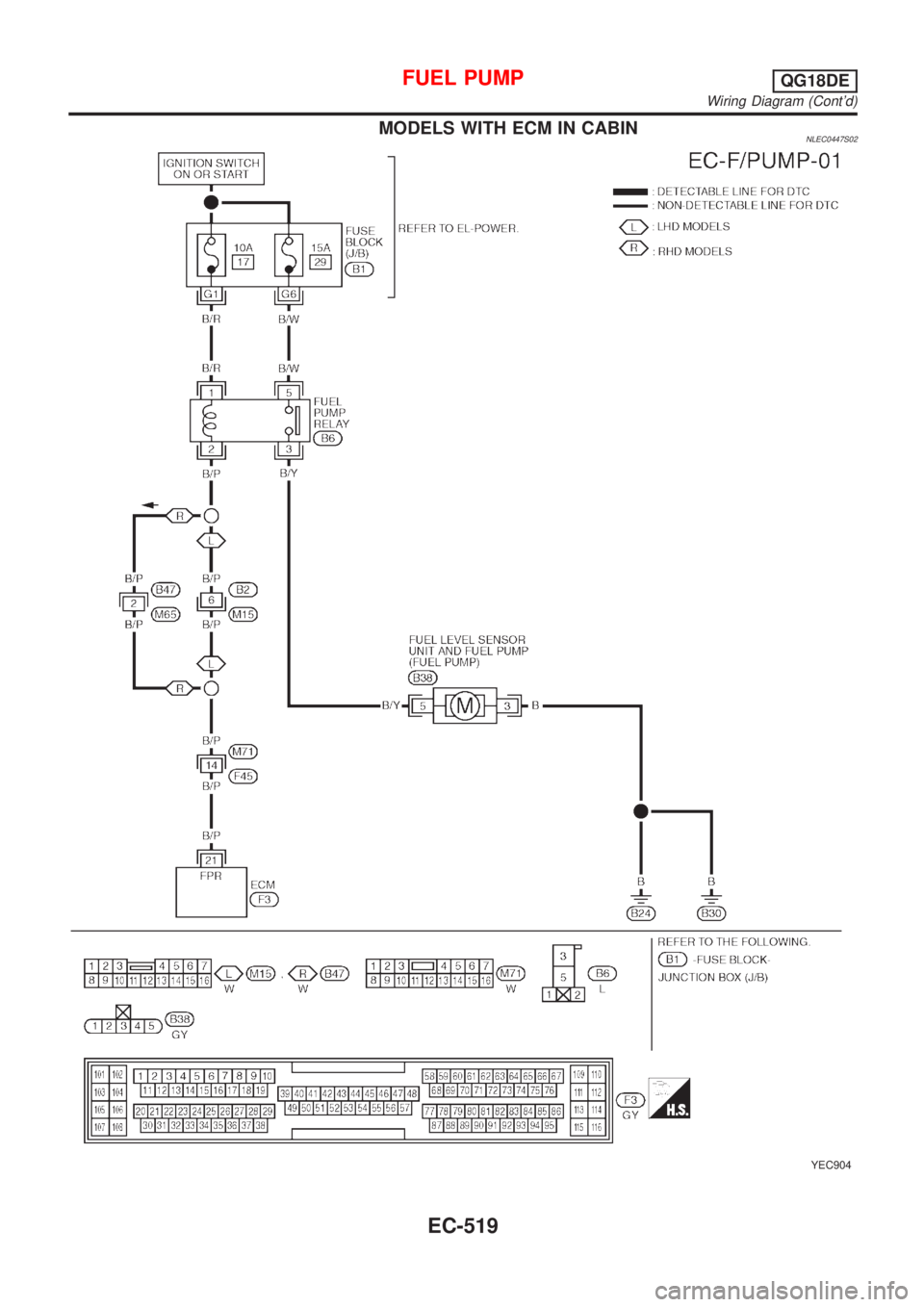
MODELS WITH ECM IN CABINNLEC0447S02
YEC904
FUEL PUMPQG18DE
Wiring Diagram (Cont'd)
EC-519
Page 945 of 3051
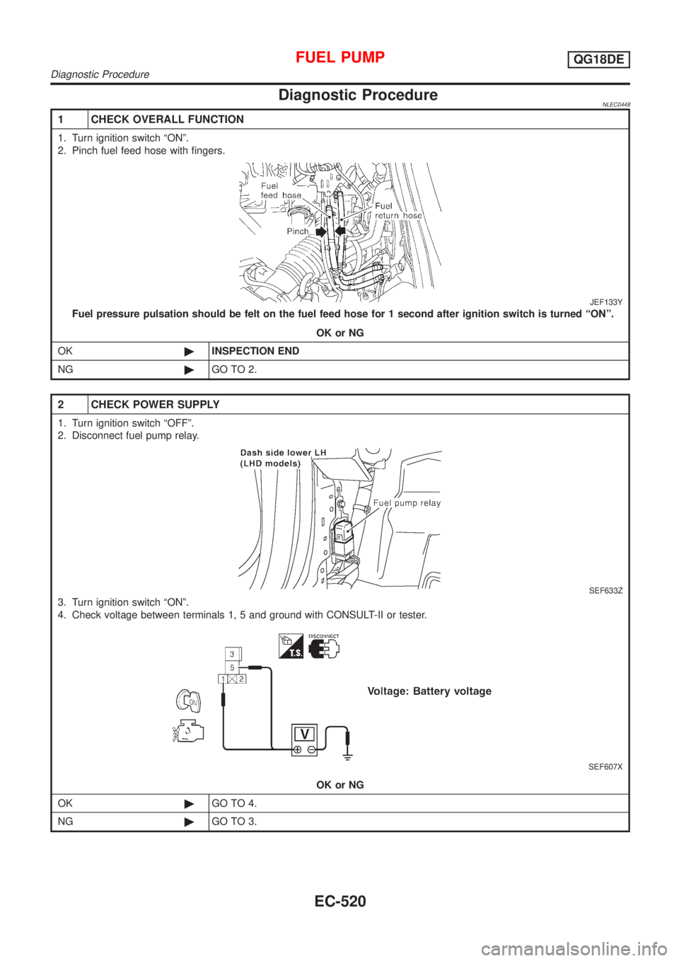
Diagnostic ProcedureNLEC0448
1 CHECK OVERALL FUNCTION
1. Turn ignition switch ªONº.
2. Pinch fuel feed hose with fingers.
JEF133Y
Fuel pressure pulsation should be felt on the fuel feed hose for 1 second after ignition switch is turned ªONº.
OK or NG
OK©INSPECTION END
NG©GO TO 2.
2 CHECK POWER SUPPLY
1. Turn ignition switch ªOFFº.
2. Disconnect fuel pump relay.
SEF633Z
3. Turn ignition switch ªONº.
4. Check voltage between terminals 1, 5 and ground with CONSULT-II or tester.
SEF607X
OK or NG
OK©GO TO 4.
NG©GO TO 3.
FUEL PUMPQG18DE
Diagnostic Procedure
EC-520
Page 946 of 3051
3 DETECT MALFUNCTIONING PART
Check the following.
+10A fuse
+15A fuse
+Harness for open or short between fuse and fuel pump relay
©Repair harness or connectors.
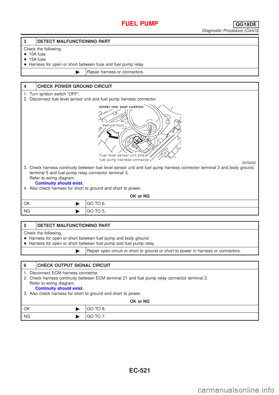
4 CHECK POWER GROUND CIRCUIT
1. Turn ignition switch ªOFFº.
2. Disconnect fuel level sensor unit and fuel pump harness connector.
SEF632Z
3. Check harness continuity between fuel level sensor unit and fuel pump harness connector terminal 3 and body ground,
terminal 5 and fuel pump relay connector terminal 3.
Refer to wiring diagram.
Continuity should exist.
4. Also check harness for short to ground and short to power.
OK or NG
OK©GO TO 6.
NG©GO TO 5.
5 DETECT MALFUNCTIONING PART
Check the following.
+Harness for open or short between fuel pump and body ground
+Harness for open or short between fuel pump and fuel pump relay
©Repair open circuit or short to ground or short to power in harness or connectors.
6 CHECK OUTPUT SIGNAL CIRCUIT
1. Disconnect ECM harness connector.
2. Check harness continuity between ECM terminal 21 and fuel pump relay connector terminal 2.
Refer to wiring diagram.
Continuity should exist.
3. Also check harness for short to ground and short to power.
OK or NG
OK©GO TO 8.
NG©GO TO 7.
FUEL PUMPQG18DE
Diagnostic Procedure (Cont'd)
EC-521
Page 947 of 3051
7 DETECT MALFUNCTIONING PART
Check the following.
+Harness connectors B2, M15 (LHD models), B47, M65 (RHD models)
+Harness connectors M49, F43 (where fitted)
+Harness connectors M71, F45 (where fitted)
+Harness for open or short between ECM and fuel pump relay
NG©Repair open circuit or short to ground or short to power in harness or connectors.
8 CHECK FUEL PUMP RELAY
Refer to ªComponent Inspectionº, EC-522.
OK or NG
OK©GO TO 9.
NG©Replace fuel pump relay.
9 CHECK FUEL PUMP
Refer to ªComponent Inspectionº, EC-522.
OK or NG
OK©GO TO 10.
NG©Replace fuel pump.
10 CHECK INTERMITTENT INCIDENT
Perform ªTROUBLE DIAGNOSIS FOR INTERMITTENT INCIDENTº, EC-145.
©INSPECTION END
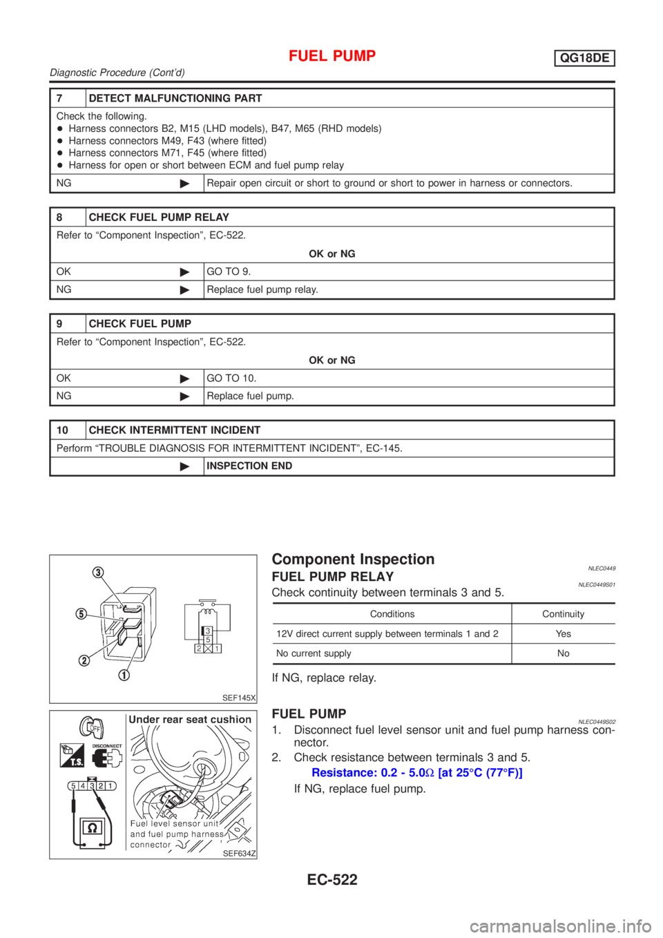
SEF145X
Component InspectionNLEC0449FUEL PUMP RELAYNLEC0449S01Check continuity between terminals 3 and 5.
Conditions Continuity
12V direct current supply between terminals 1 and 2 Yes
No current supply No
If NG, replace relay.
SEF634Z
FUEL PUMPNLEC0449S021. Disconnect fuel level sensor unit and fuel pump harness con-
nector.
2. Check resistance between terminals 3 and 5.
Resistance: 0.2 - 5.0W[at 25ÉC (77ÉF)]
If NG, replace fuel pump.
FUEL PUMPQG18DE
Diagnostic Procedure (Cont'd)
EC-522
Page 973 of 3051

EGR Volume Control Valve (where fitted)NLEC0560
Terminal No. ResistanceW[at 20ÉC (68ÉF)]
1-2
20-24 2-3
4-5
5-6
EGR Temperature Sensor (where fitted)NLEC0472
EGR temperature
ÉC (ÉF)Voltage
VResistance
MW
0 (32) 4.56 0.62 - 1.05
50 (122) 2.25 0.065 - 0.094
100 (212) 0.59 0.011 - 0.015
EVAP Canister Purge Volume Control ValveNLEC0481
Resistance [at 20ÉC (68ÉF)]W31-35
IACV-AAC ValveNLEC0474
Terminal No. ResistanceW[at 20ÉC (68ÉF)]
1-2
20-24 2-3
4-5
5-6
InjectorNLEC0475
Resistance [at 25ÉC (77ÉF)]W13.5 - 17.5
Ignition Coil with Power TransistorNLEC0561
Terminal No. (Polarity) ResistanceW[at 25ÉC (77ÉF)]
3 (+) - 2 (þ) Except 0 or¥
1 (+) - 3 (þ)
Except 0
1 (+) - 2 (þ)
CondenserNLEC0587
Resistance [at 25ÉC (77ÉF)] MWAbove 1
Fuel PumpNLEC0473
Resistance [at 25ÉC (77ÉF)]W0.2 - 5.0
SERVICE DATA AND SPECIFICATIONS (SDS)QG18DE
EGR Volume Control Valve (where fitted)
EC-548
Page 993 of 3051
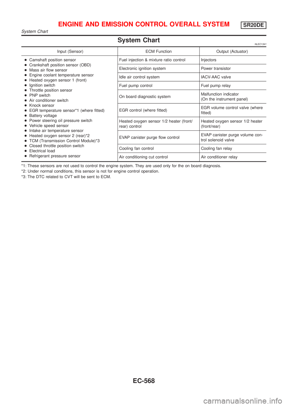
System ChartNLEC1341
Input (Sensor) ECM Function Output (Actuator)
+Camshaft position sensor
+Crankshaft position sensor (OBD)
+Mass air flow sensor
+Engine coolant temperature sensor
+Heated oxygen sensor 1 (front)
+Ignition switch
+Throttle position sensor
+PNP switch
+Air conditioner switch
+Knock sensor
+EGR temperature sensor*1 (where fitted)
+Battery voltage
+Power steering oil pressure switch
+Vehicle speed sensor
+Intake air temperature sensor
+Heated oxygen sensor 2 (rear)*2
+TCM (Transmission Control Module)*3
+Closed throttle position switch
+Electrical load
+Refrigerant pressure sensorFuel injection & mixture ratio control Injectors
Electronic ignition system Power transistor
Idle air control system IACV-AAC valve
Fuel pump control Fuel pump relay
On board diagnostic systemMalfunction indicator
(On the instrument panel)
EGR control (where fitted)EGR volume control valve (where
fitted)
Heated oxygen sensor 1/2 heater (front/
rear) controlHeated oxygen sensor 1/2 heater
(front/rear)
EVAP canister purge flow controlEVAP canister purge volume con-
trol solenoid valve
Cooling fan control Cooling fan relay
Air conditioning cut control Air conditioner relay
*1: These sensors are not used to control the engine system. They are used only for the on board diagnosis.
*2: Under normal conditions, this sensor is not for engine control operation.
*3: The DTC related to CVT will be sent to ECM.
ENGINE AND EMISSION CONTROL OVERALL SYSTEMSR20DE
System Chart
EC-568
Page 1002 of 3051

SEF094Y
SEF214Y
Fuel Pressure ReleaseNLEC1351Before disconnecting fuel line, release fuel pressure from fuel
line to eliminate danger.
WITH CONSULT-IINLEC1351S011. Start engine.
2. Perform ªFUEL PRESSURE RELEASEº in ªWORK SUP-
PORTº mode with CONSULT-II.
3. After engine stalls, crank it two or three times to release all fuel
pressure.
4. Turn ignition switch OFF.
JEF086Y
WITHOUT CONSULT-IINLEC1351S021. Remove fuse for fuel pump. Refer to fuse block cover for fuse
location.
2. Start engine.
3. After engine stalls, crank it two or three times to release all fuel
pressure.
4. Turn ignition switch OFF and reconnect fuel pump fuse.
SEF775Z
Fuel Pressure CheckNLEC1352+When reconnecting fuel line, always use new clamps.
+Make sure that clamp screw does not contact adjacent
parts.
+Use a torque driver to tighten clamps.
+Use Pressure Gauge to check fuel pressure.
+Do not perform fuel pressure check with system operat-
ing. Fuel pressure gauge may indicate false readings.
1. Release fuel pressure to zero.
2. Disconnect fuel hose from fuel feed tube (engine side).
3. Install pressure gauge between fuel hose and fuel feed tube.
4. Start engine and check for fuel leakage.
5. Read the indication of fuel pressure gauge.
At idle speed:
With vacuum hose connected
Approximately 235 kPa (2.35 bar, 2.4 kg/cm
2,34
psi)
With vacuum hose disconnected
Approximately 294 kPa (2.94 bar, 3.0 kg/cm
2,43
psi)
BASIC SERVICE PROCEDURESR20DE
Fuel Pressure Release
EC-577
Page 1034 of 3051

ItemDIAGNOSTIC TEST MODE
WORK
SUP-
PORTSELF-DIAGNOSTIC
RESULTS
D ATA
MONI-
TORD ATA
MONI-
TOR
(SPEC)ACTIVE
TESTDTC & SRT
CONFIRMATION
DTC*1FREEZE
FRAME
DATA*2SRT
STA-
TUSDTC
WORK
SUP-
PORT
ENGINE CONTROL COMPONENT PARTS
OUT-
PUTInjectors X X X
Power transistor (Ignition
timing)X*3
(misfire)XXX
IACV-AAC valve X X*3 X X X
EVAP canister purge volume
control solenoid valveX*3 X X X
Air conditioner relay X X
Fuel pump relay X X X X
EGR volume control valve
(where fitted)X X X X X*3
Heated oxygen sensor 1
heater (front)X*3 X X X*3
Heated oxygen sensor 2
heater (rear)X*3 X X X*3
Cooling fan X X X X
Calculated load value X X X
X: Applicable
*1: This item includes 1st trip DTCs.
*2: This mode includes 1st trip freeze frame data or freeze frame data. The items appear on CONSULT-II screen in freeze frame data
mode only if a 1st trip DTC or DTC is detected. For details, refer to EC-585, EC-596.
*3: Not applicable for models without Euro-OBD system
FUNCTIONNLEC1365S03
Diagnostic test mode Function
Work supportThis mode enables a technician to adjust some devices faster and more accurately by following the
indications on the CONSULT-II unit.
Self-diagnostic resultsSelf-diagnostic results such as 1st trip DTC, DTCs and 1st trip freeze frame data or freeze frame
data can be read and erased quickly.*1
Data monitor Input/Output data in the ECM can be read.
Data monitor (spec)Input/Output specifications of the basic fuel schedule, AFM, A/F feedback control value and the
other data monitor items can be read.
Active testDiagnostic Test Mode in which CONSULT-II drives some actuators apart from the ECMs and also
shifts some parameters in a specified range.
DTC and SRT confirmation The status of system monitoring tests and the self-diagnosis status/result can be confirmed.
ECM part number ECM part numbers can be read.
*1 The following emission-related diagnostic information is cleared when the ECM memory is erased.
1) Diagnostic trouble codes
2) 1st trip diagnostic trouble codes
3) Freeze frame data
4) 1st trip freeze frame data
5) System readiness test (SRT) codes
6) Test values
ON BOARD DIAGNOSTIC SYSTEM DESCRIPTIONSR20DE
CONSULT-II (Cont'd)
EC-609
Page 1035 of 3051

7) Distance traveled while MI is activated.
8) Others
WORK SUPPORT MODENLEC1365S04
WORK ITEM CONDITION USAGE
TP SW/TP SEN IDLE POSI ADJ+FOLLOW THE BASIC INSPECTION INSTRUCTION IN
THE SERVICE MANUAL.When adjusting the idle throttle
position
IGNITION TIMING ADJ+IGNITION TIMING FEEDBACK CONTROL WILL BE
HELD BY TOUCHING ªSTARTº. AFTER DOING SO,
ADJUST IGNITION TIMING WITH A TIMING LIGHT
BY TURNING THE CAMSHAFT POSITION SENSOR.When adjusting initial ignition tim-
ing
FUEL PRESSURE RELEASE+FUEL PUMP WILL STOP BY TOUCHING ªSTARTº
DURING IDLING.
CRANK A FEW TIMES AFTER ENGINE STALLS.When releasing fuel pressure
from fuel line
IDLE AIR VOL LEARN+THE IDLE AIR VOLUME THAT KEEPS THE ENGINE
WITHIN THE SPECIFIED RANGE IS MEMORIZED IN
ECM.When learning the idle air volume
SELF-LEARNING CONT+THE COEFFICIENT OF SELF-LEARNING CONTROL
MIXTURE RATIO RETURNS TO THE ORIGINAL
COEFFICIENT.When clear the coefficient of self-
learning control value
TARGET IDLE RPM ADJ*+IDLE CONDITION When setting target idle speed
*: This function is not necessary in the usual service procedure.
SELF DIAGNOSTIC MODENLEC1365S05DTC and 1st Trip DTCNLEC1365S0501Regarding items of ªDTC and 1st trip DTCº, refer to
ªTROUBLE DIAGNOSIS Ð INDEXº, EC-550.
Freeze Frame Data and 1st Trip Freeze Frame DataNLEC1365S0502
Freeze frame data
item*Description
DIAG TROUBLE
CODE
[PXXXX]+Engine Control component part/control system has a trouble code, it is displayed as ªPXXXXº. (Refer
to ªAlphabetical & P No. Index for DTCº, EC-550.)
FUEL SYS-B1+ªFuel injection system statusº at the moment a malfunction is detected is displayed.
+One mode in the following is displayed.
ªMODE 2º: Open loop due to detected system malfunction
ªMODE 3º: Open loop due to driving conditions (power enrichment, deceleration enrichment)
ªMODE 4º: Closed loop - using oxygen sensor(s) as feedback for fuel control
ªMODE 5º: Open loop - has not yet satisfied condition to go to closed loop
CAL/LD VALUE [%]+The calculated load value at the moment a malfunction is detected is displayed.
COOLANT TEMP [ÉC]
or [ÉF]+The engine coolant temperature at the moment a malfunction is detected is displayed.
L-FUEL TRIM-B1 [%]+ªLong-term fuel trimº at the moment a malfunction is detected is displayed.
+The long-term fuel trim indicates much more gradual feedback compensation to the base fuel sched-
ule than short-term fuel trim.
S-FUEL TRIM-B1 [%]+ªShort-term fuel trimº at the moment a malfunction is detected is displayed.
+The short-term fuel trim indicates dynamic or instantaneous feedback compensation to the base fuel
schedule.
ENGINE SPEED [rpm]+The engine speed at the moment a malfunction is detected is displayed.
VEHICL SPEED [km/h]
or [mph]+The vehicle speed at the moment a malfunction is detected is displayed.
ABSOL TH´P/S [%]+The throttle valve opening angle at the moment a malfunction is detected is displayed.
ON BOARD DIAGNOSTIC SYSTEM DESCRIPTIONSR20DE
CONSULT-II (Cont'd)
EC-610
Page 1038 of 3051

Monitored item [Unit]ECM
input
signalsMain
signalsDescription Remarks
EGR VOL CON/V
[step] (where fitted)j+Indicates the EGR volume control valve com-
puted by the ECM according to the input sig-
nals.
+The opening becomes larger as the value
increases.
AIR COND RLY
[ON/OFF]j+Indicates the air conditioner relay control con-
dition determined by ECM according to the
input signals.
FUEL PUMP RLY
[ON/OFF]j+Indicates the fuel pump relay control condi-
tion determined by ECM according to the
input signals.
COOLING FAN
[HIGH/LOW/OFF]+Indicates the control condition of the cooling
fan (determined by ECM according to the
input signal).
HIGH ... High speed operation
LOW ... Low speed operation
OFF ... Stop
HO2S1 HTR (B1)
[ON/OFF]+Indicates [ON/OFF] condition of heated oxy-
gen sensor 1 heater (front) determined by
ECM according to the input signals.
HO2S2 HTR (B1)
[ON/OFF]+Indicates [ON/OFF] condition of heated oxy-
gen sensor 2 heater (rear) determined by
ECM according to the input signals.
IDL A/V LEARN+Display the condition of idle air volume learn-
ing
YET ... Idle air volume learning has not been
performed yet.
CMPLT ... Idle air volume learning has
already been performed successfully.
INCMP ... Idle air volume learning has not
been performed successfully.
TRVL AFTER MIL
[km] or [Mile]+Distance traveled while MI is activated
VOLTAGE [V]+Voltage measured by the voltage probe.
PULSE
[msec] or [Hz] or [%]+Pulse width, frequency or duty cycle mea-
sured by the pulse probe.+Only ª#º is displayed if item is
unable to be measured.
+Figures with ª#ºs are temporary
ones. They are the same figures as
an actual piece of data which was
just previously measured.
NOTE:
Any monitored item that does not match the vehicle being diagnosed is deleted from the display automatically.
DATA MONITOR (SPEC) MODENLEC1365S07
Monitored item [Unit]ECM
input
signalsMain
signalsDescription Remarks
MAS A/F SE-B1 [V]jj+The signal voltage of the mass air flow sen-
sor specification is displayed.+When the engine is running, specifi-
cation range is indicated.
B/FUEL SCHDL
[msec]+ªBase fuel scheduleº indicates the fuel injec-
tion pulse width programmed into ECM, prior
to any learned on board correction.+When the engine is running, specifi-
cation range is indicated.
ON BOARD DIAGNOSTIC SYSTEM DESCRIPTIONSR20DE
CONSULT-II (Cont'd)
EC-613