check engine light NISSAN ALMERA TINO 2001 Service Service Manual
[x] Cancel search | Manufacturer: NISSAN, Model Year: 2001, Model line: ALMERA TINO, Model: NISSAN ALMERA TINO 2001Pages: 3051, PDF Size: 46.38 MB
Page 1077 of 3051

CONSULT-II Reference Value in Data Monitor
Mode
NLEC1373Remarks:
+Specification data are reference values.
+Specification data are output/input values which are detected or supplied by the ECM at the connector.
* Specification data may not be directly related to their components signals/values/operations.
(i.e., Adjust ignition timing with a timing light before monitoring IGN TIMING. Specification data might be displayed even when igni-
tion timing is not adjusted to specification. This IGN TIMING monitors the data calculated by the ECM according to the input signals
from the crankshaft position sensor and other ignition timing related sensors.)
+If the real-time diagnosis results are NG, and the on board diagnostic system results are OK, when diagnosing the mass air flow sensor,
first check to see if the fuel pump control circuit is normal.
MONITOR ITEM CONDITION SPECIFICATION
ENG SPEED+Tachometer: Connect
+Run engine and compare tachometer indication with the CONSULT-II
value.Almost the same speed as the
CONSULT-II value.
MAS A/F SE-B1+Engine: After warming up
+Air conditioner switch: OFF
+Shift lever: ªNº
+No-loadIdle 1.0 - 1.7V
2,500 rpm 1.5 - 2.1V
B/FUEL SCHDL+Engine: After warming up
+Air conditioner switch: OFF
+Shift lever: ªNº
+No-loadIdle 2.4 - 3.2 msec
2,000 rpm 1.4 - 2.8 msec
A/F ALPHA-B1+Engine: After warming upMaintaining engine speed at 2,000
rpm53 - 155%
COOLAN TEMP/S+Engine: After warming up More than 70ÉC (158ÉF)
HO2S1 (B1)
+Engine: After warming upMaintaining engine speed at 2,000
rpm0 - 0.3V¨0.6 - 1.0V
HO2S1 MNTR (B1)LEAN¨RICH
Changes more than 5 times
during 10 seconds.
HO2S2 (B1)
+Engine: After warming upRevving engine from idle to 3,000
rpm quickly0 - 0.3V¨0.6 - 1.0V
HO2S2 MNTR (B1)LEAN¨RICH
VHCL SPEED SE+Turn drive wheels and compare speedometer indication with the CON-
SULT-II valueAlmost the same speed as the
CONSULT-II value
BATTERY VOLT+Ignition switch: ON (Engine stopped) 11 - 14V
THRTL POS SEN+Engine: Idle Throttle valve fully closed 0.15 - 0.85V
+Ignition switch: ON
(Engine stopped)Throttle valve fully opened 3.5 - 4.7V
EGR TEMP SEN
(where fitted)+Engine: After warming up Less than 4.5V
START SIGNAL+Ignition switch: ON®START®ON OFF®ON®OFF
CLSD THL POS+Engine: Idle Throttle valve: Idle position ON
+Ignition switch: ON
(Engine stopped)Throttle valve: Slightly open OFF
AIR COND SIG+Engine: After warming up, idle
the engineA/C switch ªOFFº OFF
A/C switch ªONº
(Compressor operates)ON
P/N POSI SW+Ignition switch: ONShift lever ªPº or ªNº ON
Except above OFF
TROUBLE DIAGNOSIS Ð GENERAL DESCRIPTIONSR20DE
CONSULT-II Reference Value in Data Monitor Mode
EC-652
Page 1104 of 3051
SEF987W
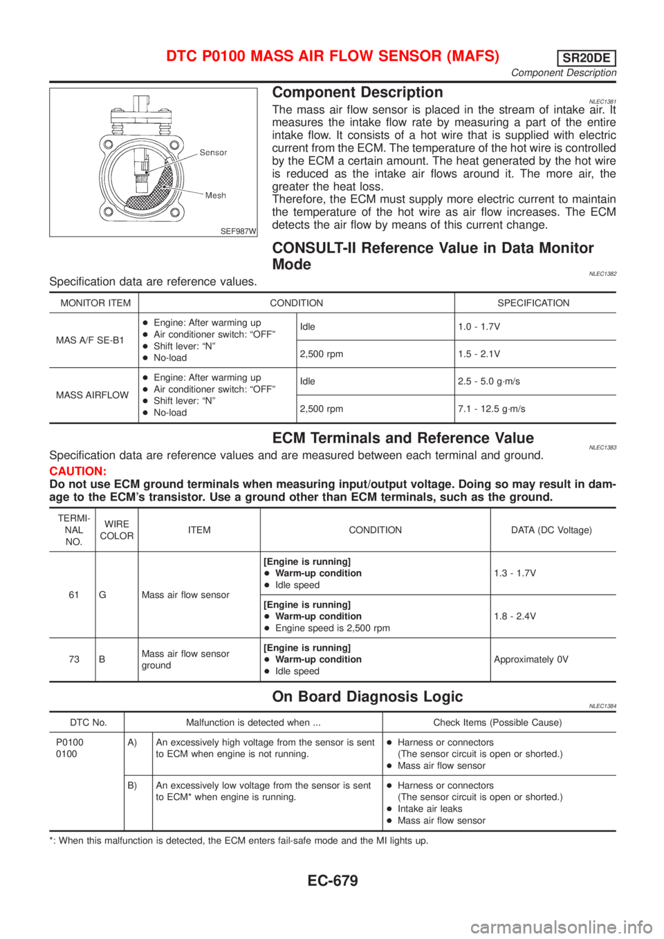
Component DescriptionNLEC1381The mass air flow sensor is placed in the stream of intake air. It
measures the intake flow rate by measuring a part of the entire
intake flow. It consists of a hot wire that is supplied with electric
current from the ECM. The temperature of the hot wire is controlled
by the ECM a certain amount. The heat generated by the hot wire
is reduced as the intake air flows around it. The more air, the
greater the heat loss.
Therefore, the ECM must supply more electric current to maintain
the temperature of the hot wire as air flow increases. The ECM
detects the air flow by means of this current change.
CONSULT-II Reference Value in Data Monitor
Mode
NLEC1382Specification data are reference values.
MONITOR ITEM CONDITION SPECIFICATION
MAS A/F SE-B1+Engine: After warming up
+Air conditioner switch: ªOFFº
+Shift lever: ªNº
+No-loadIdle 1.0 - 1.7V
2,500 rpm 1.5 - 2.1V
MASS AIRFLOW+Engine: After warming up
+Air conditioner switch: ªOFFº
+Shift lever: ªNº
+No-loadIdle 2.5 - 5.0 g´m/s
2,500 rpm 7.1 - 12.5 g´m/s
ECM Terminals and Reference ValueNLEC1383Specification data are reference values and are measured between each terminal and ground.
CAUTION:
Do not use ECM ground terminals when measuring input/output voltage. Doing so may result in dam-
age to the ECM's transistor. Use a ground other than ECM terminals, such as the ground.
TERMI-
NAL
NO.WIRE
COLORITEM CONDITION DATA (DC Voltage)
61 G Mass air flow sensor[Engine is running]
+Warm-up condition
+Idle speed1.3 - 1.7V
[Engine is running]
+Warm-up condition
+Engine speed is 2,500 rpm1.8 - 2.4V
73 BMass air flow sensor
ground[Engine is running]
+Warm-up condition
+Idle speedApproximately 0V
On Board Diagnosis LogicNLEC1384
DTC No. Malfunction is detected when ... Check Items (Possible Cause)
P0100
0100A) An excessively high voltage from the sensor is sent
to ECM when engine is not running.+Harness or connectors
(The sensor circuit is open or shorted.)
+Mass air flow sensor
B) An excessively low voltage from the sensor is sent
to ECM* when engine is running.+Harness or connectors
(The sensor circuit is open or shorted.)
+Intake air leaks
+Mass air flow sensor
*: When this malfunction is detected, the ECM enters fail-safe mode and the MI lights up.
DTC P0100 MASS AIR FLOW SENSOR (MAFS)SR20DE
Component Description
EC-679
Page 1119 of 3051

SEF594K
Component DescriptionNLEC1396The engine coolant temperature sensor is used to detect the
engine coolant temperature. The sensor modifies a voltage signal
from the ECM. The modified signal returns to the ECM as the
engine coolant temperature input. The sensor uses a thermistor
which is sensitive to the change in temperature. The electrical
resistance of the thermistor decreases as temperature increases.
SEF012P
Engine coolant temperature
ÉC (ÉF)Voltage*
VResistance
kW
þ10 (14) 4.4 7.0 - 11.4
20 (68) 3.5 2.1 - 2.9
50 (122) 2.2 0.68 - 1.00
90 (194) 0.9 0.236 - 0.260
*: These data are reference values and are measured between ECM terminal 70
(Engine coolant temperature sensor) and ground.
CAUTION:
Do not use ECM ground terminals when measuring input/
output voltage. Doing so may result in damage to the ECM's
transistor. Use a ground other than ECM terminals, such as
the ground.
CONSULT-II Reference Value in Data Monitor
Mode
NLEC1397
MONITOR ITEM CONDITION SPECIFICATION
COOLAN TEMP/S+Engine: After warming up More than 70ÉC (158ÉF)
On Board Diagnosis LogicNLEC1398
DTC No. Malfunction is detected when ... Check Items (Possible Cause)
P0115
0115+An excessively high or low voltage from the sensor is
sent to ECM.*+Harness or connectors
(The sensor circuit is open or shorted.)
+Engine coolant temperature sensor
*: When this malfunction is detected, the ECM enters fail-safe mode and the MI lights up.
DTC P0115 ENGINE COOLANT TEMPERATURE SENSOR (ECTS)
(CIRCUIT)
SR20DE
Component Description
EC-694
Page 1126 of 3051

ECM Terminals and Reference Value=NLEC1406Specification data are reference values and are measured between each terminal and ground.
CAUTION:
Do not use ECM ground terminals when measuring input/output voltage. Doing so may result in dam-
age to the ECM's transistor. Use a ground other than ECM terminals, such as the ground.
TERMI-
NAL
NO.WIRE
COLORITEM CONDITION DATA (DC Voltage)
58 B Sensors' ground[Engine is running]
+Warm up condition
+Idle speedApproximately 0V
92 Y Throttle position sensor[Engine is running]
+Accelerator pedal fully released0.15 - 0.85V
[Ignition switch ªONº]
+Accelerator pedal fully depressed3.5 - 4.7V
111 R Sensors' power supply[Ignition switch ªONº]Approximately 5V
On Board Diagnosis LogicNLEC1407
DTC No. Malfunction is detected when ... Check Items (Possible Cause)
P0120
0120An excessively low or high voltage from the sensor is
sent to ECM* while driving.+Harness or connectors
(The throttle position sensor circuit is open or
shorted.)
+Throttle position sensor
*: When this malfunction is detected, the ECM enters fail-safe mode and the MI lights up.
Fail-safe ModeNLEC1408
Detected items Engine operating condition in fail-safe mode
Throttle position sensor
circuitThrottle position will be determined based on the injected fuel amount and the engine speed.
Therefore, acceleration will be poor.
Condition Driving condition
When engine is idling Normal
When accelerating Poor acceleration
DTC Confirmation ProcedureNLEC1409NOTE:
If ªDTC Confirmation Procedureº has been previously conducted,
always turn ignition switch ªOFFº and wait at least 10 seconds
before conducting the next test.
CAUTION:
Always drive vehicle at a safe speed.
TESTING CONDITION:
+Before performing the following procedure, confirm that
battery voltage is more than 10V at idle.
+This test may be conducted with the drive wheels lifted in
DTC P0120 THROTTLE POSITION SENSORSR20DE
ECM Terminals and Reference Value
EC-701
Page 1217 of 3051
On Board Diagnosis LogicNLEC1507With the Air/Fuel Mixture Ratio Self-Learning Control, the actual mixture ratio can be brought closely to the
theoretical mixture ratio based on the mixture ratio feedback signal from the heated oxygen sensor 1 (front).
The ECM calculates the necessary compensation to correct the offset between the actual and the theoretical
ratios.
In case the amount of the compensation value is extremely large (The actual mixture ratio is too lean.), the
ECM judges the condition as the fuel injection system malfunction and lights up the MIL (2 trip detection logic).
Sensor Input Signal to ECM ECM function Actuator
Heated oxygen sensor 1 (front)Density of oxygen in exhaust gas
(Mixture ratio feedback signal)Fuel injection & mixture
ratio controlInjectors
DTC No. Malfunction is detected when ... Check Items (Possible Cause)
P0171+Fuel injection system does not operate properly.
+The amount of mixture ratio compensation is too large.
(The mixture ratio is too lean.)+Intake air leaks
+Heated oxygen sensor 1 (front)
+Injectors
+Exhaust gas leaks
+Incorrect fuel pressure
+Lack of fuel
+Mass air flow sensor
SEF215Z
SEF058Y
DTC Confirmation ProcedureNLEC1508NOTE:
If ªDTC Confirmation Procedureº has been previously conducted,
always turn ignition switch ªOFFº and wait at least 10 seconds
before conducting the next test.
With CONSULT-II
1) Start engine and warm it up to normal operating temperature.
2) Turn ignition switch ªOFFº and wait at least 10 seconds.
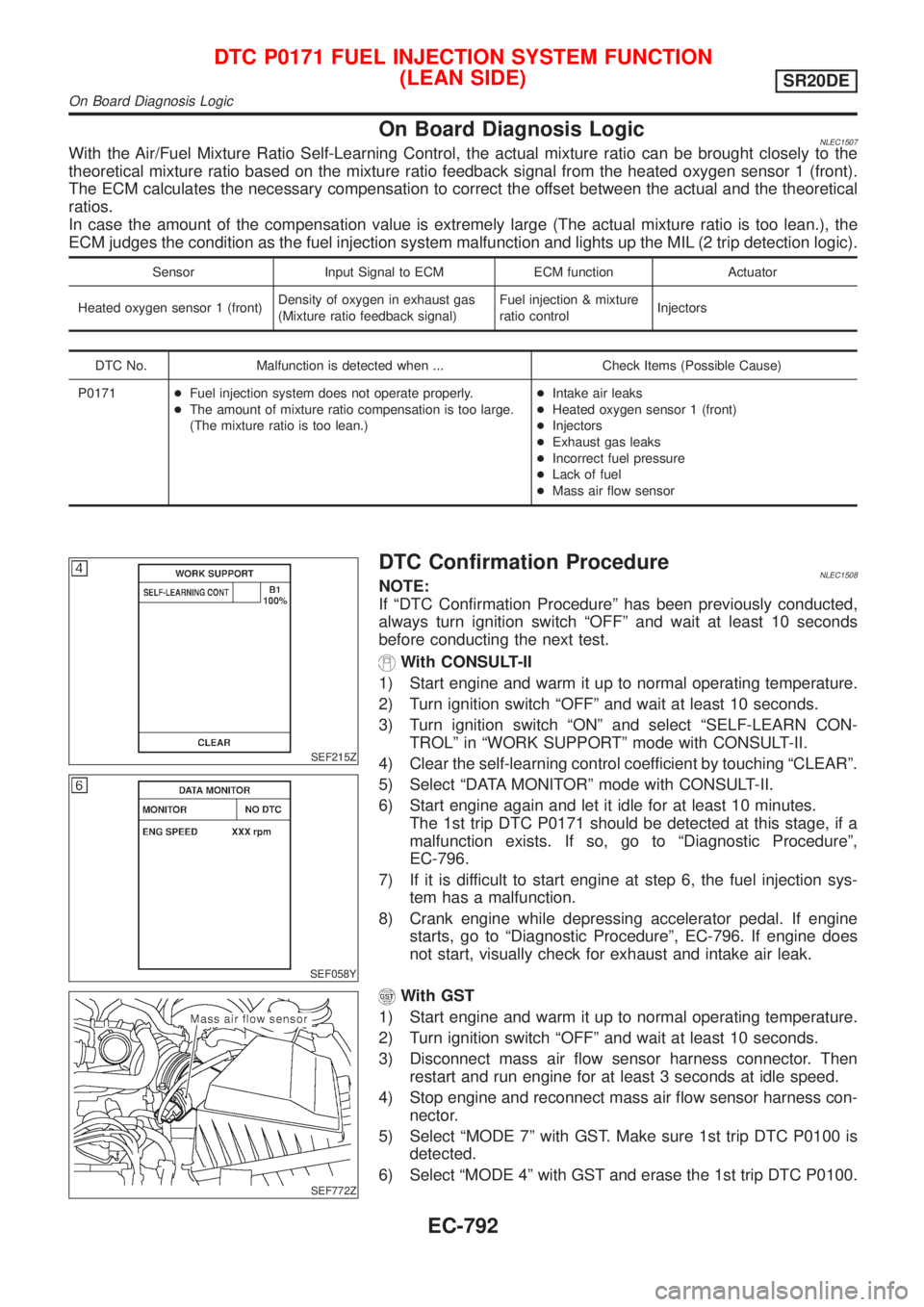
3) Turn ignition switch ªONº and select ªSELF-LEARN CON-
TROLº in ªWORK SUPPORTº mode with CONSULT-II.
4) Clear the self-learning control coefficient by touching ªCLEARº.
5) Select ªDATA MONITORº mode with CONSULT-II.
6) Start engine again and let it idle for at least 10 minutes.
The 1st trip DTC P0171 should be detected at this stage, if a
malfunction exists. If so, go to ªDiagnostic Procedureº,
EC-796.
7) If it is difficult to start engine at step 6, the fuel injection sys-
tem has a malfunction.
8) Crank engine while depressing accelerator pedal. If engine
starts, go to ªDiagnostic Procedureº, EC-796. If engine does
not start, visually check for exhaust and intake air leak.
SEF772Z
With GST
1) Start engine and warm it up to normal operating temperature.
2) Turn ignition switch ªOFFº and wait at least 10 seconds.
3) Disconnect mass air flow sensor harness connector. Then
restart and run engine for at least 3 seconds at idle speed.
4) Stop engine and reconnect mass air flow sensor harness con-
nector.
5) Select ªMODE 7º with GST. Make sure 1st trip DTC P0100 is
detected.
6) Select ªMODE 4º with GST and erase the 1st trip DTC P0100.
DTC P0171 FUEL INJECTION SYSTEM FUNCTION
(LEAN SIDE)
SR20DE
On Board Diagnosis Logic
EC-792
Page 1225 of 3051
On Board Diagnosis LogicNLEC1511With the Air/Fuel Mixture Ratio Self-Learning Control, the actual mixture ratio can be brought closely to the
theoretical mixture ratio based on the mixture ratio feedback signal from the heated oxygen sensor 1 (front).
The ECM calculates the necessary compensation to correct the offset between the actual and the theoretical
ratios.
In case the amount of the compensation value is extremely large (The actual mixture ratio is too rich.), the
ECM judges the condition as the fuel injection system malfunction and lights up the MI (2 trip detection logic).
Sensor Input Signal to ECM ECM function Actuator
Heated oxygen sensor 1 (front)Density of oxygen in exhaust gas
(Mixture ratio feedback signal)Fuel injection & mixture
ratio controlInjectors
DTC No. Malfunction is detected when ... Check Items (Possible Cause)
P0172+Fuel injection system does not operate properly.
+The amount of mixture ratio compensation is too large.
(The mixture ratio is too rich.)+Heated oxygen sensor 1 (front)
+Injectors
+Exhaust gas leaks
+Incorrect fuel pressure
+Mass air flow sensor
SEF215Z
SEF058Y
DTC Confirmation ProcedureNLEC1512NOTE:
If ªDTC Confirmation Procedureº has been previously conducted,
always turn ignition switch ªOFFº and wait at least 10 seconds
before conducting the next test.
With CONSULT-II
1) Start engine and warm it up to normal operating temperature.
2) Turn ignition switch ªOFFº and wait at least 10 seconds.
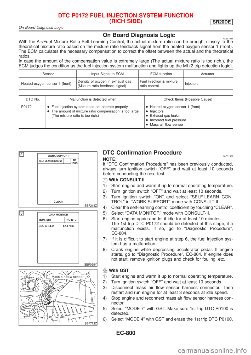
3) Turn ignition switch ªONº and select ªSELF-LEARN CON-
TROLº in ªWORK SUPPORTº mode with CONSULT-II.
4) Clear the self-learning control coefficient by touching ªCLEARº.
5) Select ªDATA MONITORº mode with CONSULT-II.
6) Start engine again and let it idle for at least 10 minutes.
The 1st trip DTC P0172 should be detected at this stage, if a
malfunction exists. If so, go to ªDiagnostic Procedureº,
EC-804.
7) If it is difficult to start engine at step 6, the fuel injection sys-
tem has a malfunction.
8) Crank engine while depressing accelerator pedal. If engine
starts, go to ªDiagnostic Procedureº, EC-804. If engine does
not start, remove ignition plugs and check for fouling, etc.
SEF772Z
With GST
1) Start engine and warm it up to normal operating temperature.
2) Turn ignition switch ªOFFº and wait at least 10 seconds.
3) Disconnect mass air flow sensor harness connector. Then
restart and run engine for at least 3 seconds at idle speed.
4) Stop engine and reconnect mass air flow sensor harness con-
nector.
5) Select ªMODE 7º with GST. Make sure 1st trip DTC P0100 is
detected.
6) Select ªMODE 4º with GST and erase the 1st trip DTC P0100.
DTC P0172 FUEL INJECTION SYSTEM FUNCTION
(RICH SIDE)
SR20DE
On Board Diagnosis Logic
EC-800
Page 1233 of 3051
On Board Diagnosis LogicNLEC1752When a misfire occurs, engine speed will fluctuate (vary). If the engine speed fluctuates enough to cause the
CKP sensor to vary, ECM can detect a misfire.
Sensor Input Signal to ECM ECM function
Crankshaft position sensor (OBD) Engine speed On board diagnosis of misfire
The misfire detection logic consists of the following two conditions.
1. One Trip Detection Logic (Three Way Catalyst Damage)
On the first rip that a misfire condition occurs that can damage the three way catalyst (TWC) due to
overheating, the MI will blink.
When a misfire condition occurs, the ECM monitors the CKP sensor (OBD) signal every 200 engine revo-
lutions for a change.
When the misfire condition decreases to a level that will not damage the TWC, the MI will turn off.
If another misfire condition occurs that can damage the TWC on a second trip, the MI will blink.
When the misfire condition decreases to a level that will not damage the TWC, the MI will remain on.
If another misfire condition occurs that can damage the TWC, the MI will begin to blink again.
2. Two Trip Detection Logic (Exhaust quality deterioration)
For misfire conditions that will not cause damage to the TWC (but will affect vehicle emissions), the MI
will only light when the misfire is detected on a second trip. During this condition, the ECM monitors the
CKP sensor (OBD) signal every 1,000 engine revolutions.
A misfire malfunction can be detected on any one cylinder or on-multiple cylinders.
DTC No. Malfunction is detected when ... Check Items (Possible Cause)
P0300+Multiple cylinders misfire.+Improper spark plug
+Insufficient compression
+Incorrect fuel pressure
+EGR volume control valve
+The injector circuit is open or shorted
+Injectors
+Intake air leak
+The ignition secondary circuit is open or shorted
+Lack of fuel
+Drive plate
+Heated oxygen sensor 1 (front)
+Incorrect distributor roter P0301+No. 1 cylinder misfires.
P0302+No. 2 cylinder misfires.
P0303+No. 3 cylinder misfires.
P0304+No. 4 cylinder misfires.
SEF058Y
DTC Confirmation ProcedureNLEC1522CAUTION:
Always drive vehicle at a safe speed.
NOTE:
If ªDTC Confirmation Procedureº has been previously conducted,
always turn ignition switch ªOFFº and wait at least 10 seconds
before conducting the next test.
With CONSULT-II
1) Turn ignition switch ªONº, and select ªDATA MONITORº mode
with CONSULT-II.
2) Start engine and warm it up to normal operating temperature.
3) Turn ignition switch ªOFFº and wait at least 10 seconds.
4) Start engine again and drive at 1,500 - 3,000 rpm for at least
3 minutes.
Hold the accelerator pedal as steady as possible.
NOTE:
Refer to the freeze frame data for the test driving conditions.
5) If 1st trip DTC is detected, go to ªDiagnostic Procedureº,
EC-809.
With GST
Follow the procedure ªWith CONSULT-IIº above.
DTC P0300 - P0304 NO.4-1CYLINDER MISFIRE, MULTIPLE CYLINDER
MISFIRE
SR20DE
On Board Diagnosis Logic
EC-808
Page 1240 of 3051
SEF598K
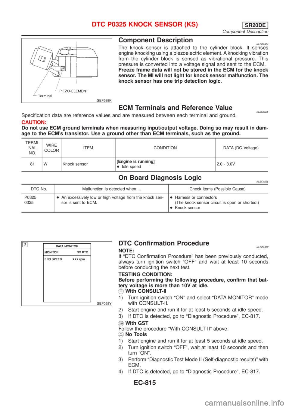
Component DescriptionNLEC1524The knock sensor is attached to the cylinder block. It senses
engine knocking using a piezoelectric element. A knocking vibration
from the cylinder block is sensed as vibrational pressure. This
pressure is converted into a voltage signal and sent to the ECM.
Freeze frame data will not be stored in the ECM for the knock
sensor. The MI will not light for knock sensor malfunction. The
knock sensor has one trip detection logic.
ECM Terminals and Reference ValueNLEC1525Specification data are reference values and are measured between each terminal and ground.
CAUTION:
Do not use ECM ground terminals when measuring input/output voltage. Doing so may result in dam-
age to the ECM's transistor. Use a ground other than ECM terminals, such as the ground.
TERMI-
NAL
NO.WIRE
COLORITEM CONDITION DATA (DC Voltage)
81 W Knock sensor[Engine is running]
+Idle speed2.0 - 3.0V
On Board Diagnosis LogicNLEC1526
DTC No. Malfunction is detected when ... Check Items (Possible Cause)
P0325
0325+An excessively low or high voltage from the knock sen-
sor is sent to ECM.+Harness or connectors
(The knock sensor circuit is open or shorted.)
+Knock sensor
SEF058Y
DTC Confirmation ProcedureNLEC1527NOTE:
If ªDTC Confirmation Procedureº has been previously conducted,
always turn ignition switch ªOFFº and wait at least 10 seconds
before conducting the next test.
TESTING CONDITION:
Before performing the following procedure, confirm that bat-
tery voltage is more than 10V at idle.
With CONSULT-II
1) Turn ignition switch ªONº and select ªDATA MONITORº mode
with CONSULT-II.
2) Start engine and run it for at least 5 seconds at idle speed.
3) If DTC is detected, go to ªDiagnostic Procedureº, EC-817.
With GST
Follow the procedure ªWith CONSULT-IIº above.
No Tools
1) Start engine and run it for at least 5 seconds at idle speed.
2) Turn ignition switch ªOFFº, wait at least 10 seconds and then
turn ªONº.
3) Perform ªDiagnostic Test Mode II (Self-diagnostic results)º with
ECM.
4) If DTC is detected, go to ªDiagnostic Procedureº, EC-817.
DTC P0325 KNOCK SENSOR (KS)SR20DE
Component Description
EC-815
Page 1293 of 3051

4 CHECK AIR CONTROL VALVE (POWER STEERING) OPERATION-I
1. Reconnect the ECM harness connector and IACV-AAC valve harness connector.
2. Disconnect the vacuum hose connected to the air control valve (Power steering) at intake air duct.
3. Start engine and let it idle.
4. Check vacuum hose for vacuum existence.
SEF778Z
Vacuum does not exist or slightly exist.
OK or NG
OK©GO TO 5.
NG©Replace air control valve (Power steering).
5 CHECK AIR CONTROL VALVE (POWER STEERING) OPERATION-II
Check the vacuum hose for vacuum existence when steering wheel is turned.
SEF778Z
Vacuum should exist.
OK or NG
OK©GO TO 8.
NG©GO TO 6.
DTC P0505 IDLE AIR CONTROL VALVE (IACV) Ð AUXILIARY AIR CONTROL
(AAC) VALVE
SR20DE
Diagnostic Procedure (Cont'd)
EC-868
Page 1297 of 3051

SEF505V
Component DescriptionNLEC1587A closed throttle position switch and wide open throttle position
switch are built into the throttle position sensor unit. The wide open
throttle position switch is used only for A/T control.
When the throttle valve is in the closed position, the closed throttle
position switch sends a voltage signal to the ECM. The ECM only
uses this signal to open or close the EVAP canister purge control
valve when the throttle position sensor is malfunctioning.
CONSULT-II Reference Value in Data Monitor
Mode
NLEC1588Specification data are reference values.
MONITOR ITEM CONDITION SPECIFICATION
CLSD THL/P SW+Engine: IdleThrottle valve: Idle position ON
Throttle valve: Slightly open OFF
ECM Terminals and Reference ValueNLEC1589Specification data are reference values and are measured between each terminal and ground.
CAUTION:
Do not use ECM ground terminals when measuring input/output voltage. Doing so may result in dam-
age to the ECM's transistor. Use a ground other than ECM terminals, such as the ground.
TER-
MINAL
NO.WIRE
COLORITEM CONDITION DATA (DC Voltage)
40 Y/PUThrottle position switch
(Closed position)[Engine is running]
+Accelerator pedal releasedBATTERY VOLTAGE
(11 - 14V)
[Ignition switch ªONº]
+Accelerator pedal depressedApproximately 0V
On Board Diagnosis LogicNLEC1590
DTC No. Malfunction is detected when ... Check Items (Possible Cause)
P0510
0510+Battery voltage from the closed throttle position switch is
sent to ECM with the throttle valve opened.+Harness or connectors
(The closed throttle position switch circuit is
shorted.)
+Closed throttle position switch
+Throttle position sensor
SEF197Y
DTC Confirmation ProcedureNLEC1591CAUTION:
Always drive vehicle at a safe speed.
NOTE:
If ªDTC Confirmation Procedureº has been previously conducted,
always turn ignition switch ªOFFº and wait at least 10 seconds
before conducting the next test.
With CONSULT-II
1) Start engine and warm it up to normal operating temperature.
2) Turn ignition switch ªOFFº, wait at least 10 seconds and then
start engine.
DTC P0510 CLOSED THROTTLE POSITION SWITCHSR20DE
Component Description
EC-872