lock NISSAN ALMERA TINO 2001 Service Repair Manual
[x] Cancel search | Manufacturer: NISSAN, Model Year: 2001, Model line: ALMERA TINO, Model: NISSAN ALMERA TINO 2001Pages: 3051, PDF Size: 46.38 MB
Page 4 of 3051
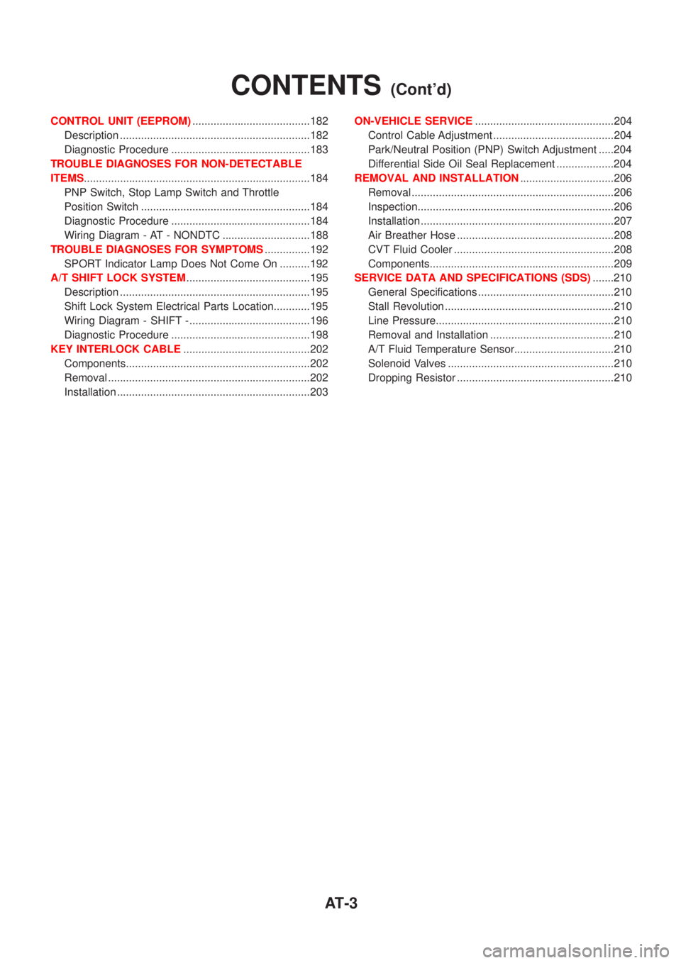
CONTROL UNIT (EEPROM).......................................182
Description ...............................................................182
Diagnostic Procedure ..............................................183
TROUBLE DIAGNOSES FOR NON-DETECTABLE
ITEMS...........................................................................184
PNP Switch, Stop Lamp Switch and Throttle
Position Switch ........................................................184
Diagnostic Procedure ..............................................184
Wiring Diagram - AT - NONDTC .............................188
TROUBLE DIAGNOSES FOR SYMPTOMS...............192
SPORT Indicator Lamp Does Not Come On ..........192
A/T SHIFT LOCK SYSTEM.........................................195
Description ...............................................................195
Shift Lock System Electrical Parts Location............195
Wiring Diagram - SHIFT -........................................196
Diagnostic Procedure ..............................................198
KEY INTERLOCK CABLE..........................................202
Components.............................................................202
Removal ...................................................................202
Installation ................................................................203ON-VEHICLE SERVICE..............................................204
Control Cable Adjustment ........................................204
Park/Neutral Position (PNP) Switch Adjustment .....204
Differential Side Oil Seal Replacement ...................204
REMOVAL AND INSTALLATION...............................206
Removal ...................................................................206
Inspection.................................................................206
Installation ................................................................207
Air Breather Hose ....................................................208
CVT Fluid Cooler .....................................................208
Components.............................................................209
SERVICE DATA AND SPECIFICATIONS (SDS).......210
General Specifications .............................................210
Stall Revolution ........................................................210
Line Pressure...........................................................210
Removal and Installation .........................................210
A/T Fluid Temperature Sensor.................................210
Solenoid Valves .......................................................210
Dropping Resistor ....................................................210
CONTENTS(Cont'd)
AT-3
Page 7 of 3051
Precautions for Supplemental Restraint System
(SRS) ªAIR BAGº and ªSEAT BELT
PRE-TENSIONERº
NLAT0002The Supplemental Restraint System ªAIR BAGº and ªSEAT BELT PRE-TENSIONERº, used along with a seat
belt, help to reduce the risk or severity of injury to the driver and front passenger in a frontal collision. The
Supplemental Restraint System consists of air bag modules (located in the center of the steering wheel and
on the instrument panel on the passenger side), seat belt pre-tensioners, a diagnosis sensor unit, warning
lamp, wiring harness and spiral cable.
In addition to the supplemental air bag modules for a frontal collision, the supplemental side air bag used along
with the seat belt helps to reduce the risk or severity of injury to the driver and front passenger in a side col-
lision. The supplemental side air bag consists of air bag modules (located in the outer side of front seats),
satellite sensor, diagnosis sensor unit (one of components of supplemental air bags for a frontal collision),
wiring harness, warning lamp (one of components of supplemental air bags for a frontal collision). Information
necessary to service the system safely is included in theRS sectionof this Service Manual.
WARNING:
+To avoid rendering the SRS inoperative, which could increase the risk of personal injury or death
in the event of a collision which would result in air bag inflation, all maintenance must be performed
by an authorized NISSAN dealer.
+Improper maintenance, including incorrect removal and installation of the SRS, can lead to per-
sonal injury caused by unintentional activation of the system.
+Do not use electrical test equipment on any circuit related to the SRS unless instructed to in this
Service Manual. SRS wiring harnesses can be identified with yellow harness connector (and with
yellow harness protector or yellow insulation tape before the harness connectors).
Precautions for On Board Diagnostic (EURO-
OBD) System of CVT and Engine
NLAT0198The ECM has an on board diagnostic system. It will light up the malfunction indicator lamp (MI) to warn the
driver of a malfunction causing emission deterioration.
CAUTION:
+Be sure to turn the ignition switch ªOFFº and disconnect the negative battery terminal before any
repair or inspection work. The open/short circuit of related switches, sensors, solenoid valves, etc.
will cause the MI to light up.
+Be sure to connect and lock the connectors securely after work. A loose (unlocked) connector will
cause the MI to light up due to an open circuit. (Be sure the connector is free from water, grease,
dirt, bent terminals, etc.)
+Be sure to route and secure the harnesses properly after work. Interference of the harness with a
bracket, etc. may cause the MI to light up due to a short circuit.
+Be sure to connect rubber tubes properly after work. A misconnected or disconnected rubber tube
may cause the MI to light up due to a malfunction of the EGR system or fuel injection system, etc.
+Be sure to erase the unnecessary malfunction information (repairs completed) from the TCM and
ECM before returning the vehicle to the customer.
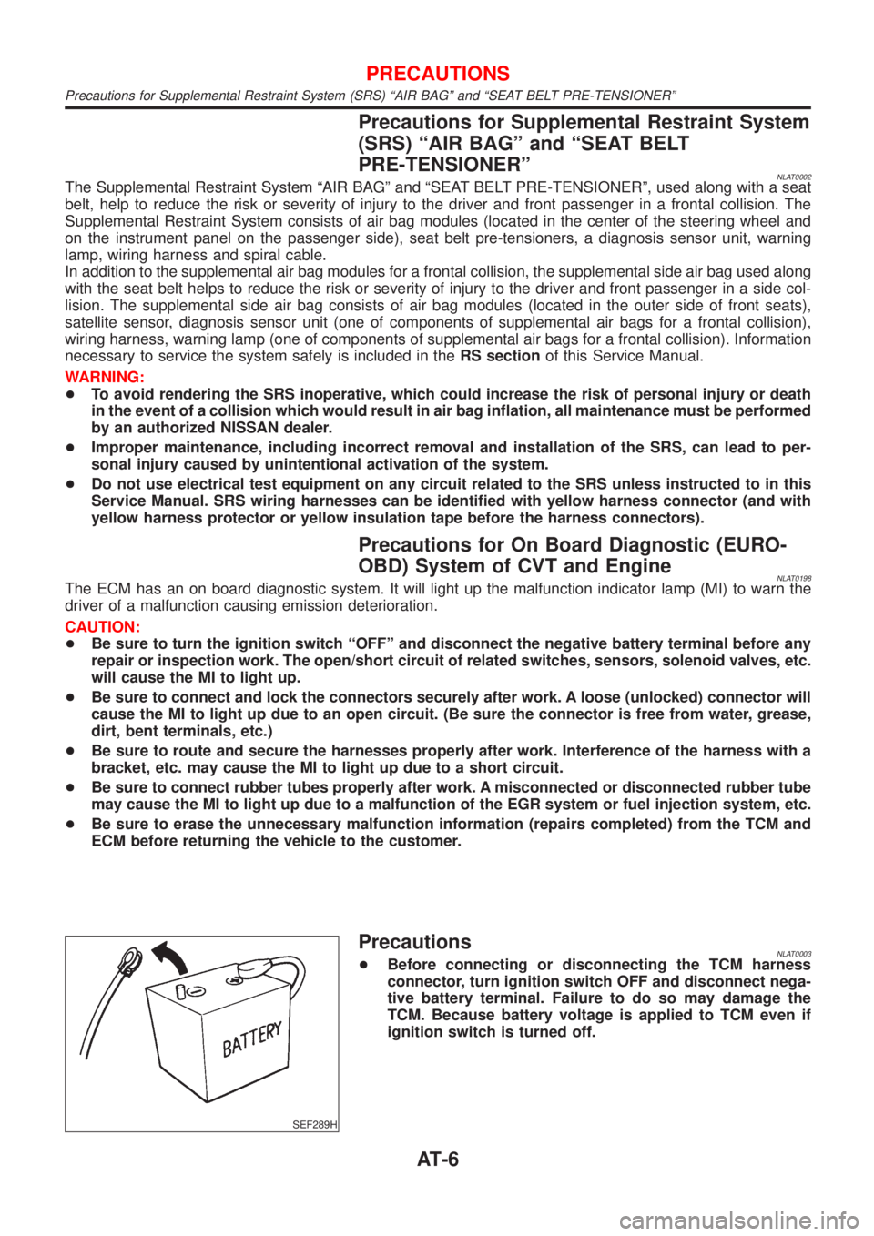
SEF289H
PrecautionsNLAT0003+Before connecting or disconnecting the TCM harness
connector, turn ignition switch OFF and disconnect nega-
tive battery terminal. Failure to do so may damage the
TCM. Because battery voltage is applied to TCM even if
ignition switch is turned off.
PRECAUTIONS
Precautions for Supplemental Restraint System (SRS) ªAIR BAGº and ªSEAT BELT PRE-TENSIONERº
AT-6
Page 9 of 3051
The SELF-DIAGNOSIS results will be as follows:
The first SELF-DIAGNOSIS will indicate damage to the vehicle speed sensor or the revolution sensor.
During the next SELF-DIAGNOSIS, performed after checking the sensor, no damages will be indicated.
EURO-OBD SELF-DIAGNOSISNLAT0004S04+CVT self-diagnosis is performed by the TCM in combination with the ECM. The results can be read through
the blinking pattern of the SPORT indicator lamp. Refer to the table on AT-22 for the indicator used to dis-
play each self-diagnostic result.
+The self-diagnostic results indicated by the MI are automatically stored in both the ECM and TCM memo-
ries.
Always perform the procedure ªHOW TO ERASE DTCº on AT-19 to complete the repair and avoid
unnecessary blinking of the MI.
For details of EURO-OBD, refer to EC section (ªON BOARD DIAGNOSTIC SYSTEM DESCRIPTIONº).
+Certain systems and components, especially those related to EURO-OBD, may use a new style
slide-locking type harness connector.
For description and how to disconnect, refer to EL section, ªDescriptionº, ªHARNESS CONNEC-
TORº.
Wiring Diagrams and Trouble DiagnosesNLAT0005When you read wiring diagrams, refer to the following:
+ªHOW TO READ WIRING DIAGRAMSº in GI section
+ªPOWER SUPPLY ROUTINGº for power distribution circuit in EL section
When you perform trouble diagnoses, refer to the following:
+ªHOW TO FOLLOW TEST GROUPS IN TROUBLE DIAGNOSESº in GI section
+ªHOW TO PERFORM EFFICIENT DIAGNOSIS FOR AN ELECTRICAL INCIDENTº in GI section
PRECAUTIONS
Service Notice or Precautions (Cont'd)
AT-8
Page 16 of 3051
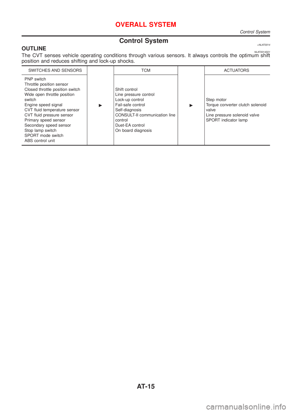
Control System=NLAT0014OUTLINENLAT0014S01The CVT senses vehicle operating conditions through various sensors. It always controls the optimum shift
position and reduces shifting and lock-up shocks.
SWITCHES AND SENSORS
cTCM
cACTUATORS
PNP switch
Throttle position sensor
Closed throttle position switch
Wide open throttle position
switch
Engine speed signal
CVT fluid temperature sensor
CVT fluid pressure sensor
Primary speed sensor
Secondary speed sensor
Stop lamp switch
SPORT mode switch
ABS control unitShift control
Line pressure control
Lock-up control
Fail-safe control
Self-diagnosis
CONSULT-II communication line
control
Duet-EA control
On board diagnosisStep motor
Torque converter clutch solenoid
valve
Line pressure solenoid valve
SPORT indicator lamp
OVERALL SYSTEM
Control System
AT-15
Page 18 of 3051
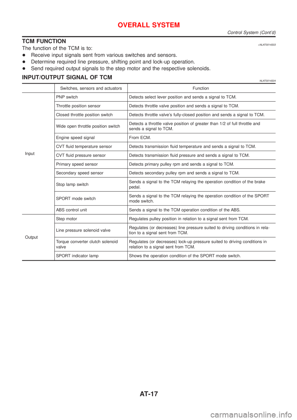
TCM FUNCTION=NLAT0014S03The function of the TCM is to:
+Receive input signals sent from various switches and sensors.
+Determine required line pressure, shifting point and lock-up operation.
+Send required output signals to the step motor and the respective solenoids.
INPUT/OUTPUT SIGNAL OF TCMNLAT0014S04
Switches, sensors and actuators Function
InputPNP switch Detects select lever position and sends a signal to TCM.
Throttle position sensor Detects throttle valve position and sends a signal to TCM.
Closed throttle position switch Detects throttle valve's fully-closed position and sends a signal to TCM.
Wide open throttle position switchDetects a throttle valve position of greater than 1/2 of full throttle and
sends a signal to TCM.
Engine speed signal From ECM.
CVT fluid temperature sensor Detects transmission fluid temperature and sends a signal to TCM.
CVT fluid pressure sensor Detects transmission fluid pressure and sends a signal to TCM.
Primary speed sensor Detects primary pulley rpm and sends a signal to TCM.
Secondary speed sensor Detects secondary pulley rpm and sends a signal to TCM.
Stop lamp switchSends a signal to the TCM relaying the operation condition of the brake
pedal.
SPORT mode switchSends a signal to the TCM relaying the operation condition of the SPORT
mode switch.
ABS control unit Sends a signal to the TCM operation condition of the ABS.
OutputStep motor Regulates pulley position in relation to a signal sent from TCM.
Line pressure solenoid valveRegulates (or decreases) line pressure suited to driving conditions in rela-
tion to a signal sent from TCM.
Torque converter clutch solenoid
valveRegulates (or decreases) lock-up pressure suited to driving conditions in
relation to a signal sent from TCM.
SPORT indicator lamp Shows the operation condition of the SPORT mode switch.
OVERALL SYSTEM
Control System (Cont'd)
AT-17
Page 30 of 3051
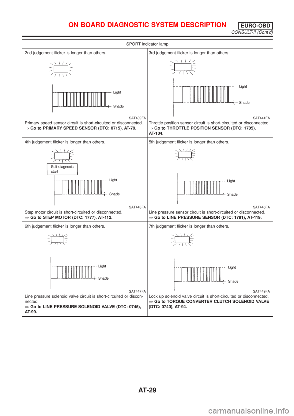
SPORT indicator lamp
2nd judgement flicker is longer than others.
SAT439FA
Primary speed sensor circuit is short-circuited or disconnected.
ÞGo to PRIMARY SPEED SENSOR (DTC: 0715), AT-79.3rd judgement flicker is longer than others.
SAT441FA
Throttle position sensor circuit is short-circuited or disconnected.
ÞGo to THROTTLE POSITION SENSOR (DTC: 1705),
AT-104.
4th judgement flicker is longer than others.
SAT443FA
Step motor circuit is short-circuited or disconnected.
ÞGo to STEP MOTOR (DTC: 1777), AT-112.5th judgement flicker is longer than others.
SAT445FA
Line pressure sensor circuit is short-circuited or disconnected.
ÞGo to LINE PRESSURE SENSOR (DTC: 1791), AT-119.
6th judgement flicker is longer than others.
SAT447FA
Line pressure solenoid valve circuit is short-circuited or discon-
nected.
ÞGo to LINE PRESSURE SOLENOID VALVE (DTC: 0745),
AT-99.7th judgement flicker is longer than others.
SAT449FA
Lock up solenoid valve circuit is short-circuited or disconnected.
ÞGo to TORQUE CONVERTER CLUTCH SOLENOID VALVE
(DTC: 0740), AT-94.
ON BOARD DIAGNOSTIC SYSTEM DESCRIPTIONEURO-OBD
CONSULT-II (Cont'd)
AT-29
Page 40 of 3051
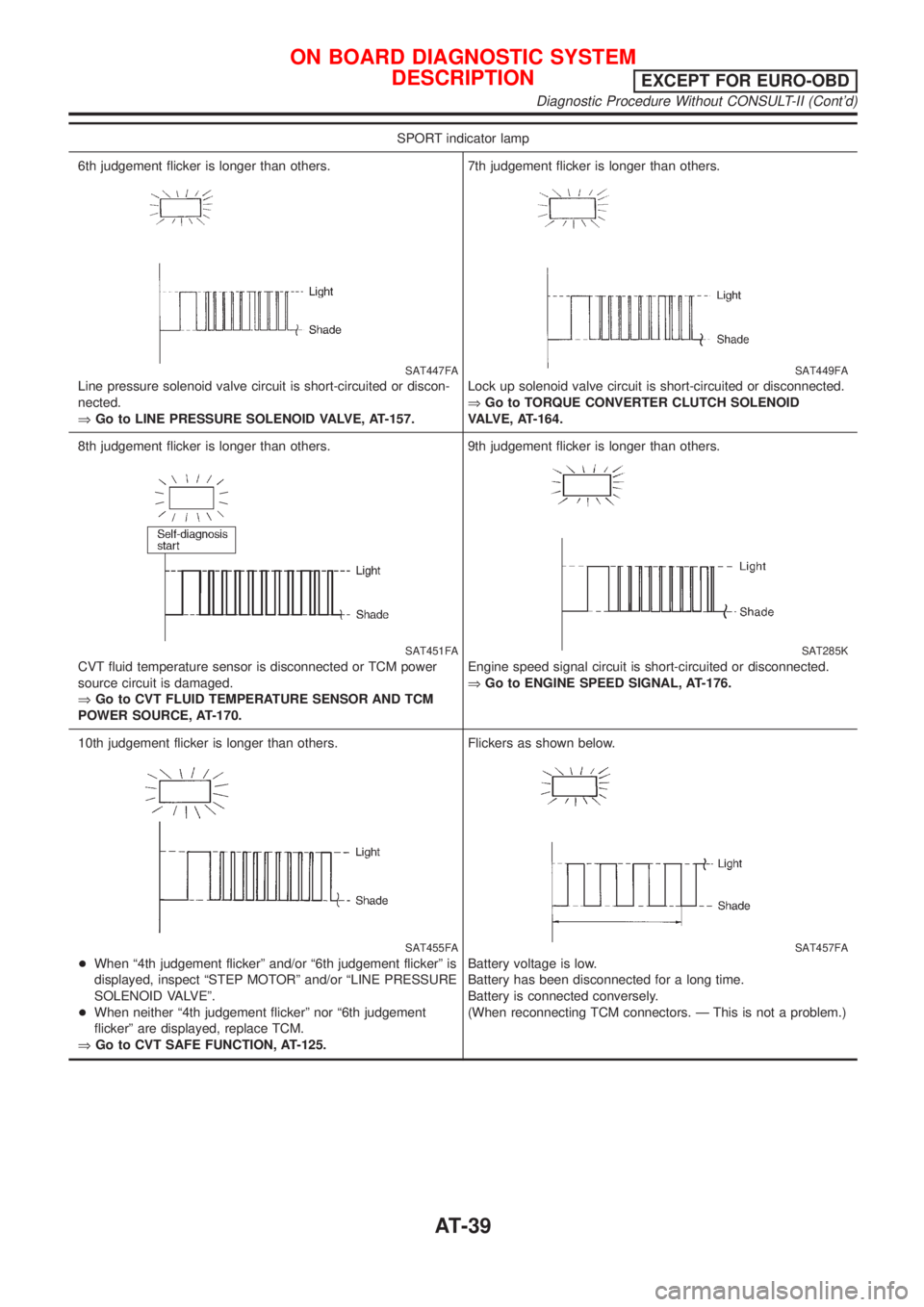
SPORT indicator lamp
6th judgement flicker is longer than others.
SAT447FA
Line pressure solenoid valve circuit is short-circuited or discon-
nected.
ÞGo to LINE PRESSURE SOLENOID VALVE, AT-157.7th judgement flicker is longer than others.
SAT449FA
Lock up solenoid valve circuit is short-circuited or disconnected.
ÞGo to TORQUE CONVERTER CLUTCH SOLENOID
VALVE, AT-164.
8th judgement flicker is longer than others.
SAT451FA
CVT fluid temperature sensor is disconnected or TCM power
source circuit is damaged.
ÞGo to CVT FLUID TEMPERATURE SENSOR AND TCM
POWER SOURCE, AT-170.9th judgement flicker is longer than others.
SAT285K
Engine speed signal circuit is short-circuited or disconnected.
ÞGo to ENGINE SPEED SIGNAL, AT-176.
10th judgement flicker is longer than others.
SAT455FA
+When ª4th judgement flickerº and/or ª6th judgement flickerº is
displayed, inspect ªSTEP MOTORº and/or ªLINE PRESSURE
SOLENOID VALVEº.
+When neither ª4th judgement flickerº nor ª6th judgement
flickerº are displayed, replace TCM.
ÞGo to CVT SAFE FUNCTION, AT-125.Flickers as shown below.
SAT457FA
Battery voltage is low.
Battery has been disconnected for a long time.
Battery is connected conversely.
(When reconnecting TCM connectors. Ð This is not a problem.)
ON BOARD DIAGNOSTIC SYSTEM
DESCRIPTION
EXCEPT FOR EURO-OBD
Diagnostic Procedure Without CONSULT-II (Cont'd)
AT-39
Page 42 of 3051
SAT631IA
SAT632I
SEF234G
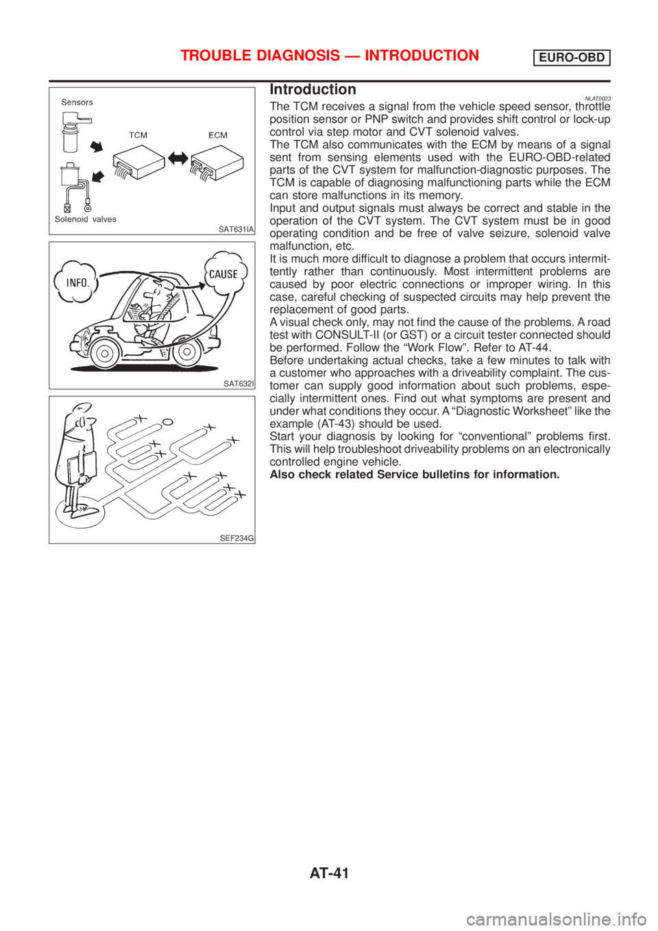
IntroductionNLAT0023The TCM receives a signal from the vehicle speed sensor, throttle
position sensor or PNP switch and provides shift control or lock-up
control via step motor and CVT solenoid valves.
The TCM also communicates with the ECM by means of a signal
sent from sensing elements used with the EURO-OBD-related
parts of the CVT system for malfunction-diagnostic purposes. The
TCM is capable of diagnosing malfunctioning parts while the ECM
can store malfunctions in its memory.
Input and output signals must always be correct and stable in the
operation of the CVT system. The CVT system must be in good
operating condition and be free of valve seizure, solenoid valve
malfunction, etc.
It is much more difficult to diagnose a problem that occurs intermit-
tently rather than continuously. Most intermittent problems are
caused by poor electric connections or improper wiring. In this
case, careful checking of suspected circuits may help prevent the
replacement of good parts.
A visual check only, may not find the cause of the problems. A road
test with CONSULT-II (or GST) or a circuit tester connected should
be performed. Follow the ªWork Flowº. Refer to AT-44.
Before undertaking actual checks, take a few minutes to talk with
a customer who approaches with a driveability complaint. The cus-
tomer can supply good information about such problems, espe-
cially intermittent ones. Find out what symptoms are present and
under what conditions they occur. A ªDiagnostic Worksheetº like the
example (AT-43) should be used.
Start your diagnosis by looking for ªconventionalº problems first.
This will help troubleshoot driveability problems on an electronically
controlled engine vehicle.
Also check related Service bulletins for information.
TROUBLE DIAGNOSIS Ð INTRODUCTIONEURO-OBD
AT-41
Page 43 of 3051
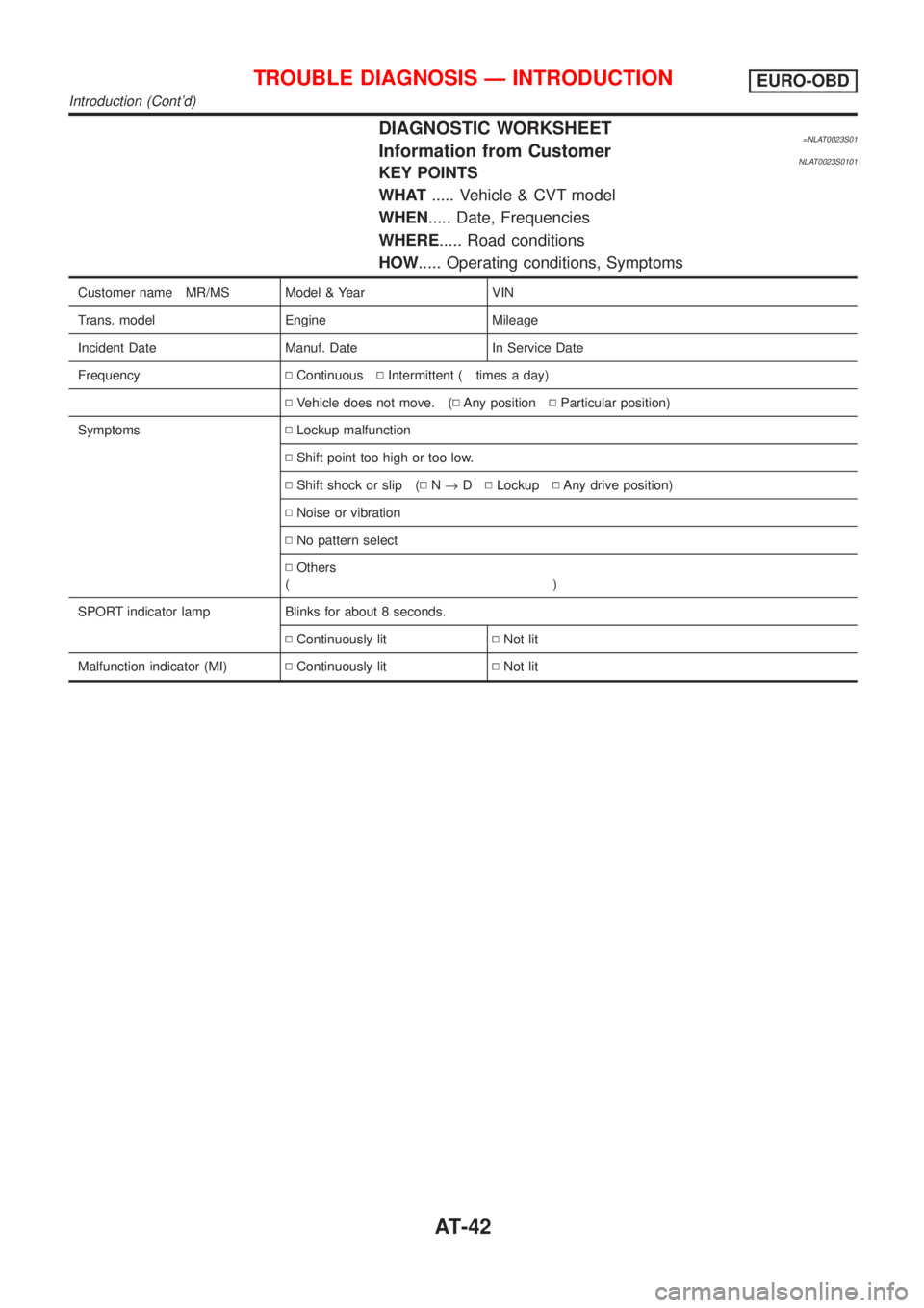
DIAGNOSTIC WORKSHEET=NLAT0023S01Information from CustomerNLAT0023S0101KEY POINTS
WHAT..... Vehicle & CVT model
WHEN..... Date, Frequencies
WHERE..... Road conditions
HOW..... Operating conditions, Symptoms
Customer name MR/MS Model & Year VIN
Trans. model Engine Mileage
Incident Date Manuf. Date In Service Date
FrequencyNContinuousNIntermittent ( times a day)
NVehicle does not move. (NAny positionNParticular position)
SymptomsNLockup malfunction
NShift point too high or too low.
NShift shock or slip (NN®DNLockupNAny drive position)
NNoise or vibration
NNo pattern select
NOthers
()
SPORT indicator lamp Blinks for about 8 seconds.
NContinuously litNNot lit
Malfunction indicator (MI)NContinuously litNNot lit
TROUBLE DIAGNOSIS Ð INTRODUCTIONEURO-OBD
Introduction (Cont'd)
AT-42
Page 47 of 3051
SAT631IA
SAT632I
SEF234G
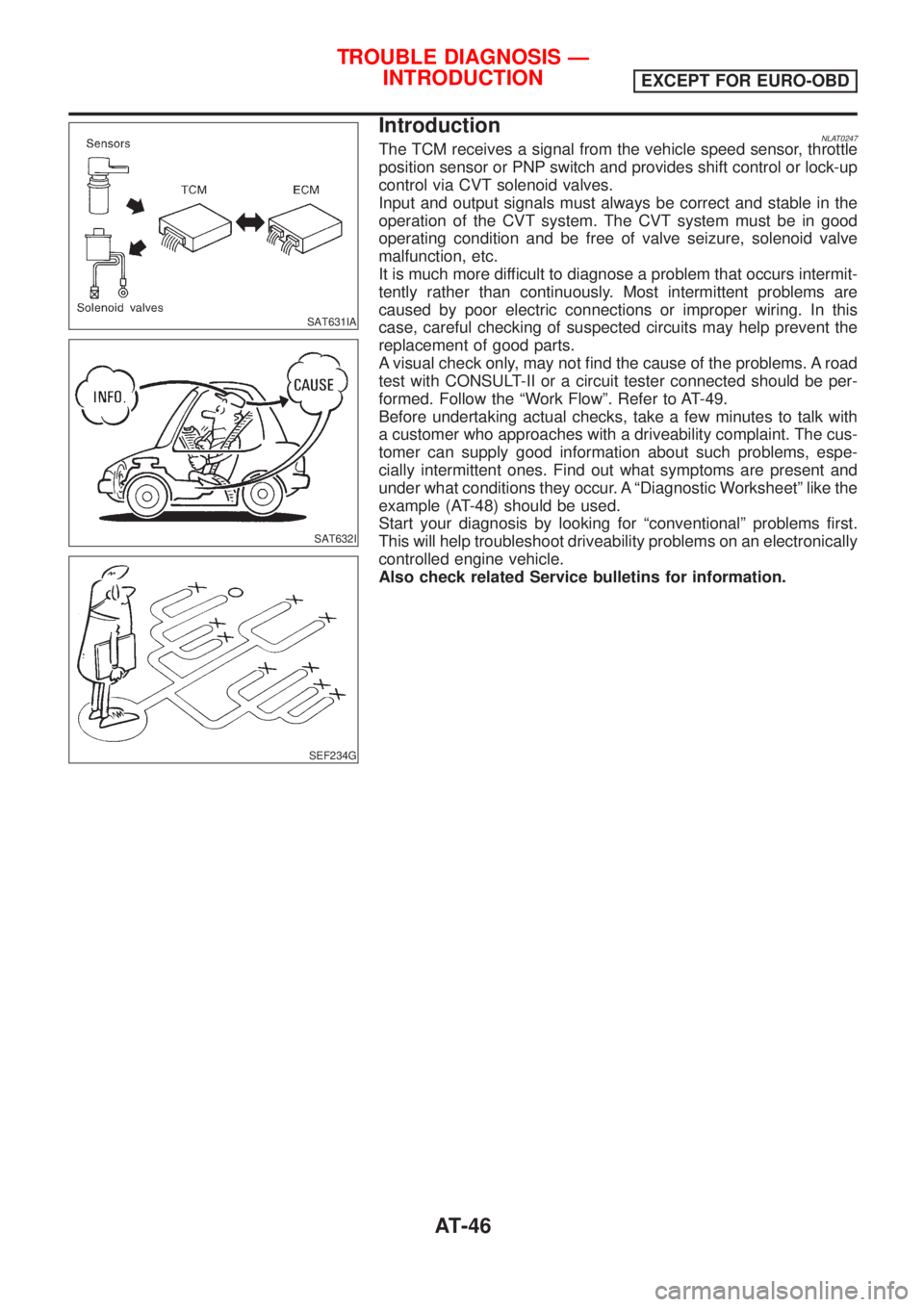
IntroductionNLAT0247The TCM receives a signal from the vehicle speed sensor, throttle
position sensor or PNP switch and provides shift control or lock-up
control via CVT solenoid valves.
Input and output signals must always be correct and stable in the
operation of the CVT system. The CVT system must be in good
operating condition and be free of valve seizure, solenoid valve
malfunction, etc.
It is much more difficult to diagnose a problem that occurs intermit-
tently rather than continuously. Most intermittent problems are
caused by poor electric connections or improper wiring. In this
case, careful checking of suspected circuits may help prevent the
replacement of good parts.
A visual check only, may not find the cause of the problems. A road
test with CONSULT-II or a circuit tester connected should be per-
formed. Follow the ªWork Flowº. Refer to AT-49.
Before undertaking actual checks, take a few minutes to talk with
a customer who approaches with a driveability complaint. The cus-
tomer can supply good information about such problems, espe-
cially intermittent ones. Find out what symptoms are present and
under what conditions they occur. A ªDiagnostic Worksheetº like the
example (AT-48) should be used.
Start your diagnosis by looking for ªconventionalº problems first.
This will help troubleshoot driveability problems on an electronically
controlled engine vehicle.
Also check related Service bulletins for information.
TROUBLE DIAGNOSIS Ð
INTRODUCTION
EXCEPT FOR EURO-OBD
AT-46