wheel NISSAN ALTIMA 1997 U13 / 1.G Owners Manual
[x] Cancel search | Manufacturer: NISSAN, Model Year: 1997, Model line: ALTIMA, Model: NISSAN ALTIMA 1997 U13 / 1.GPages: 203, PDF Size: 1.64 MB
Page 30 of 203

2Pre-driving checks and adjustments
Key .........................................................................2-2
Door locks ..............................................................2-2
Manual door lock ....................................................2-2
Power door lock .....................................................2-3
Child safety rear door lock .....................................2-4
Multi-remote control system (if so equipped).........2-4
Battery replacement ...............................................2-6
Hood release ..........................................................2-8
Glove box ...............................................................2-8
Trunk lid lock operation ..........................................2-9
Opener cancel lever for trunk lid..........................2-10
Fuel filler lid lock operation ..................................2-10
Fuel filler cap ........................................................2-11
Front seats ...........................................................2-12
Seat adjustment ...................................................2-12
Head restraints .....................................................2-14
Rear seat ..............................................................2-15
Supplemental restraint system (air bag
system) .................................................................2-16Supplemental air bag system...............................2-19
Warning labels......................................................2-21
Supplemental air bag warning light......................2-21
Seat belts .............................................................2-23
Precautions on seat belt usage ...........................2-23
Child safety...........................................................2-25
3-point type with retractor ....................................2-26
2-point type without retractor (center position
of rear seat) ..........................................................2-28
Seat belt extenders ..............................................2-30
Seat belt maintenance .........................................2-30
Child restraints for infants and small children......2-30
Top strap child restraint .......................................2-34
Tilting steering wheel ...........................................2-37
Outside mirror remote control ..............................2-37
Outside mirrors .....................................................2-37
Inside mirror .........................................................2-38
Vanity mirror .........................................................2-38
ZX
Page 45 of 203

This Supplemental Restraint System sec-
tion contains important information concern-
ing the driver and passenger supplemental
air bags. The Supplemental Restraint Sys-
tem Air Bag can help reduce impact force to
the driver and to the front passenger in
certain frontal collisions. The supplemental
air bags are designed tosupplementthe
crash protection provided by the driver and
front passenger seat belts and arenot a
substitutefor them. The seat belts should
always be correctly worn and the driver and
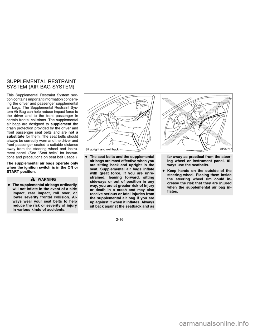
front passenger seated a suitable distance
away from the steering wheel and instru-
ment panel. (See ``Seat belts'' for instruc-
tions and precautions on seat belt usage.)
The supplemental air bags operate only
when the ignition switch is in the ON or
START position.
WARNING
cThe supplemental air bags ordinarily
will not inflate in the event of a side
impact, rear impact, roll over, or
lower severity frontal collision. Al-
ways wear your seat belts to help
reduce the risk or severity of injury
in various kinds of accidents.cThe seat belts and the supplemental
air bags are most effective when you
are sitting back and upright in the
seat. Supplemental air bags inflate
with great force. If you are unre-
strained, leaning forward, sitting
sideways or out of position in any
way, you are at greater risk of injury
or death in a crash and may also
receive serious or fatal injuries from
the supplemental air bag if you are
up against it when it inflates. Always
sit back against the seatback and asfar away as practical from the steer-
ing wheel or instrument panel. Al-
ways use the seatbelts.
cKeep hands on the outside of the
steering wheel. Placing them inside
the steering wheel rim could in-
crease the risk that they are injured
when the supplemental air bag in-
flates.
APD0717
SUPPLEMENTAL RESTRAINT
SYSTEM (AIR BAG SYSTEM)
2-16
ZX
Page 48 of 203

The driver supplemental air bag is located in
the center of the steering wheel; the front
passenger supplemental air bag is mounted in
the dashboard above the glove box. The
supplemental air bag system is designed to
inflate in higher severity frontal collisions, al-
though it may inflate if the forces in another
type of collision are similar to those of a higher
severity frontal impact. It may not inflate in
certain frontal collisions. Vehicle damage (or
lack of it) is not always an indication of proper
supplemental air bag operation.
When the supplemental air bag inflates, a
fairly loud noise may be heard, followed bythe release of smoke. This smoke is not
harmful and does not indicate a fire, but
care should be taken not to unintentionally
inhale it, as it may cause irritation and
choking. Those with a history of breathing
trouble should get fresh air promptly.
The supplemental air bags, along with the
use of seat belts, help to cushion the impact
force on the face and chest of the occupant.
They can help save lives and reduce seri-
ous injuries. However, an inflating supple-
mental air bag may cause facial abrasions
or other injuries. Supplemental air bags do
not provide restraint to the lower body.
Seat belts should be correctly worn and the
driver and passenger seated upright as far
as practical away from the steering wheel or
dashboard. Since the supplemental air bag
inflates quickly in order to help protect the
occupant, the force of the supplemental air
bag inflating can increase the risk of injury if
the occupant is too close to or is against the
supplemental air bag module during inflation.
The supplemental air bag deflates quickly
after a collision.
The supplemental air bags operate only
when the ignition switch is in the ON or
START position.
WARNING
c
Do not place any objects on the steer-
ing wheel pad or on the instrument
panel. Also, do not place any objects
between any occupant and the steer-
ing wheel or instrument panel. Such
objects may become dangerous pro-
jectiles and cause injury if the supple-
mental air bag inflates.
cRight after inflation, several supple-
mental air bag system components
will be hot. Do not touch them; you
may severely burn yourself.
APD0530
SUPPLEMENTAL AIR BAG
SYSTEM
2-19
ZX
Page 49 of 203

cNo unauthorized changes should be
made to any components or wiring of
the supplemental air bag system. This
is to prevent accidental inflation of the
supplemental air bag or damage to the
supplemental air bag system.
cDo not make unauthorized changes
to your vehicle's electrical system,
suspension system or front end
structure. This could affect proper
operation of the supplemental air
bag system.
c
Tampering with the supplemental air
bag system may result in serious per-
sonal injury. Tampering includes
changes to the steering wheel and the
instrument panel assembly by placing
material over the steering wheel pad
and above the dashboard, or by install-
ing additional trim material around the
supplemental air bag system.
cWork around and on the supplemen-
tal air bag system should be done by
an authorized NISSAN dealer. Instal-
lation of electrical equipment should
also be done by an authorized NIS-
SAN dealer. The yellow SRS wiringshould not be modified or discon-
nected. Unauthorized electrical test
equipment and probing devices
should not be used on the supple-
mental air bag system.
cThe SRS wiring harnesses are cov-
ered with yellow insulation either
just before the harness connectors
or over the complete harness for
easy identification.
When selling your vehicle, we request that
you inform the buyer about the supple-
mental air bag system and guide the buyer
to the appropriate sections in this Owner's
Manual.
2-20
ZX
Page 66 of 203

Tilt operation
Push the lock lever down and adjust the
steering wheel up or down to the desired
position.
Pull the lock lever up firmly to lock the
steering wheel in place.
WARNING
Do not adjust the steering wheel while
driving. You could lose control of your
vehicle and cause an accident.The outside mirror remote control only op-
erates when the ignition switch is in the
ACC or ON position.
Push the right or left side of the switch to
select the right or left outside mirror, then
adjust using the control lever.
WARNING
Objects viewed in the outside mirror on
the passenger side are closer than they
appear. Be careful when moving to the
right. Using only this mirror could cause
an accident. Use the inside mirror or
glance over your shoulder to properly
judge distances to other objects.
The driver and passenger outside mirrors
are foldable. Push the outside mirror back-
ward to fold it.
PD1028APD0529AIC0504
TILTING STEERING WHEEL OUTSIDE MIRROR REMOTE
CONTROLOUTSIDE MIRRORS
2-37
ZX
Page 96 of 203

MANUAL TRANSMISSION
The ignition switch includes an anti-theft
steering lock device.
The key can only be removed when the
ignition switch is in the LOCK position.
On manual transmission models, to turn the
ignition key to LOCK from ACC or ON, turn
the key to OFF and press in the key release
button, then turn the key to LOCK.
In order for the steering wheel to be locked,
it must be turned about 1/8 of a turn coun-
terclockwise from the straight up position.To lock the steering wheel, remove the
key. To unlock the steering wheel, insert
the key and turn it gently while rotating
the steering wheel slightly right and left.
WARNING
Never remove the key while driving. If
the key is removed, the steering wheel
will lock. This may cause the driver to
lose control of the vehicle and could
result in serious vehicle damage or
personal injury.
AUTOMATIC TRANSMISSION
On automatic transmission models the igni-
tion lock is designed so the key cannot be
turned to LOCK and removed until the shift
lever is moved to the P (Park) position.
When removing the key from the ignition,
make sure the shift lever is in the P (Park)
position.
When the key cannot be turned to the LOCK
position, proceed as follows to remove the
key:
1) Move the shift lever into the P (Park)
position.
ASD0022ASD0023
IGNITION SWITCH
4-4
ZX
Page 97 of 203

2) Turn the ignition key slightly in the ON
direction.
3) Turn the key toward the LOCK position.
4) Remove the key.
If the key is removed from the ignition
switch, the shift lever cannot be moved from
P (Park).The shift lever can be moved if
the ignition switch is in the ACC posi-
tion. The shift lever can also be moved if
the ignition switch is in the ON position
and the foot brake pedal is depressed.
There is an OFF position in between LOCK
and ACC, although it does not show on the
key cylinder. When the ignition is in OFF the
steering wheel is not locked.
In order for the steering wheel to be locked, it
must be turned about 1/8 of a turn counter-
clockwise from the straight up position, and
the key must be removed from the ignition.
To lock the steering wheel, remove the
key. To unlock the steering wheel, insert
the key and turn it gently while rotating
the steering wheel slightly right and left.
WARNING
Never remove the key while driving. If
the key is removed, the steering wheel
will lock. This may cause the driver to
lose control of the vehicle and could
result in serious vehicle damage or
personal injury.
Key positions
LOCK Normal parking position (0)
OFF (1)
The engine can be turned off without locking
the steering wheel.
ACC (Accessories) (2)
This position activates electrical accesso-
ries such as the radio when the engine is
not running.
ON Normal operating position (3)
This position turns on the ignition system
and the electrical accessories.
START (4)
This position activates the starter motor,
which starts the engine.cMake sure the area around the vehicle is
clear.
cMaintenance items listed here should be
checked periodically, for example, each
time you check engine oil.
cCheck that all windows and lights are
clean.
cVisually inspect tires for their appearance
and condition. Also check tires for proper
inflation.
cLock all doors.
cPosition seat and adjust head restraints.
cAdjust inside and outside mirrors.
cFasten seat belts and ask all passengers
to do likewise.
cCheck the operation of warning lights
when key is turned to the ON (3) position.
BEFORE STARTING THE
ENGINE
4-5
ZX
Page 105 of 203

To reset at a slower cruising speed,use
one of the following three methods:
a) Lightly tap the brake pedal. When the
vehicle attains the desired speed, push
the COAST/SET switch and release it.
b) Push and hold the COAST/SET switch.
Release the switch when the vehicle
slows to the desired speed.
c) Push and quickly release the
COAST/SET switch. Each time you do
this, the set speed decreases by about 1
MPH (1.6 km/h).
To resume the preset speed,push and re-
lease the RESUME switch. The vehicle returns
to the last set cruising speed when the vehicle
speed is over 30 MPH (48 km/h).
Precautions
cIf the cruise control system malfunctions,
it cancels automatically. The cruise indi-
cator light in the instrument panel then
blinks to warn the driver.
cIf the cruise indicator light blinks, turn the
cruise control main switch off and have
the system checked by your NISSAN
dealer.cThe cruise indicator light may blink when
the cruise control main switch is turned
ON while pushing the RES/ACCEL,
COAST/SET, or CANCEL switch (lo-
cated on the steering wheel). To properly
set the cruise control system, perform the
preceding steps in the order indicated.
WARNING
Do not use the cruise control when
driving under the following conditions:
cit is not possible to keep the vehicle
at a set speed.
cin heavy traffic or in traffic that var-
ies in speed.
con winding or hilly roads.
con slippery roads (rain, snow, ice,
etc.).
cin very windy areas.
Doing so could cause a loss of vehicle
control and result in an accident.
CAUTION
On manual transmission models, do
not shift into neutral without depress-
ing the clutch pedal when the cruise
control is on. Should this occur, de-
press the clutch pedal and turn the
main switch off immediately. Failure to
do so may cause engine damage.
4-13
ZX
Page 106 of 203

During the first 1,000 miles (1,600 km),
follow these recommendations for the future
reliability and economy of your new vehicle.
Failure to follow these recommendations
may result in vehicle damage or shortened
engine life.
cDo not drive over 55 MPH (90 km/h) and
do not run the engine over 4,000 rpm.
Avoid driving for long periods at constant
speed, either fast or slow.
cDo not accelerate at full throttle in any
gear.
cAvoid quick starts.
cAvoid hard braking as much as possible.
cDo not tow a trailer for the first 500 miles
(800 km).cAccelerate slowly and smoothly. Main-
tain cruising speeds with a constant ac-
celerator position.
cDrive at moderate speeds on the high-
way. Driving at high speed lowers fuel
economy.
cAvoid unnecessary stopping and brak-
ing. Maintain a safe distance behind
other vehicles.
cUse a proper gear range which suits road
conditions. On level roads, shift into high
gear as soon as possible.
cAvoid unnecessary engine idling.cKeep your engine tuned up.
cFollow the recommended periodic main-
tenance schedule.
cKeep the tires inflated at the correct
pressure. Low pressure increases tire
wear and wastes fuel.
cKeep the front wheels in correct align-
ment. Improper alignment increases tire
wear and lowers fuel economy.
cAir conditioner operation lowers fuel
economy. Use the air conditioner only
when necessary.
cWhen cruising at highway speeds, it is
more economical to use the air condi-
tioner and leave the windows closed to
reduce drag.
SD1001M
BREAK-IN SCHEDULE INCREASING FUEL
ECONOMY
4-14
ZX
Page 107 of 203

WARNING
Do not park the vehicle over flammable
materials such as dry grass, waste pa-
per or rags. They may ignite and cause
a fire.
1. Firmly apply the parking brake.
2.Manual transmission models:
Place the gearshift lever in the R (Re-
verse) position. When parking on an up-
hill grade, place the gearshift lever in 1
(First) gear.Automatic transmission models:
Move the gearshift lever to the P (Park)
position.
WARNING
Safe parking procedures require that
both the parking brake be set and the
transmission placed into P position
(automatic) or in the appropriate gear
(manual). Failure to do so could cause
the vehicle to move unexpectedly or
roll away and result in an accident.
Make sure the shift lever has beenpushed as far forward as it can go and
cannot be moved without depressing
the button at the end of the lever.
3. To help prevent the vehicle from rolling
into traffic when parked on an incline, it is
a good practice to turn the wheels as
illustrated.
cHEADED DOWNHILL WITH CURB:
s1
Turn the wheels into the curb and move
the vehicle forward until the curb side
wheel gently touches the curb.
cHEADED UPHILL WITH CURB:
s2
Turn the wheels away from the curb and
move the vehicle back until the curb side
wheel gently touches the curb.
cHEADED UPHILL OR DOWNHILL, NO
CURB:
s3
Turn the wheels toward the side of the
road so the vehicle will move away from
the center of the road if it moves.
4. Turn the ignition key to the LOCK posi-
tion and remove the key.
SD1006M
PARKING/PARKING ON HILLS
4-15
ZX