automatic transmission NISSAN ALTIMA 2023 Owners Manual
[x] Cancel search | Manufacturer: NISSAN, Model Year: 2023, Model line: ALTIMA, Model: NISSAN ALTIMA 2023Pages: 644, PDF Size: 4.12 MB
Page 121 of 644
Release Parking Brake
This warning appears when the parking
brake is set and the vehicle is driven.
Shif t to Park
This warning appears when the ignition
switch is in the AUTO ACC or OFF position
and the shif t lever is not in the P (Park)
position. Also, a chime sounds when the
ignition switch is in the AUTO ACC or OFF
position.
If this warning appears, move the shif t lever
to the P (Park) position and start the engine.
Shipping Mode On Push Storage Fuse
This warning may appear if the extended
storage switch is not pushed in. When this
warning appears, push in the extended
storage switch to turn off the warning. For
additional information, see “Extended stor-
age switch” (P. 2-70).
Tire Pressure Low - Add Air
This warning appears when the low tire
pressure warning light in the meter illumi-
nates and low tire pressure is detected. The
warning appears each time the ignition
switch is placed in the ON position as long
as the low tire pressure warning light re-mains illuminated. If this warning appears,
stop the vehicle and adjust the tire pres-
sures of all four tires to the recommended
COLD tire pressure shown on the Tire and
Loading Information label. For additional
information, see “Low tire pressure warning
light” (P. 2-13) and “Tire Pressure Monitoring
System (TPMS)” (P. 5-5).
Transmission Shif t Position
indicator
This indicator shows the transmission shif t
position.
Service CVT
This warning appears when there is a
problem with the CVT system. If this
warning appears, have the system
checked. It is recommended that you visit a
NISSAN dealer for this service.
CVT hot Power reduced
This transmission has a high fluid tem-
perature protection mode. If the fluid tem-
perature becomes too high (for example,
climbing steep grades in high tempera-
tures with heavy loads, such as when tow-
ing a trailer), engine power and, under
some conditions, vehicle speed will be de-
creased automatically to reduce thechance of transmission damage. Vehicle
speed can be controlled with the accelera-
tor pedal, but the engine and vehicle speed
may be reduced.
WARNING
When the high fluid temperature pro-
tection mode operation occurs, vehicle
speed may be gradually reduced. The
reduced speed may be lower than
other traffic, which could increase the
chance of a collision. Be especially
careful when driving. If necessary, pull
to the side of the road at a safe place
and allow the transmission to return to
normal operation; or have it repaired if
necessary.
CVT (AT) Malfunction Service now
This warning appears when there is a
problem with the CVT system. If this
warning comes on, have the system
checked. It is recommended that you visit a
NISSAN dealer for this service.
CVT (AT) Stop the vehicle
This message appears 30 seconds before
the vehicle is shut down due to an above
normal operating transmission tempera-
ture. The Malfunction Indicator Light (MIL)
Instruments and controls2-31
Page 138 of 644
Shipping Mode On Push Storage Fuse
This warning may appear if the extended
storage switch is not pushed in. When this
warning appears, push in the extended
storage switch to turn off the warning. For
additional information, see “Extended stor-
age switch” (P. 2-70).
Timer Alert Time for a
break?
This message appears when the set time
is reached. This time can be set up to six
hours. For additional information, see
“Driver Assistance” (P. 2-38)
Tire Pressure Low - Add Air
This warning appears when the low tire
pressure warning light in the meter illumi-
nates and low tire pressure is detected. The
warning appears each time the ignition
switch is placed in the ON position as long
as the low tire pressure warning light re-
mains illuminated. If this warning appears,
stop the vehicle and adjust the tire pres-
sures of all four tires to the recommended
COLD tire pressure shown on the Tire and
Loading Information label. For additional
information, see “Low tire pressure warning
light” (P. 2-13) and “Tire Pressure Monitoring
System (TPMS)” (P. 5-5).
Transmission Shif t Position
indicator
This indicator shows the transmission shif t
position.
AWD Error: See Owner’s
Manual
This warning appears when the All-Wheel
Drive (AWD) system is not functioning prop-
erly while the engine is running.
AWD High Temp. Stop
Vehicle
This warning may appear while trying to
free a stuck vehicle due to increased oil
temperature. The driving mode may
change to 2-Wheel Drive (2WD). If this
warning is displayed, stop the vehicle with
the engine idling, as soon as it is safe to do
so. Then if the warning turns off, you can
continue driving.
Tire Size Incorrect See
Owner’s Manual
This warning may appear if there is a large
difference between the diameters of the
front and rear wheels. Pull off the road in a
safe area, with the engine idling. Check that
all the tire sizes are the same, that the tirepressure is correct and that the tires are
not excessively worn.
CVT (AT) Malfunction
Service now
This warning appears when there is a
problem with the CVT system. If this
warning appears, have the system
checked. It is recommended that you visit a
NISSAN dealer for this service.
CVT (AT) hot Power reduced
This transmission has a high fluid tem-
perature protection mode. If the fluid tem-
perature becomes too high (for example,
climbing steep grades in high tempera-
tures with heavy loads, such as when tow-
ing a trailer), engine power and, under
some conditions, vehicle speed will be de-
creased automatically to reduce the
chance of transmission damage. Vehicle
speed can be controlled with the accelera-
tor pedal, but the engine and vehicle speed
may be reduced.
2-48Instruments and controls
Page 139 of 644
WARNING
When the high fluid temperature pro-
tection mode operation occurs, vehicle
speed may be gradually reduced. The
reduced speed may be lower than
other traffic, which could increase the
chance of a collision. Be especially
careful when driving. If necessary, pull
to the side of the road at a safe place
and allow the transmission to return to
normal operation; or have it repaired if
necessary.
CVT (AT) Stop the vehicle
This message appears 30 seconds before
the vehicle is shut down due to an above
normal operating transmission tempera-
ture. The Malfunction Indicator Light (MIL)
and malfunction warning (red) will illumi-
nate. Have the system checked. It is recom-
mended that you visit a NISSAN dealer im-
mediately for this service.
Automatic Emergency
Braking (AEB) with
Pedestrian Detection
emergency warning
indicator
This indicator appears along, with an au-
dible warning, when the system detects
the possibility of a forward collision.
For additional information, see “Automatic
Emergency Braking (AEB) with Pedestrian
Detection” (P. 5-135).
Blind Spot Warning (BSW)
indicator
This indicator appears when the BSW sys-
tem is engaged.
For additional information, see “Blind Spot
Warning (BSW)” (P. 5-46).
Cruise control indicator
This indicator shows the cruise control sys-
tem status.
When cruise control is activated, a green
circle will appear to indicate it is set. The
vehicle information display will also display
the speed the cruise control was set at. If
you accelerate past the set speed, the
speed will blink until you either cancel
cruise control or go back to the set speed. If cruise control is on and canceled, the
speed will be displayed to show the speed
the vehicle will return to if the resume but-
ton is activated.
Currently not available
This message may appear when the ProPI-
LOT Assist system or the Intelligent Lane
Intervention (I-LI) system is engaged.
Under the following conditions, the ProPI-
LOT Assist or the Intelligent Lane Interven-
tion (I-LI) system is automatically canceled:
• When the VDC system is turned off
The above system cannot be used in some
situations (VDC operates, wheel slip and
VDC system is off.)
Driver Attention Alert
Malfunction
This warning appears when the Intelligent
Driver Alertness (I-DA) system is not func-
tioning properly. For additional information,
see “Intelligent Driver Alertness (I-DA)”
(P. 5-162).
Driver Attention Alert—
TakeaBreak?
This alert appears when the system has
detected that the driver may be displaying
fatigue or a lack of attention.
Instruments and controls2-49
Page 173 of 644
4. At the receiver located on the garagedoor opener motor in the garage, locate
the “learn” or “smart” button (the name
and color of the button may vary by
manufacturer but it is usually located
near where the hanging antenna wire is
attached to the unit). If there is difficulty
locating the button, reference the ga-
rage door opener’s manual.
5. Press and release the “learn” or “smart” button.
NOTE:Once the button is pressed, you have ap-
proximately 30 seconds to initiate the
next step.
6. Return to the vehicle and firmly press and hold the trained HomeLink® button
for 2 seconds and release. Repeat the
“press/hold/release” sequence up to
three times to complete the training
process. HomeLink® should now acti-
vate your rolling code equipped device.
7. If you have any questions or are having difficulty programming your HomeLink®
buttons, refer to the HomeLink® web site
at: www.homelink.com or call
1-800-355-3515.
PROGRAMMING HOMELINK® FOR
CANADIAN CUSTOMERS AND GATE
OPENERS
Canadian radio-frequency laws require
transmitter signals to “time-out” (or quit)
af ter several seconds of transmission –
which may not be long enough for
HomeLink® to pick up the signal during
training. Similar to this Canadian law, some
U.S. gate operators are designed to “tim-
eout” in the same manner.
If you live in Canada or you are having diffi-
culties training a gate operator orgarage
door opener by using the “Training” proce-
dures, replace “Programming HomeLink®”
step 2 with the following:
NOTE:
When programming a garage door
opener, etc., unplug the device during
the “cycling” process to prevent possible
damage to the garage door opener
components.
1. For additional information, see “Pro-
gramming HomeLink®” step 1, (P. 2-81). 2. Using both hands, simultaneously press
and hold the desired HomeLink® button
and the hand-held transmitter button.
During training, your hand-held trans-
mitter may automatically stop transmit-
ting. Continue to press and hold the de-
sired HomeLink® button while you press
and re-press (“cycle”) your hand-held
transmitter every 2 seconds until the
frequency signal has been learned. The
HomeLink® indicator light will flash
slowly and then rapidly af ter several
seconds upon successful training. DO
NOT release until the HomeLink® indica-
tor light flashes slowly and then rapidly.
When the indicator light flashes rapidly,
both buttons may be released. The rapid
flashing indicates successful training.
Proceed with “Programming
HomeLink®” step 3 to complete.
If the device was unplugged during the
programming procedure, remember to
plug it back in when programming is
completed.
Instruments and controls2-83
Page 182 of 644
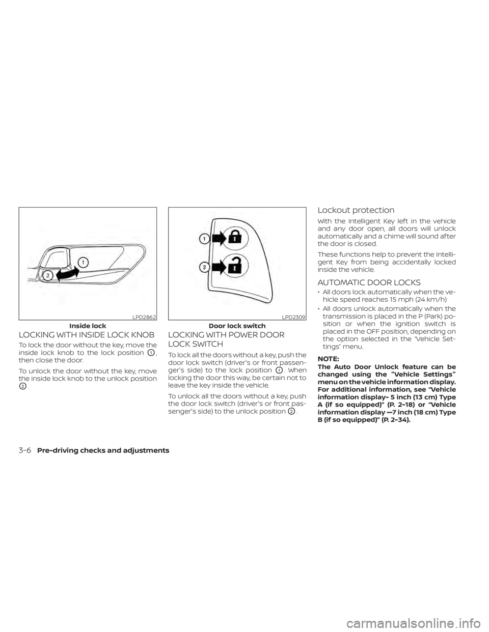
LOCKING WITH INSIDE LOCK KNOB
To lock the door without the key, move the
inside lock knob to the lock position
O1,
then close the door.
To unlock the door without the key, move
the inside lock knob to the unlock position
O2.
LOCKING WITH POWER DOOR
LOCK SWITCH
To lock all the doors without a key, push the
door lock switch (driver's or front passen-
ger's side) to the lock position
O1. When
locking the door this way, be certain not to
leave the key inside the vehicle.
To unlock all the doors without a key, push
the door lock switch (driver's or front pas-
senger's side) to the unlock position
O2.
Lockout protection
With the Intelligent Key lef t in the vehicle
and any door open, all doors will unlock
automatically and a chime will sound af ter
the door is closed.
These functions help to prevent the Intelli-
gent Key from being accidentally locked
inside the vehicle.
AUTOMATIC DOOR LOCKS
• All doors lock automatically when the ve- hicle speed reaches 15 mph (24 km/h)
• All doors unlock automatically when the transmission is placed in the P (Park) po-
sition or when the ignition switch is
placed in the OFF position, depending on
the option selected in the “Vehicle Set-
tings” menu.
NOTE:The Auto Door Unlock feature can be
changed using the "Vehicle Settings"
menu on the vehicle information display.
For additional information, see “Vehicle
information display- 5 inch (13 cm) Type
A (if so equipped)” (P. 2-18) or “Vehicle
information display —7 inch (18 cm) Type
B (if so equipped)” (P. 2-34).
LPD2862
Inside lock
LPD2309
Door lock switch
3-6Pre-driving checks and adjustments
Page 296 of 644
5 Starting and driving
Precautions when starting and driving..........5-4
Exhaust gas (carbon monoxide) ..............5-4
Three-way catalyst ...........................5-4
Tire Pressure Monitoring System
(TPMS) .......................................5-5
Avoiding collision and rollover ................5-9
Off-roadrecovery ............................5-9
Rapid air pressure loss .......................5-9
Drinking alcohol/drugs and driving ..........5-10
Driving safety precautions ...................5-10
Push-button ignition switch ....................5-13
Operating range ............................ 5-14
Push-button ignition switch positions .......5-14
Emergency engine shut off ..................5-15
NISSAN Intelligent Key® battery
discharge ................................... 5-15
NISSAN Vehicle Immobilizer System .........5-16
Before starting the engine .....................5-16
Starting the engine ............................. 5-16
Remote Engine Start ........................ 5-17
Driving the vehicle .............................. 5-18
Continuously Variable Transmission
(CVT) ........................................ 5-18
Parking brake .................................. 5-25
Manual parking brake (pedal type) ...........5-25
Electronic parking brake (switch type) .......5-25 Automatic brake hold (if so equipped)
..........5-27
How to activate/deactivate the
automatic brake hold function ..............5-28
How to use the automatic brake hold
function ..................................... 5-29
Traffic Sign Recognition (TSR) (if so equipped) . . . 5-30 System operation ........................... 5-31
Turning the Traffic Sign Recognition
(TSR) system on and off .....................5-32
System temporarily unavailable .............5-32
System malfunction ......................... 5-32
System maintenance .......................5-33
Lane Departure Warning (LDW) .................5-33
LDW system operation ......................5-34
How to enable/disable the LDW system .....5-36
LDW system limitations .....................5-38
System temporarily unavailable .............5-39
System malfunction ......................... 5-39
System maintenance .......................5-39
Intelligent
Lane Intervention (I-LI)
(if so equipped) ................................. 5-40
I-LI system operation ........................ 5-41
How to enable/disable the I-LI system ......5-42
I-LI system limitations .......................5-43
System temporarily unavailable .............5-44
System malfunction ......................... 5-45
Page 314 of 644
CONTINUOUSLY VARIABLE
TRANSMISSION (CVT)
WARNING
• Do not depress the accelerator pedal
while shif ting from P (Park) or N (Neu-
tral) to R (Reverse), D (Drive), L (Low) or
manual shif t mode (if so equipped).
Always depress the brake pedal until
shif ting is completed. Failure to do so
could cause you to lose control and
have an accident.
• Cold engine idle speed is high, so use
caution when shif ting into a forward
or reverse gear before the engine has
warmed up.
• Do not downshif t abruptly on slip-
pery roads. This may cause a loss of
control.
• Never shif t to either the P (Park) or R
(Reverse) position while the vehicle is
moving forward and P (Park) or D
(Drive) position while the vehicle is
reversing. This could cause an acci-
dent or damage the transmission.
CAUTION
• Except in an emergency, do not shif t
to the N (Neutral) position while driv-
ing. Coasting with the transmission
in the N (Neutral) position may cause
serious damage to the transmission.
• To avoid possible damage to your ve-
hicle, when stopping the vehicle on
an uphill grade, do not hold the ve-
hicle by depressing the accelerator
pedal. The foot brake should be used
for this purpose.
The CVT in your vehicle is electronically
controlled to produce maximum power
and smooth operation.
Follow these procedures for maximum ve-
hicle performance and driving enjoyment.
NOTE:
Engine power may be automatically re-
duced to protect the CVT if the engine
speed increases quickly when driving on
slippery roads or while being tested on
some dynamometers.
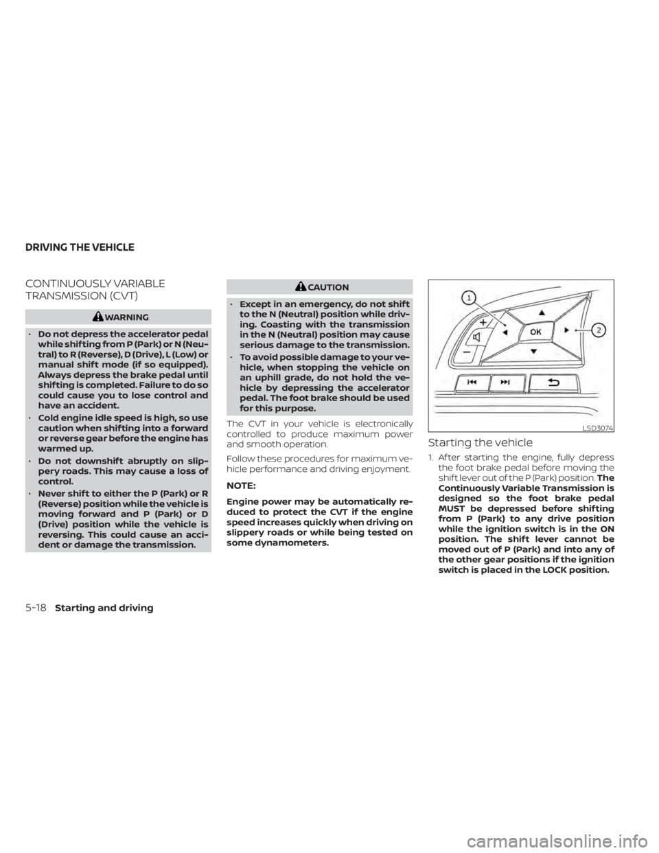
Starting the vehicle
1. Af ter starting the engine, fully depress the foot brake pedal before moving the
shif t lever out of the P (Park) position. The
Continuously Variable Transmission is
designed so the foot brake pedal
MUST be depressed before shif ting
from P (Park) to any drive position
while the ignition switch is in the ON
position. The shif t lever cannot be
moved out of P (Park) and into any of
the other gear positions if the ignition
switch is placed in the LOCK position.
LSD3074
DRIVING THE VEHICLE
5-18Starting and driving
Page 318 of 644
M4 (4th), M3 (3rd) and M2 (2nd)
Use for hill climbing or engine braking on
downhill grades.
M1 (1st)
Use this position when climbing steep hills
slowly or driving slowly through deep snow,
sand or mud, or for maximum engine brak-
ing on steep downhill grades.
• Remember not to drive at high speeds forextended periods of time in lower than
the 8th range. This reduces fuel economy.
When shif ting up
Use the + (up) side paddle shif ter. (Shif ts to
higher range.)
When shif ting down
Use the − (down) side paddle shif ter. (Shif ts
to lower range.)
When canceling the manual shif t mode
To cancel manual shif t mode, push the
drive sport mode switch on the shif t lever
or press and hold either paddle shif ter.
• In the manual shif t mode, the trans-
mission may not shif t to the selected
gear. This helps maintain driving per-
formance and reduces the chance of
vehicle damage or loss of control. •
In the manual shif t mode, the trans-
mission may shif t up automatically to a
higher range than selected if the en-
gine speed is too high. When the ve-
hicle speed decreases, the transmis-
sion automatically shif ts down and
shif ts to 1st gear before the vehicle
comes to a stop.
• Continuously Variable Transmission (CVT) operation is limited to automatic
drive mode when CVT fluid temperature
is extremely low even if manual shif t
mode is selected. This is not a malfunc-
tion. When CVT fluid warms up, manual
mode can be selected.
• When the CVT fluid temperature is high, the shif t range may upshif t in lower rpm
than usual. This is not a malfunction.
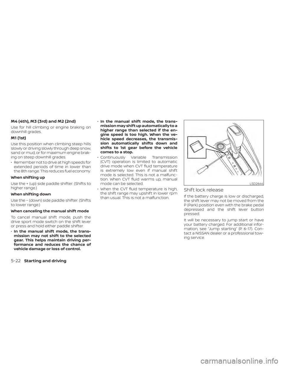
Shif t lock release
If the battery charge is low or discharged,
the shif t lever may not be moved from the
P (Park) position even with the brake pedal
depressed and the shif t lever button
pressed.
It will be necessary to jump start or have
your battery charged. For additional infor-
mation, see “Jump starting” (P. 6-17). Con-
tact a NISSAN dealer or a professional tow-
ing service.
LSD2644
5-22Starting and driving
Page 320 of 644
Each time the engine is started, or when
the shif t lever is shif ted to any position
other than D (Drive), the drive sport mode
will automatically turn off.
Accelerator downshif t
— in D (Drive) position —
For passing or hill climbing, depress the
accelerator pedal to the floor. This shif ts
the transmission down into a lower gear,
depending on the vehicle speed.
High fluid temperature protection
mode
This transmission has a high fluid tem-
perature protection mode. If the fluid tem-
perature becomes too high (for example,
when climbing steep grades in high tem-
peratures with heavy loads, such as when
towing a trailer), engine power and, under
some conditions, vehicle speed will be de-
creased automatically to reduce the
chance of transmission damage. Vehicle
speed can be controlled with the accelera-
tor pedal, but the engine and vehicle speed
may be limited.
Fail-safe
If the vehicle is driven under extreme
conditions, such as excessive wheel
spinning and subsequent hard braking,
the fail-safe system may be activated.
The Malfunction Indicator Light (MIL)
may come on to indicate the fail-safe
mode is activated. For additional infor-
mation, see “Malfunction Indicator Light
(MIL)” (P. 2-15). This will occur even if all
electrical circuits are functioning prop-
erly. In this case, place the ignition switch
in the OFF position and wait for 10 sec-
onds. Then push the switch back to the
ON position. The vehicle should return to
its normal operating condition. If it does
not return to its normal operating condi-
tion, have the transmission checked. It is
recommended that you visit a NISSAN
dealer for this service.
WARNING
When the high fluid temperature pro-
tection mode or fail-safe operation oc-
curs, vehicle speed may be gradually
reduced. The reduced speed may be
lower than other traffic, which could in-
crease the chance of a collision. Be es-
pecially careful when driving. If neces-
sary, pull to the side of the road at a safe
place and allow the transmission to re-
turn to normal operation, or have it re-
paired if necessary.
5-24Starting and driving
Page 475 of 644
When the vehicle is stopped on a hill, the hill
start assist system automatically keeps
the brakes applied to help prevent the ve-
hicle from rolling backward in the time it
takes the driver to release the brake pedal
and apply the accelerator.
The hill start assist system will operate au-
tomatically under the following conditions:
• The transmission is shif ted to a forwardor reverse gear.
• The vehicle is stopped completely on a hill by applying the brake. The maximum
holding time is 2 seconds. Af ter 2 sec-
onds the vehicle will begin to roll back and
the hill start assist system will stop oper-
ating completely.
The hill start assist system will not operate
when the shif t lever is placed in the N (Neu-
tral) or P (Park) position or on a flat and level
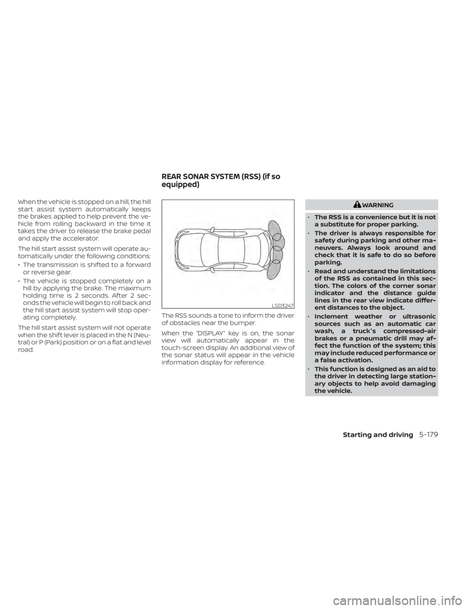
road. The RSS sounds a tone to inform the driver
of obstacles near the bumper.
When the “DISPLAY” key is on, the sonar
view will automatically appear in the
touch-screen display. An additional view of
the sonar status will appear in the vehicle
information display for reference.WARNING
• The RSS is a convenience but it is not
a substitute for proper parking.
• The driver is always responsible for
safety during parking and other ma-
neuvers. Always look around and
check that it is safe to do so before
parking.
• Read and understand the limitations
of the RSS as contained in this sec-
tion. The colors of the corner sonar
indicator and the distance guide
lines in the rear view indicate differ-
ent distances to the object.
• Inclement weather or ultrasonic
sources such as an automatic car
wash, a truck's compressed-air
brakes or a pneumatic drill may af-
fect the function of the system; this
may include reduced performance or
a false activation.
• This function is designed as an aid to
the driver in detecting large station-
ary objects to help avoid damaging
the vehicle.
LSD3247
REAR SONAR SYSTEM (RSS) (if so
equipped)
Starting and driving5-179