NISSAN ALTIMA COUPE 2011 D32 / 4.G Owners Manual
ALTIMA COUPE 2011 D32 / 4.G
NISSAN
NISSAN
https://www.carmanualsonline.info/img/5/257/w960_257-0.png
NISSAN ALTIMA COUPE 2011 D32 / 4.G Owners Manual
Trending: maintenance schedule, door lock, lumbar support, coolant level, set clock, start stop button, rear view mirror
Page 391 of 446
Sedan
1. Rear map light
2. Front map light
3. Step light
4. Headlamp assembly
5. Fog light (if so equipped)
6. High-mount stoplight (if so equipped)
7. Trunk light
8. Spoiler mounted stoplight(if so equipped)
9. Rear combination light
10. License plate light
11. Mirror-mounted turn signal light
(if so equipped)
WDI0680
8-32Maintenance and do-it-yourself
Page 392 of 446
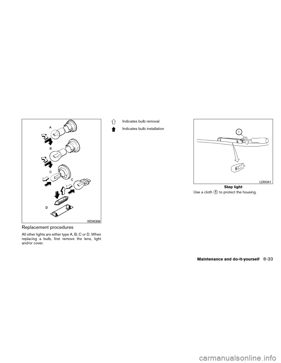
Replacement procedures
All other lights are either type A, B, C or D. When
replacing a bulb, first remove the lens, light
and/or cover.
Indicates bulb removal
Indicates bulb installationUse a cloth
�1to protect the housing.
WDI0306
Step light
LDI0341
Maintenance and do-it-yourself8-33
Page 393 of 446
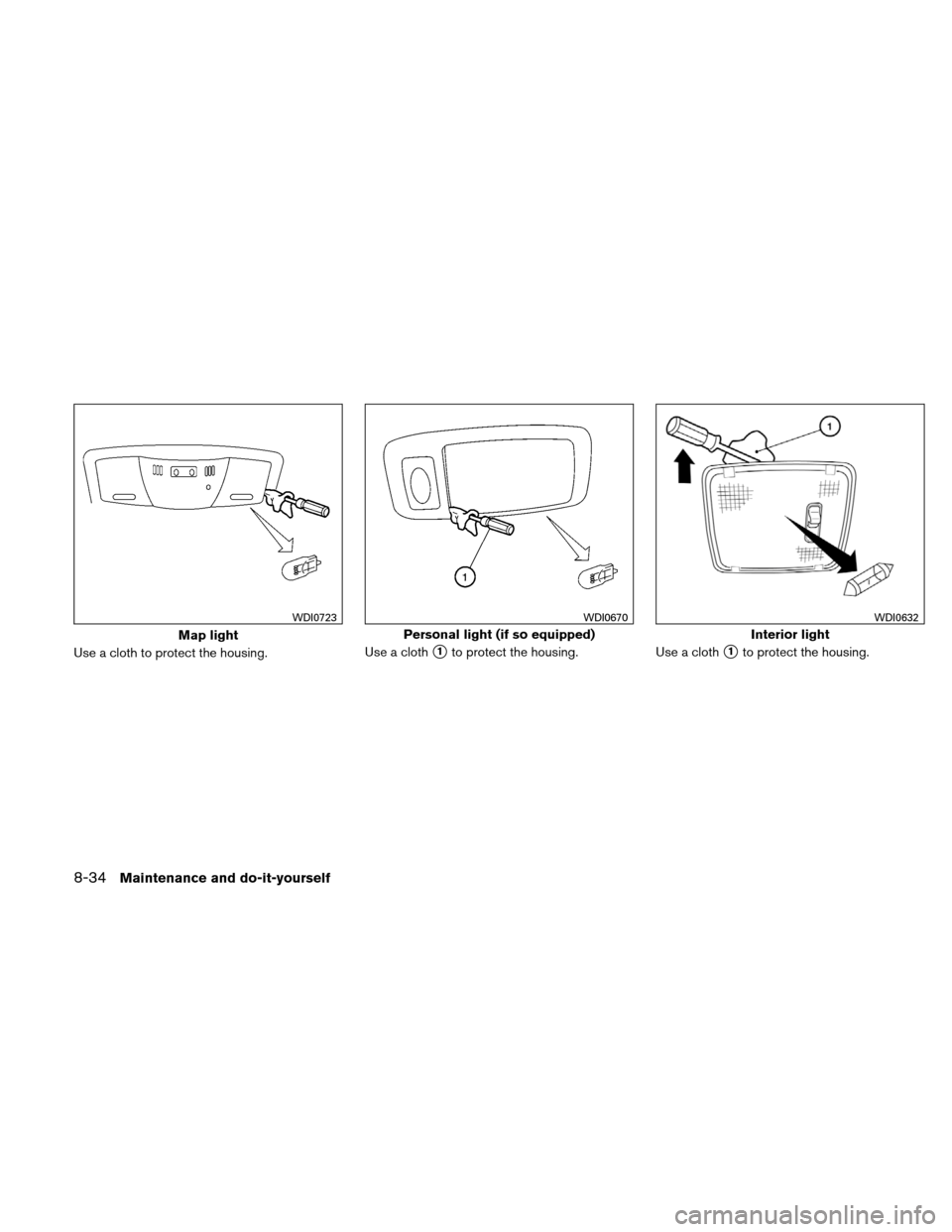
Use a cloth to protect the housing.Use a cloth�1to protect the housing.
Use a cloth�1to protect the housing.
Map light
WDI0723
Personal light (if so equipped)
WDI0670
Interior light
WDI0632
8-34Maintenance and do-it-yourself
Page 394 of 446
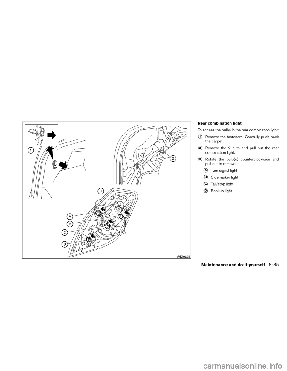
Rear combination light
To access the bulbs in the rear combination light:
�1Remove the fasteners. Carefully push back
the carpet.
�2Remove the 2 nuts and pull out the rear
combination light.
�3Rotate the bulb(s) counterclockwise and
pull out to remove:
�ATurn signal light
�BSidemarker light
�CTail/stop light
�DBackup light
WDI0635
Maintenance and do-it-yourself8-35
Page 395 of 446
CAUTION
Never force the covers into place because
the hinge pins can be damaged. Follow
the removal and installation instructions
to prevent inoperability of the covers.
Trunk light
WDI0343
High-mounted stoplight (rear window)
WDI0320
UPPER TETHER ANCHOR/KEY
CYLINDER COVERS
8-36Maintenance and do-it-yourself
Page 396 of 446
REMOVING COVERS FROM REAR
PARCEL SHELF
Remove the top tether anchor cover or key cylin-
der cover as follows:1. Lift the cover to the full open position. 2. Rotate the cover in the direction shown,
disengaging the hinge at
�1and slide the
second pin from the hinge
�2and remove
the cover.
INSTALLING COVERS TO REAR
PARCEL SHELF
CAUTION
Make sure that the hinge is completely
aligned with the pin. If the pin is forced
into position, it may break.
Install the top tether anchor cover or key cylinder
cover as follows: 1. With the pin on one end kept free of its hinge
�1, align the pin of the other end and slide it
into the hinge
�2.
LDI2009LDI2010LDI2011
Maintenance and do-it-yourself8-37
Page 397 of 446

2. With the first pin in position�2, align the
second pin with its hinge slot
�1and push
down on the cover to completely engage it.
A snap sound will be heard. 3. Close the cover. If you have a flat tire, see “Flat tire” in the
“In case of emergency” section of this
manual.
TIRE PRESSURE
Tire Pressure Monitoring System
(TPMS)
This vehicle is equipped with the Tire
Pressure Monitoring System (TPMS) . It
monitors tire pressure of all tires except
the spare. When the low tire pressure
warning light is lit and the CHECK TIRE
PRESSURE warning appears in the ve-
hicle information display, one or more of
your tires is significantly under-inflated.
The TPMS will activate only when the
vehicle is driven at speeds above 16 MPH
(25 km/h) . Also, this system may not de-
tect a sudden drop in tire pressure (for
example a flat tire while driving) .
For more details, refer to “Low tire pres-
sure warning light” in the “Instruments and
controls” section, “Tire Pressure Monitor-
ing System (TPMS)” in the “Starting and
driving” section, and “Flat tire” in the “In
case of emergency” section.
LDI2012LDI2013
WHEELS AND TIRES
8-38Maintenance and do-it-yourself
Page 398 of 446
 often and always prior to long dis-
tance trips. The recommended tire pres-
sure specifications are shown on the
F.M.V.S.S./C.M.V")
Tire inflation pressure
Check the tire pressures (including the
spare) often and always prior to long dis-
tance trips. The recommended tire pres-
sure specifications are shown on the
F.M.V.S.S./C.M.V.S.S. certification label
or the Tire and Loading Information label
under the “Cold Tire Pressure” heading.
The Tire and Loading Information label is
affixed to the driver side center pillar. Tire
pressures should be checked regularly
because:● Most tires naturally lose air over time.
● Tires can lose air suddenly when
driven over potholes or other objects
or if the vehicle strikes a curb while
parking.
The tire pressures should be checked
when the tires are cold. The tires are
considered COLD after the vehicle has
been parked for 3 or more hours, or driven
less than 1 mile (1.6 km) at moderate
speeds. Incorrect tire pressure, including un-
der inflation, may adversely affect
tire life and vehicle handling.
WARNING
● Improperly inflated tires can fail
suddenly and cause an accident.
● The Gross Vehicle Weight Rating
(GVWR) is located on the
F.M.V.S.S./C.M.V.S.S. certifica-
tion label. The vehicle weight ca-
pacity is indicated on the Tire and
Loading Information label. Do
not load your vehicle beyond this
capacity. Overloading your ve-
hicle may result in reduced tire
life, unsafe operating conditions
due to premature tire failure, or
unfavorable handling character-
istics and could also lead to a
serious accident. Loading be-
yond the specified capacity may
also result in failure of other ve-
hicle components. ●
Before taking a long trip, or
whenever you heavily load your
vehicle, use a tire pressure gauge
to ensure that the tire pressures
are at the specified level.
● For additional information re-
garding tires, refer to “Important
Tire Safety Information” (US) or
“Tire Safety Information”
(Canada) in the Warranty Infor-
mation Booklet.
Maintenance and do-it-yourself8-39
Page 399 of 446
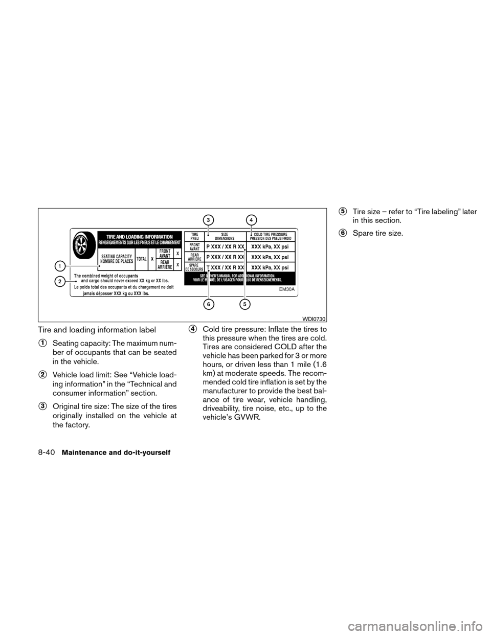
Tire and loading information label
�1Seating capacity: The maximum num-
ber of occupants that can be seated
in the vehicle.
�2Vehicle load limit: See “Vehicle load-
ing information” in the “Technical and
consumer information” section.
�3Original tire size: The size of the tires
originally installed on the vehicle at
the factory.
�4Cold tire pressure: Inflate the tires to
this pressure when the tires are cold.
Tires are considered COLD after the
vehicle has been parked for 3 or more
hours, or driven less than 1 mile (1.6
km) at moderate speeds. The recom-
mended cold tire inflation is set by the
manufacturer to provide the best bal-
ance of tire wear, vehicle handling,
driveability, tire noise, etc., up to the
vehicle’s GVWR.
�5Tire size – refer to “Tire labeling” later
in this section.
�6Spare tire size.
WDI0730
8-40Maintenance and do-it-yourself
Page 400 of 446
Checking tire pressure
1. Remove the valve stem cap from thetire.
2. Press the pressure gauge squarely onto the valve stem. Do not press too
hard or force the valve stem side-
ways, or air will escape. If the hissing
sound of air escaping from the tire is
heard while checking the pressure,
reposition the gauge to eliminate this
leakage. 3. Remove the gauge.
4. Read the tire pressure on the gauge
stem and compare to the specifica-
tion shown on the Tire and Loading
Information label.
5. Add air to the tire as needed. If too much air is added, press the core of
the valve stem briefly with the tip of
the gauge stem to release pressure.
Recheck the pressure and add or
release air as needed.
6. Install the valve stem cap.
7. Check the pressure of all other tires, including the spare.
LDI0393
Maintenance and do-it-yourself8-41
Trending: diagram, change key battery, rims, warning light, windshield wipers, maintenance schedule, differential

6. High-mount stoplight (if so equipped)
7. Trunk light
8. Spoiler mounted stoplight(if so e")