stop start NISSAN ALTIMA HYBRID 2007 L32A / 4.G Quick Reference Guide
[x] Cancel search | Manufacturer: NISSAN, Model Year: 2007, Model line: ALTIMA HYBRID, Model: NISSAN ALTIMA HYBRID 2007 L32A / 4.GPages: 28, PDF Size: 5.15 MB
Page 4 of 28

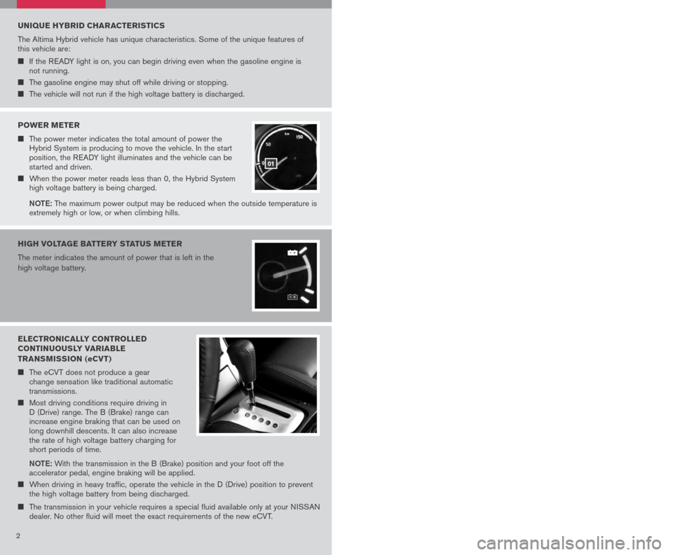
ELECTRONICALLY CONTROLLED
CONTINUOUSLY VARIABLE
TRANSMISSION (eCV T)
The eCVT does not produce a gear change sensation like traditional automatic transmissions.
Most driving conditions require driving in D (Drive) range. The B (Brake) range can increase engine braking that can be used on long downhill descents. It can also increase the rate of high voltage battery charging for short periods of time.
Note: With the transmission in the B (Brake) position and your foot off the accelerator pedal, engine braking will be applied.
When driving in heavy traffic, operate the vehicle in the D (Drive) position to prevent the high voltage battery from being discharged.
The transmission in your vehicle requires a special fluid available only at your NISSAN dealer. No other fluid will meet the exact requirements of the new eCVT.
32
UNIQUE HYBRID CHARACTERISTICS
The Altima Hybrid vehicle has unique characteristics. Some of the unique features of this vehicle are:
If the READY light is on, you can begin driving even when the gasoline engine is not running.
The gasoline engine may shut off while driving or stopping.
The vehicle will not run if the high voltage battery is discharged.
01
02
03
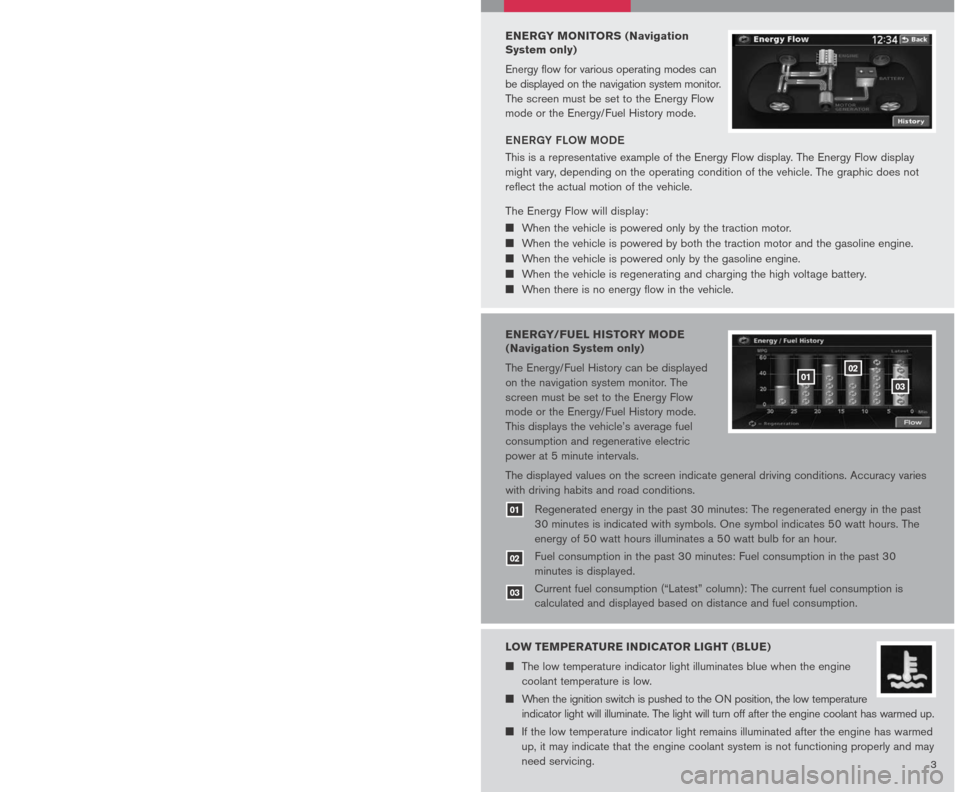
ENERGY/FUEL HISTORY MODE
(Navigation System only)
The Energy/Fuel History can be displayed
on the navigation system monitor. The
screen must be set to the Energy Flow
mode or the Energy/Fuel History mode.
This displays the vehicle’s average fuel
consumption and regenerative electric
power at 5 minute intervals.
The displayed values on the screen indicate general driving conditions. Accuracy varies
with driving habits and road conditions.
Regenerated energy in the past 30 minutes: The regenerated energy in the past
30 minutes is indicated with symbols. One symbol indicates 50 watt hours. The
energy of 50 watt hours illuminates a 50 watt bulb for an hour.
Fuel consumption in the past 30 minutes: Fuel consumption in the past 30
minutes is displayed.
Current fuel consumption (“Latest” column): The current fuel consumption is
calculated and displayed based on distance and fuel consumption.
0102
03
POWER METER
The power meter indicates the total amount of power the Hybrid System is producing to move the vehicle. In the start position, the READY light illuminates and the vehicle can be started and driven.
When the power meter reads less than 0, the Hybrid System high voltage battery is being charged.
Note: The maximum power output may be reduced when the outside temperature is extremely high or low, or when climbing hills.
01
HIGH VOLTAGE BATTERY STATUS METER
The meter indicates the amount of power that is left in the
high voltage battery.
LOW TEMPERATURE INDICATOR LIGHT (BLUE)
The low temperature indicator light illuminates blue when the engine
coolant temperature is low.
When the ignition switch is pushed to the ON position, the low temperature
indicator light will illuminate. The light will turn off after the engine coolant has warmed up.
If the low temperature indicator light remains illuminated after the engine has warmed
up, it may indicate that the engine coolant system is not functioning properly and may
need servicing.
ENERGY MONITORS (Navigation
System only)
Energy flow for various operating modes can
be displayed on the navigation system monitor.
The screen must be set to the Energy Flow
mode or the Energy/Fuel History mode.
eN eRGY FL oW M oDe
This is a representative example of the Energy Flow display. The Energy Flow display
might vary, depending on the operating condition of the vehicle. The graphic does not
reflect the actual motion of the vehicle.
The Energy Flow will display:
When the vehicle is powered only by the traction motor.
When the vehicle is powered by both the traction motor and the gasoline engine.
When the vehicle is powered only by the gasoline engine.
When the vehicle is regenerating and charging the high voltage battery.
When there is no energy flow in the vehicle.
Page 5 of 28

ELECTRONICALLY CONTROLLED
CONTINUOUSLY VARIABLE
TRANSMISSION (eCV T)
The eCVT does not produce a gear change sensation like traditional automatic transmissions.
Most driving conditions require driving in D (Drive) range. The B (Brake) range can increase engine braking that can be used on long downhill descents. It can also increase the rate of high voltage battery charging for short periods of time.
Note: With the transmission in the B (Brake) position and your foot off the accelerator pedal, engine braking will be applied.
When driving in heavy traffic, operate the vehicle in the D (Drive) position to prevent the high voltage battery from being discharged.
The transmission in your vehicle requires a special fluid available only at your NISSAN dealer. No other fluid will meet the exact requirements of the new eCVT.
32
UNIQUE HYBRID CHARACTERISTICS
The Altima Hybrid vehicle has unique characteristics. Some of the unique features of this vehicle are:
If the READY light is on, you can begin driving even when the gasoline engine is not running.
The gasoline engine may shut off while driving or stopping.
The vehicle will not run if the high voltage battery is discharged.
01
02
03
ENERGY/FUEL HISTORY MODE
(Navigation System only)
The Energy/Fuel History can be displayed
on the navigation system monitor. The
screen must be set to the Energy Flow
mode or the Energy/Fuel History mode.
This displays the vehicle’s average fuel
consumption and regenerative electric
power at 5 minute intervals.
The displayed values on the screen indicate general driving conditions. Accuracy varies
with driving habits and road conditions.
Regenerated energy in the past 30 minutes: The regenerated energy in the past
30 minutes is indicated with symbols. One symbol indicates 50 watt hours. The
energy of 50 watt hours illuminates a 50 watt bulb for an hour.
Fuel consumption in the past 30 minutes: Fuel consumption in the past 30
minutes is displayed.
Current fuel consumption (“Latest” column): The current fuel consumption is
calculated and displayed based on distance and fuel consumption.
0102
03
POWER METER
The power meter indicates the total amount of power the Hybrid System is producing to move the vehicle. In the start position, the READY light illuminates and the vehicle can be started and driven.
When the power meter reads less than 0, the Hybrid System high voltage battery is being charged.
Note: The maximum power output may be reduced when the outside temperature is extremely high or low, or when climbing hills.
01
HIGH VOLTAGE BATTERY STATUS METER
The meter indicates the amount of power that is left in the
high voltage battery.
LOW TEMPERATURE INDICATOR LIGHT (BLUE)
The low temperature indicator light illuminates blue when the engine
coolant temperature is low.
When the ignition switch is pushed to the ON position, the low temperature
indicator light will illuminate. The light will turn off after the engine coolant has warmed up.
If the low temperature indicator light remains illuminated after the engine has warmed
up, it may indicate that the engine coolant system is not functioning properly and may
need servicing.
ENERGY MONITORS (Navigation
System only)
Energy flow for various operating modes can
be displayed on the navigation system monitor.
The screen must be set to the Energy Flow
mode or the Energy/Fuel History mode.
eN eRGY FL oW M oDe
This is a representative example of the Energy Flow display. The Energy Flow display
might vary, depending on the operating condition of the vehicle. The graphic does not
reflect the actual motion of the vehicle.
The Energy Flow will display:
When the vehicle is powered only by the traction motor.
When the vehicle is powered by both the traction motor and the gasoline engine.
When the vehicle is powered only by the gasoline engine.
When the vehicle is regenerating and charging the high voltage battery.
When there is no energy flow in the vehicle.
Page 14 of 28

12 13
SEAT BELT WARNING LIGHT AND CHIME
The light and chime remind you to fasten your seat belts. The
light illuminates whenever the ignition key is turned to the ON
or START position and remains illuminated until the driver’s
seat belt is fastened. At the same time, the chime sounds for
approximately 6 seconds unless the driver’s seat belt is securely
fastened.
The seat belt warning light may also illuminate if the front passenger’s seat belt is
not fastened when the front passenger’s seat is occupied. For 7 seconds after the
ignition switch is in the ON position, the system does not activate the warning light
for the front passenger.
Refer to the Owner’s Manual for detailed information regarding seat belt usage.
CHILD SAFETY REAR DOOR LOCK
Child safety locks help prevent the rear doors from being
opened accidentally, especially when small children are
in the vehicle. The child safety lock levers are located on
the edge of the rear doors. When the lever is in the LOCK
position, the door can be opened only from the outside.
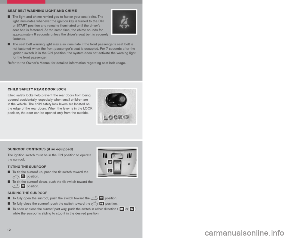
SUNROOF CONTROLS (if so equipped)
The ignition switch must be in the ON position to operate
the sunroof.
TILTING THE SUNROOF
To tilt the sunroof up, push the tilt switch toward the
01 position.
To tilt the sunroof down, push the tilt switch toward the
02 position.
SLIDING THE SUNROOF
To fully open the sunroof, push the switch toward the 02 position.
To fully close the sunroof, push the switch toward the 01 position.
To open or close the sunroof part way, push the switch in either direction ( 01 or 02 )
while the sunroof is sliding to stop it in the desired position.
02
01
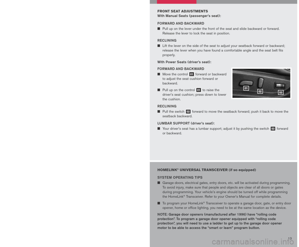
FRONT SEAT ADJUSTMENTS
With Manual Seats (passenger’s seat):
F ORW aRD a ND back WaRD
Pull up on the lever under the front of the seat and slide backward or forward.
Release the lever to lock the seat in position.
R Ec LINING
Lift the lever on the side of the seat to adjust your seatback forward or backward;
release the lever when you have found a comfortable angle and the seat belt fits
properly.
With power Seats (driver’s seat):
F ORW aRD a ND back WaRD
Move the control 01 forward or backward
to adjust the seat cushion forward or
backward.
Pull up on the control 01 to raise the
driver’s seat cushion; press down to lower
the cushion.
R Ec LINING
Pull the switch 02 forward to move the seatback forward; push it back to move the
seatback backward.
L UM baR S Upp ORT
(driver’s seat):
Your driver’s seat has a lumbar support; adjust it by pushing the switch 03 forward
or backward.
010203
HOMELINK® UNIVERSAL TRANSCEIVER (if so equipped)
SYSTEM O pER aTING TI pS
Garage doors, electrical gates, entry doors, etc. will be activated during programming.
To avoid injury, make sure that people and objects are clear of all doors or gates
during programming. Your vehicle’s engine should be turned off while programming
the HomeLink® Transceiver. Refer to your Owner’s Manual for complete details.
To program your HomeLink® Transceiver to operate a garage door, gate, or entry door
opener, home or office lighting, you need to be at the same location as the device.
NOTE: Garage door openers (manufactured after 1996) have “rolling code
protection”. To program a garage door opener equipped with “rolling code
protection”, you will need to use a ladder to get up to the garage door opener
motor to be able to access the “smart or learn” program button.
Page 15 of 28

12 13
SEAT BELT WARNING LIGHT AND CHIME
The light and chime remind you to fasten your seat belts. The
light illuminates whenever the ignition key is turned to the ON
or START position and remains illuminated until the driver’s
seat belt is fastened. At the same time, the chime sounds for
approximately 6 seconds unless the driver’s seat belt is securely
fastened.
The seat belt warning light may also illuminate if the front passenger’s seat belt is
not fastened when the front passenger’s seat is occupied. For 7 seconds after the
ignition switch is in the ON position, the system does not activate the warning light
for the front passenger.
Refer to the Owner’s Manual for detailed information regarding seat belt usage.
CHILD SAFETY REAR DOOR LOCK
Child safety locks help prevent the rear doors from being
opened accidentally, especially when small children are
in the vehicle. The child safety lock levers are located on
the edge of the rear doors. When the lever is in the LOCK
position, the door can be opened only from the outside.
SUNROOF CONTROLS (if so equipped)
The ignition switch must be in the ON position to operate
the sunroof.
TILTING THE SUNROOF
To tilt the sunroof up, push the tilt switch toward the
01 position.
To tilt the sunroof down, push the tilt switch toward the
02 position.
SLIDING THE SUNROOF
To fully open the sunroof, push the switch toward the 02 position.
To fully close the sunroof, push the switch toward the 01 position.
To open or close the sunroof part way, push the switch in either direction ( 01 or 02 )
while the sunroof is sliding to stop it in the desired position.
02
01
FRONT SEAT ADJUSTMENTS
With Manual Seats (passenger’s seat):
F ORW aRD a ND back WaRD
Pull up on the lever under the front of the seat and slide backward or forward.
Release the lever to lock the seat in position.
R Ec LINING
Lift the lever on the side of the seat to adjust your seatback forward or backward;
release the lever when you have found a comfortable angle and the seat belt fits
properly.
With power Seats (driver’s seat):
F ORW aRD a ND back WaRD
Move the control 01 forward or backward
to adjust the seat cushion forward or
backward.
Pull up on the control 01 to raise the
driver’s seat cushion; press down to lower
the cushion.
R Ec LINING
Pull the switch 02 forward to move the seatback forward; push it back to move the
seatback backward.
L UM baR S Upp ORT
(driver’s seat):
Your driver’s seat has a lumbar support; adjust it by pushing the switch 03 forward
or backward.
010203
HOMELINK® UNIVERSAL TRANSCEIVER (if so equipped)
SYSTEM O pER aTING TI pS
Garage doors, electrical gates, entry doors, etc. will be activated during programming.
To avoid injury, make sure that people and objects are clear of all doors or gates
during programming. Your vehicle’s engine should be turned off while programming
the HomeLink® Transceiver. Refer to your Owner’s Manual for complete details.
To program your HomeLink® Transceiver to operate a garage door, gate, or entry door
opener, home or office lighting, you need to be at the same location as the device.
NOTE: Garage door openers (manufactured after 1996) have “rolling code
protection”. To program a garage door opener equipped with “rolling code
protection”, you will need to use a ladder to get up to the garage door opener
motor to be able to access the “smart or learn” program button.