brakes NISSAN ALTIMA SV 2018 Owners Manual
[x] Cancel search | Manufacturer: NISSAN, Model Year: 2018, Model line: ALTIMA SV, Model: NISSAN ALTIMA SV 2018Pages: 467, PDF Size: 5.06 MB
Page 307 of 467
∙ The system may not detect the ve-hicle in front of you in certain road or
weather conditions. To avoid acci-
dents, never use the ICC system under
the following conditions:
– On roads where the traffic is heavy or there are sharp curves
– On slippery road surfaces such as on ice or snow, etc.
– During bad weather (rain, fog, snow, etc.)
– When rain, snow or dirt adhere to the bumper around the distance
sensor
– On steep downhill roads (the ve- hicle may go beyond the set ve-
hicle speed and frequent braking
may result in overheating the
brakes)
– On repeated uphill and downhill roads
– When traffic conditions make it dif- ficult to keep a proper distance be-
tween vehicles because of fre-
quent acceleration or deceleration – Interference by other radar
sources.
∙ Do not use the ICC system if you are towing a trailer. The system may not
detect a vehicle ahead.
∙ In some road or traffic conditions, a vehicle or object can unexpectedly
come into the sensor detection zone
and cause automatic braking. Always
stay alert and avoid using the ICC sys-
tem where not recommended in this
warning section.
The radar sensor will not detect the follow-
ing objects: ∙ Stationary and slow moving vehicles
∙ Pedestrians or objects in the roadway
∙ Oncoming vehicles in the same lane
∙ Motorcycles traveling offset in the travel lane
The following are some conditions in which
the sensor cannot properly detect a ve-
hicle ahead and the system may not oper-
ate properly: ∙ When snow or road spray from traveling vehicles reduces the sensor’s detection. ∙ When excessively heavy baggage is
loaded in the rear seat or the trunk of
your vehicle.
The ICC system is designed to automati-
cally check the sensor’s operation within
the limitations of the system.
The detection zone of the ICC sensor is
limited. A vehicle ahead must be in the de-
tection zone for the vehicle-to-vehicle dis-
tance detection mode to maintain the se-
lected distance from the vehicle ahead.
A vehicle ahead may move outside of the
detection zone due to its position within
the same lane of travel. Motorcycles may
not be detected in the same lane ahead if
they are traveling offset from the centerline
of the lane. A vehicle that is entering the
lane ahead may not be detected until the
vehicle has completely moved into the
lane.
If this occurs, the ICC system may warn
you by blinking the system indicator and
sounding the chime. The driver may
have to manually control the proper dis-
tance away from the vehicle traveling
ahead.
Starting and driving5-53
Page 335 of 467
The brake system has two separate hy-
draulic circuits. If one circuit malfunctions,
you will still have braking at two wheels.
BRAKE PRECAUTIONS
Vacuum assisted brakes
The brake booster aids braking by using
engine vacuum. If the engine stops, you
can stop the vehicle by depressing the
brake pedal. However, greater foot pres-
sure on the brake pedal will be required to
stop the vehicle and stopping distance will
be longer.
Using the brakes
Avoid resting your foot on the brake pedal
while driving. This will overheat the brakes,
wear out the brake pads faster, and reduce
gas mileage.
To help reduce brake wear and to prevent
the brakes from overheating, reduce speed
and downshif t to a lower gear before going
down a slope or long grade. Overheated
brakes may reduce braking performance
and could result in loss of vehicle control.
Page 336 of 467
– When replacing tires, install thespecified size of tires on all four
wheels.
– When installing a spare tire, make sure that it is the proper size and
type as specified on the Tire and
Loading Information label. For ad-
ditional information, refer to “Tire
and Loading Information label” in
the “Technical and consumer infor-
mation” section of this manual.
– For additional information, refer to “Wheels and tires” in the “Do-it-
yourself ” section of this manual.
The ABS controls the brakes so the wheels
do not lock during hard braking or when
braking on slippery surfaces. The system
detects the rotation speed at each wheel
and varies the brake fluid pressure to pre-
vent each wheel from locking and sliding.
By preventing each wheel from locking, the
system helps the driver maintain steering
control and helps to minimize swerving
and spinning on slippery surfaces.
Using the system
Depress the brake pedal and hold it down.
Depress the brake pedal with firm steady
pressure, but do not pump the brakes. The Anti-lock Braking System will operate to
prevent the wheels from locking up. Steer
the vehicle to avoid obstacles.
Page 340 of 467
WARNING
∙ Never rely solely on the hill start assistsystem to prevent the vehicle from
moving backward on a hill. Always
drive carefully and attentively. De-
press the brake pedal when the ve-
hicle is stopped on a steep hill. Be es-
pecially careful when stopped on a hill
on frozen or muddy roads. Failure to
prevent the vehicle from rolling back-
wards may result in a loss of control of
the vehicle and possible serious injury
or death.
∙ The hill start assist system is not de- signed to hold the vehicle at a stand-
still on a hill. Depress the brake pedal
when the vehicle is stopped on a
steep hill. Failure to do so may cause
the vehicle to roll backwards and may
result in a collision or serious personal
injury.
∙ The hill start assist system may not prevent the vehicle from rolling back-
wards on a hill under all load or road
conditions. Always be prepared to de-
press the brake pedal to prevent the
vehicle from rolling backwards. Fail-
ure to do so may result in a collision or
serious personal injury. When the vehicle is stopped on a hill, the hill
start assist system automatically keeps
the brakes applied to help prevent the ve-
hicle from rolling backward in the time it
takes the driver to release the brake pedal
and apply the accelerator.
The hill start assist system will operate au-
tomatically under the following conditions:
∙ The transmission is shif ted to a forward or reverse gear.
∙ The vehicle is stopped completely on a hill by applying the brake. The maxi-
mum holding time is 2 seconds. Af ter
2 seconds the vehicle will begin to roll
back and the hill start assist system will
stop operating completely.
The hill start assist system will not operate
when the shif t lever is placed in the N (Neu-
tral) or P (Park) position or on a flat and level
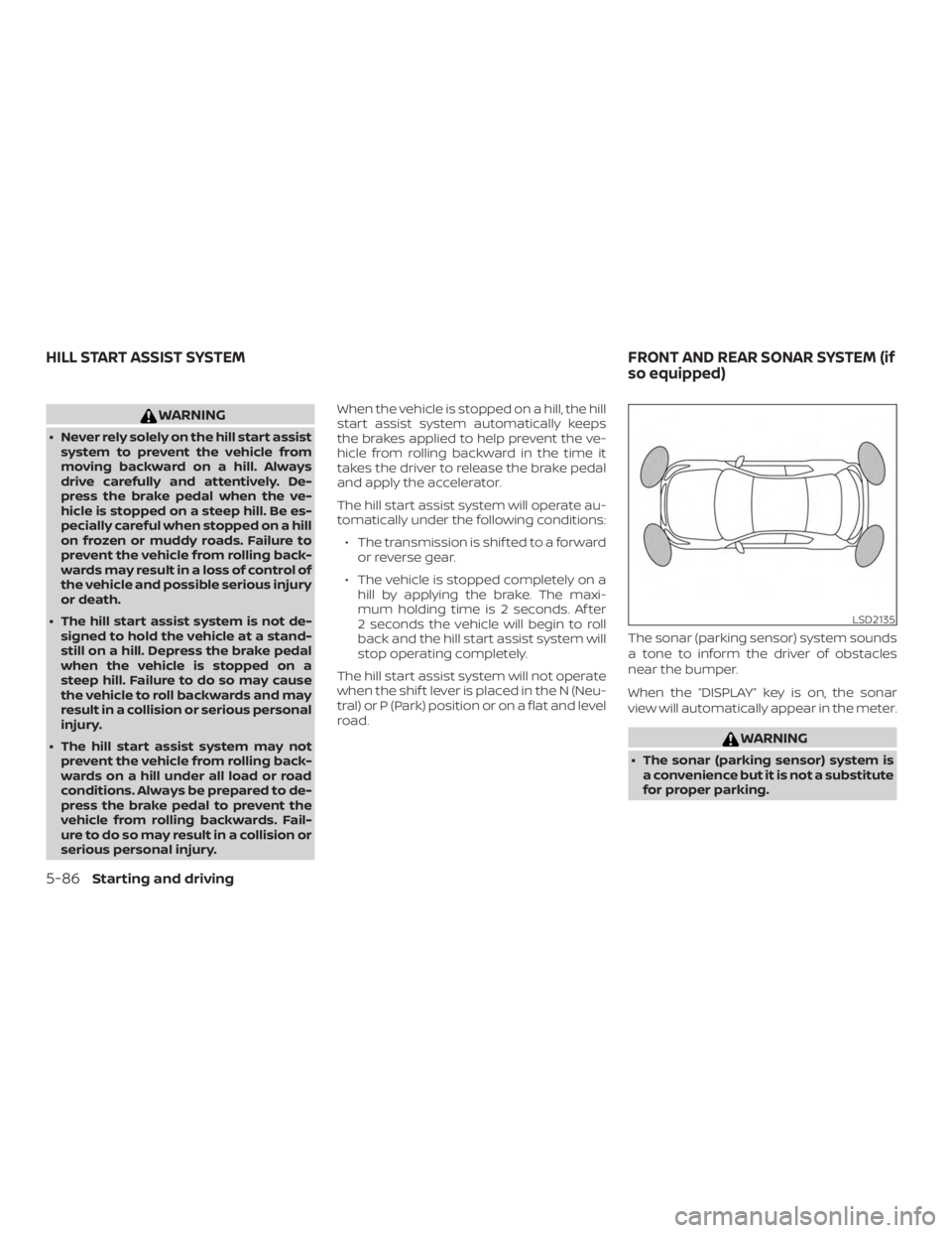
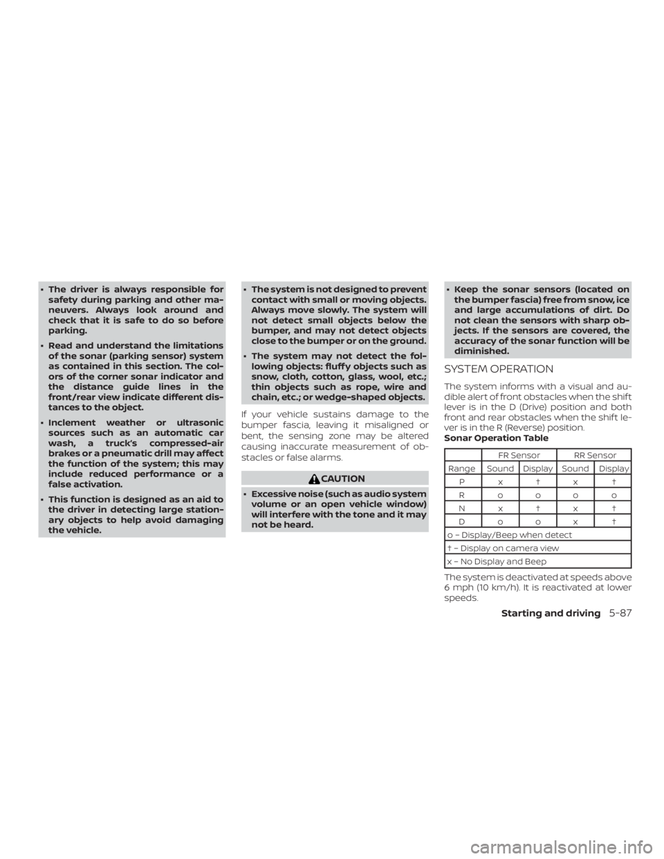
road. The sonar (parking sensor) system sounds
a tone to inform the driver of obstacles
near the bumper.
When the “DISPLAY” key is on, the sonar
view will automatically appear in the meter.
Page 341 of 467
∙ The driver is always responsible forsafety during parking and other ma-
neuvers. Always look around and
check that it is safe to do so before
parking.
∙ Read and understand the limitations of the sonar (parking sensor) system
as contained in this section. The col-
ors of the corner sonar indicator and
the distance guide lines in the
front/rear view indicate different dis-
tances to the object.
∙ Inclement weather or ultrasonic sources such as an automatic car
wash, a truck’s compressed-air
brakes or a pneumatic drill may affect
the function of the system; this may
include reduced performance or a
false activation.
∙ This function is designed as an aid to the driver in detecting large station-
ary objects to help avoid damaging
the vehicle. ∙ The system is not designed to prevent
contact with small or moving objects.
Always move slowly. The system will
not detect small objects below the
bumper, and may not detect objects
close to the bumper or on the ground.
∙ The system may not detect the fol- lowing objects: fluff y objects such as
snow, cloth, cotton, glass, wool, etc.;
thin objects such as rope, wire and
chain, etc.; or wedge-shaped objects.
If your vehicle sustains damage to the
bumper fascia, leaving it misaligned or
bent, the sensing zone may be altered
causing inaccurate measurement of ob-
stacles or false alarms.
Page 344 of 467
∙ Read and understand the limitationsof the sonar system as contained in
this section. Inclement weather may
affect the function of the sonar sys-
tem; this may include reduced perfor-
mance or a false activation.
∙ The system is deactivated at speeds above 6 mph (10 km/h). It is reacti-
vated at lower speeds.
∙ Inclement weather or ultrasonic sources such as an automatic car
wash, a truck’s compressed-air
brakes or a pneumatic drill may affect
the function of the system; this may
include reduced performance or a
false activation.
∙ The system is not designed to prevent contact with small or moving objects.
Always move slowly. The system will
not detect small objects below the
bumper or on the ground.
∙ The system may not detect the fol- lowing objects: fluff y objects such as
snow, cloth, cotton, glass-wool, etc.;
thin objects such as rope, wire and
chain, etc.; or wedge-shaped objects. ∙ The system may not detect objects at
speeds above 3 mph (5 km/h) and
may not detect certain angular or
moving objects.
SYSTEM TEMPORARILY
UNAVAILABLE
When sonar blockage is detected, the sys-
tem will be deactivated automatically.
The system is not available until the condi-
tions no longer exist.
The sonar sensors may be blocked by tem-
porary ambient conditions such as splash-
ing water, mist or fog. The blocked condi-
tion may also be caused by objects such as
ice, frost or dirt obstructing the sonar sen-
sors.
Action to take:
When the above conditions no longer exist,
the system will resume automatically.
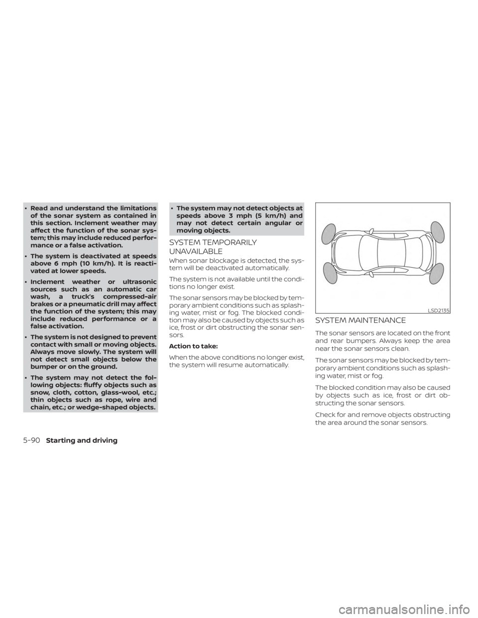
SYSTEM MAINTENANCE
The sonar sensors are located on the front
and rear bumpers. Always keep the area
near the sonar sensors clean.
The sonar sensors may be blocked by tem-
porary ambient conditions such as splash-
ing water, mist or fog.
The blocked condition may also be caused
by objects such as ice, frost or dirt ob-
structing the sonar sensors.
Check for and remove objects obstructing
the area around the sonar sensors.
Page 393 of 467
If the brakes do not operate properly, have
the brakes checked. It is recommended
that you visit a NISSAN dealer for this ser-
vice.
Self-adjusting brakes
Your vehicle is equipped with self-adjusting
brakes.
The front and rear disc-type brakes self-
adjust every time the brake pedal is ap-
plied.
Page 460 of 467
Armrests ...................1-7
Frontseats..................1-2
Manual front seat adjustment ......1-3
Rearseat.................. .1-6
Security indicator light ............2-17
Security system (NISSAN Vehicle Immobilizer
System), engine start ..........2-32,5-12
Security systems Vehicle security system ..........2-31
Self-adjustingbrakes.............8-21
Service manual order form .........10-21
Servicing air conditioner ...........4-24
Shif ting Continuously Variable Transmission
(CVT) .....................5-16
Shiftleverlockrelease............5-19
Shoulder belt height adjustment ......1-19
Siri® Eyes-Free .................4-50
Spark plug replacement ...........8-17
Spark plugs ...................8-17
Specifications .................10-8
Speedometer ..................2-4
Speedometer and odometer ........2-4
Spotlights(Seemaplight)..........2-55
SRS warning label ...............1-61
Stability control ................5-83
Standard maintenance ............9-7
Starting Before starting the engine ........5-12
Jumpstarting............6-10,8-15
Precautions when starting and
driving .....................5-2
Push starting ................6-12
Starting the engine ............5-13
Starting the engine ..............5-13 Steering
Powersteeringfluid............8-11
Powersteeringsystem .........5-80
Steering wheel .................3-28
Stoplight....................8-28
Storage.....................2-45
Sunglasses case ................2-47
Sunglasses holder ...............2-47
Sunroof (see Moonroof ) ...........2-52
Sunvisors....................3-29
Supplemental air bag warning
light.................... .1-62, 2-15
Supplemental front impact air bag
system ..................... .1-51
Supplemental restraint system Information and warning labels .....1-61
Precautions on supplemental restraint
system ................... .1-44
Supplemental restraint system
(Supplemental air bag system) .......1-44
Switch Autolightswitch..............2-36
Automatic power window switch . . .2-51
Foglightswitch..............2-40
Hazard warning flasher switch ......6-2
Headlight and turn signal switch ....2-35
Headlightcontrolswitch.........2-35
Instrument brightness control .....2-39
Power door lock switch ........3-5,3-6
Rear window and outside mirror
defrosterswitch..............2-35
Turn signal switch .............2-39 T
Tachometer ...................2-5
Temperature gauge Engine coolant temperature gauge . .2-5
Thef t (NISSAN Vehicle Immobilizer System),
engine start ...............2-32,5-12
Three-waycatalyst...............5-2
Tilt Telescopicsteering............3-29
Tire F
lattire..................6-3,6-4
Spare tire ................6-5,8-43
Tire and Loading Information label . .10-12
Tire chains .................8-39
Tire pressure ................8-31
Tirerotation ................8-40
Types of tires ................8-38
Uniform tire quality grading .......10-17
Wheels and tires ..............8-31
Wheel/tire size ...............10-9
Tire pressure Low tire pressure warning light .....2-12
Tire Pressure Monitoring System
(TPMS)....................5-3,6-3
Towing 4-wheel drive models ...........6-14
Flattowing.................10-17
Trailertowing ...............10-17
Towingatrailer................10-17
Towingyourvehicle..............6-13
Transceiver HomeLink® Universal
Transceiver ..........2-56,2-58,2-59
11-6