oil pressure NISSAN ARMADA 2019 Owner´s Manual
[x] Cancel search | Manufacturer: NISSAN, Model Year: 2019, Model line: ARMADA, Model: NISSAN ARMADA 2019Pages: 536, PDF Size: 2.56 MB
Page 17 of 536
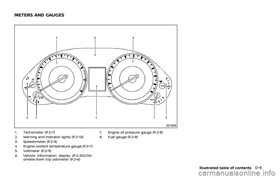
SIC4368
1. Tachometer (P.2-7)
2. Warning and indicator lights (P.2-10)
3. Speedometer (P.2-6)
4. Engine coolant temperature gauge (P.2-7)
5. Voltmeter (P.2-9)
6. Vehicle information display (P.2-20)/Od-ometer/twin trip odometer (P.2-6) 7. Engine oil pressure gauge (P.2-8)
8. Fuel gauge (P.2-8)
Illustrated table of contents0-9
METERS AND GAUGES
Page 19 of 536
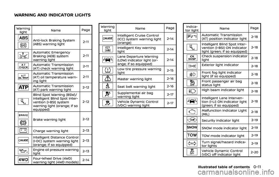
Warninglight Name
Page
Anti-lock Braking System
(ABS) warning light 2-11
Automatic Emergency
Braking (AEB) system
warning light2-11
Automatic Transmission
(AT) check warning light
2-11
Automatic Transmission
(AT) oil temperature warn-
ing light2-11
Automatic Transmission
(AT) park warning light
2-12
Blind Spot Warning (BSW)/
Intelligent Blind Spot Inter-
vention (I-BSI) system
warning light (orange; if so
equipped)2-12
Brake warning light
2-12
Charge warning light2-13
Intelligent Distance Control
(I-DC) system warning light
(orange; if so equipped)2-13
Engine oil pressure warning
light
2-13
Four-Wheel Drive (4WD)
warning light (4WD models)2-14Warning
light Name
Page
Intelligent Cruise Control
(ICC) system warning light
(orange) 2-14
Intelligent Key warning
light
2-14
Lane Departure Warning
(LDW) indicator light (or-
ange; if so equipped)2-14
Low tire pressure warning
light
2-15
Master warning light
2-16
Seat belt warning light2-16
Supplemental air bag
warning light 2-17
Vehicle Dynamic Control
(VDC) warning light2-17Indica-
tor light Name
Page
Automatic Transmission
(AT) position indicator light 2-18
Intelligent Blind Spot Inter-
vention (I-BSI) ON indicator
light (green; if so equipped)2-18
Check suspension indicator
light
2-18
Exterior light indicator
2-18
Front fog light indicator
light (if so equipped)2-18
Front passenger air bag
status light2-18
High beam indicator light
2-18
Intelligent Lane Interven-
tion (I-LI) ON indicator light
(green; if so equipped)2-18
Malfunction Indicator Light
(MIL)
2-18
Security indicator light
2-19
SNOW mode indicator light2-19
TOW mode indicator light2-19
Turn signal/hazard indica-
tor lights2-19
Vehicle Dynamic Control
(VDC) off indicator light2-20
Illustrated table of contents0-11
WARNING AND INDICATOR LIGHTS
Page 95 of 536
2 Instruments and controls
Cockpit ........................................................................\
.......................... 2-3
Instrument panel ........................................................................\
.. 2-4
Meters and gauges ..................................................................... 2-5Speedometer and odometer ........................................ 2-6
Tachometer ........................................................................\
........ 2-7
Engine coolant temperature gauge ....................... 2-7
Fuel gauge ........................................................................\
........... 2-8
Engine oil pressure gauge .............................................. 2-8
Voltmeter ........................................................................\
.............. 2-9
Meter/ring illumination and needle sweep ....... 2-9
Warning lights, indicator lights and
audible reminders ..................................................................... 2-10 Checking lights ..................................................................... 2-11
Warning lights ........................................................................\
2-11
Indicator lights ...................................................................... 2-17
Audible reminders .............................................................. 2-20
Vehicle information display ............................................... 2-20 Operational indicators .................................................... 2-23
Maintenance indicators ................................................. 2-26
Trip computer ........................................................................\
2-28
Security systems ........................................................................\
2-30 Vehicle Security System ................................................ 2-30
NISSAN Vehicle Immobilizer System .................... 2-32 Wiper and washer switch ................................................... 2-33
Windshield wiper and washer operation ...... 2-34
Rain-sensing auto wiper system (if
so equipped) ........................................................................\
. 2-34
Rear window wiper and
washer operation ............................................................. 2-36
Rear window and outside mirror
(if so equipped) defroster switch ................................. 2-36
Windshield deicer switch (if so equipped) ............. 2-36
Headlight and turn signal switch ................................ 2-37 Headlight switch ............................................................... 2-37
Instrument brightness control .............................. 2-41
Turn signal switch ........................................................... 2-41
Fog light switch (if so equipped) ......................... 2-42
Heated steering wheel (if so equipped) .................. 2-42
Horn ........................................................................\
............................. 2-43
Heated seats ........................................................................\
......... 2-43 Front (if so equipped) .................................................... 2-44
Rear (if so equipped) ...................................................... 2-45
Climate controlled seats (if so equipped) ............. 2-45
Warning systems switch (if so equipped) ............. 2-46
SNOW mode switch ................................................................ 2-47
TOW mode switch .................................................................... 2-47
Vehicle Dynamic Control (VDC) OFF switch ........ 2-48
Page 99 of 536
SIC4368
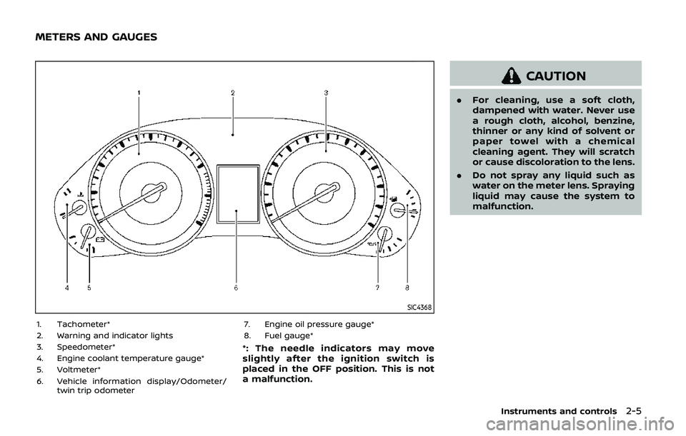
1. Tachometer*
2. Warning and indicator lights
3. Speedometer*
4. Engine coolant temperature gauge*
5. Voltmeter*
6. Vehicle information display/Odometer/twin trip odometer 7. Engine oil pressure gauge*
8. Fuel gauge*
*: The needle indicators may move
slightly after the ignition switch is
placed in the OFF position. This is not
a malfunction.
CAUTION
.
For cleaning, use a soft cloth,
dampened with water. Never use
a rough cloth, alcohol, benzine,
thinner or any kind of solvent or
paper towel with a chemical
cleaning agent. They will scratch
or cause discoloration to the lens.
. Do not spray any liquid such as
water on the meter lens. Spraying
liquid may cause the system to
malfunction.
Instruments and controls2-5
METERS AND GAUGES
Page 102 of 536
2-8Instruments and controls
SIC4374
FUEL GAUGE
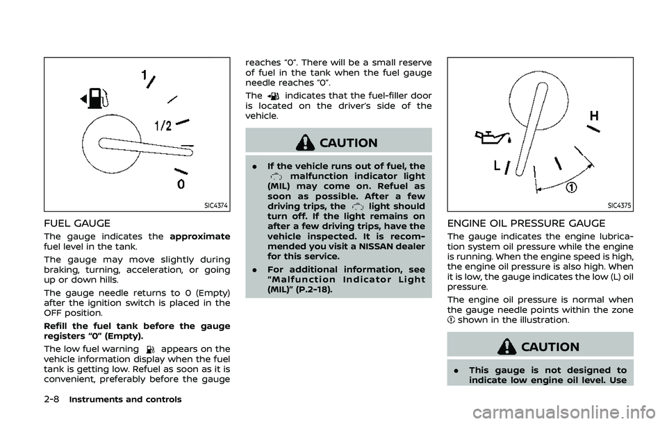
The gauge indicates theapproximate
fuel level in the tank.
The gauge may move slightly during
braking, turning, acceleration, or going
up or down hills.
The gauge needle returns to 0 (Empty)
after the ignition switch is placed in the
OFF position.
Refill the fuel tank before the gauge
registers “0” (Empty).
The low fuel warning
appears on the
vehicle information display when the fuel
tank is getting low. Refuel as soon as it is
convenient, preferably before the gauge reaches “0”. There will be a small reserve
of fuel in the tank when the fuel gauge
needle reaches “0”.
The
indicates that the fuel-filler door
is located on the driver’s side of the
vehicle.
CAUTION
. If the vehicle runs out of fuel, themalfunction indicator light
(MIL) may come on. Refuel as
soon as possible. After a few
driving trips, the
light should
turn off. If the light remains on
after a few driving trips, have the
vehicle inspected. It is recom-
mended you visit a NISSAN dealer
for this service.
. For additional information, see
“Malfunction Indicator Light
(MIL)” (P.2-18).SIC4375
ENGINE OIL PRESSURE GAUGE
The gauge indicates the engine lubrica-
tion system oil pressure while the engine
is running. When the engine speed is high,
the engine oil pressure is also high. When
it is low, the gauge indicates the low (L) oil
pressure.
The engine oil pressure is normal when
the gauge needle points within the zone
shown in the illustration.
CAUTION
.This gauge is not designed to
indicate low engine oil level. Use
Page 104 of 536
2-10Instruments and controls
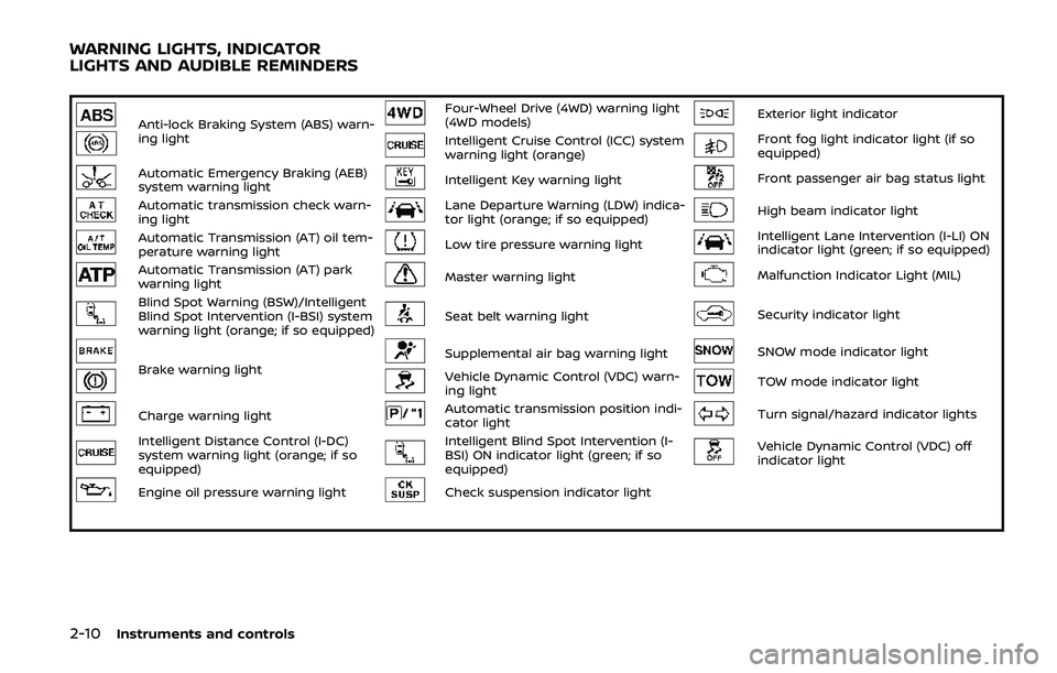
Anti-lock Braking System (ABS) warn-
ing lightFour-Wheel Drive (4WD) warning light
(4WD models)Exterior light indicator
Intelligent Cruise Control (ICC) system
warning light (orange)Front fog light indicator light (if so
equipped)
Automatic Emergency Braking (AEB)
system warning lightIntelligent Key warning lightFront passenger air bag status light
Automatic transmission check warn-
ing lightLane Departure Warning (LDW) indica-
tor light (orange; if so equipped)High beam indicator light
Automatic Transmission (AT) oil tem-
perature warning lightLow tire pressure warning lightIntelligent Lane Intervention (I-LI) ON
indicator light (green; if so equipped)
Automatic Transmission (AT) park
warning lightMaster warning lightMalfunction Indicator Light (MIL)
Blind Spot Warning (BSW)/Intelligent
Blind Spot Intervention (I-BSI) system
warning light (orange; if so equipped)Seat belt warning lightSecurity indicator light
Brake warning lightSupplemental air bag warning lightSNOW mode indicator light
Vehicle Dynamic Control (VDC) warn-
ing lightTOW mode indicator light
Charge warning lightAutomatic transmission position indi-
cator lightTurn signal/hazard indicator lights
Intelligent Distance Control (I-DC)
system warning light (orange; if so
equipped)Intelligent Blind Spot Intervention (I-
BSI) ON indicator light (green; if so
equipped)Vehicle Dynamic Control (VDC) off
indicator light
Engine oil pressure warning lightCheck suspension indicator light
WARNING LIGHTS, INDICATOR
LIGHTS AND AUDIBLE REMINDERS
Page 107 of 536
WARNING
.Your brake system may not be
working properly if the warning
light is on. Driving could be dan-
gerous. If you judge it to be safe,
drive carefully to the nearest
service station for repairs. Other-
wise, have your vehicle towed
because driving it could be dan-
gerous.
. Pressing the brake pedal with the
engine stopped and/or low brake
fluid level may increase your
stopping distance and braking
will require greater pedal effort
as well as pedal travel.
. If the brake fluid level is below the
minimum or MIN mark on the
brake fluid reservoir, do not drive
until the brake system has been
checked. It is recommended you
visit a NISSAN dealer for this
service.
Charge warning light
If the light comes on while the engine is
running, it may indicate the charging
system is not functioning properly. Turn
the engine off and check the alternator
belt. If the belt is loose, broken, missing or
if the light remains on, have your vehicle
serviced immediately. It is recommended
you visit a NISSAN dealer for this service.
CAUTION
Do not continue driving if the alter-
nator belt is loose, broken or miss-
ing.
Intelligent Distance Control (I-
DC) system warning light (orange; if
so equipped)
This light comes on if there is a malfunc-
tion in the Intelligent Distance Control (I-
DC) system.
If the warning light illuminates, park the
vehicle in a safe place. Turn the engine off,
restart the engine, resume driving and
turn on the I-DC system again.
If it is not possible to turn on the system
or the warning light stays on, it may indicate that the system is malfunction-
ing. Although the vehicle is still drive-
able under normal conditions, have the
vehicle checked. It is recommended you
visit a NISSAN dealer for this service.
See “Intelligent Distance Control (I-DC)”
(P.5-89).
Engine oil pressure warning
light
This light warns of low engine oil pres-
sure. If the light flickers or comes on
during normal driving, pull off the road in
a safe area, stop the engine immediately
and call a NISSAN dealer or other author-
ized repair shop.
The engine oil pressure warning light is
not designed to indicate a low oil level.
Use the dipstick to check the oil level.
(See “Engine oil” (P.8-6).)
CAUTION
Running the engine with the engine
oil pressure warning light on could
cause serious damage to the engine
almost immediately. Such damage is
not covered by warranty. Turn off the
engine as soon as it is safe to do so.
Instruments and controls2-13
Page 120 of 536
2-26Instruments and controls
26. Check back seat for all articles
When the rear door alert system is
enabled, this message appears when the
vehicle comes to a complete stop, the
shift lever is moved from the D (Drive) or R
(Reverse) position to P (Park) position, and
the driver exits the vehicle. This message
alerts the driver, after a period of time, to
check for items in the rear seat after the
audible alert has been provided.
NOTE:
This rear door alert system is disabled
until a driver enables it using the rear
door alert switch.
For more details, see “Rear door alert”
(P.2-49).
SIC4325
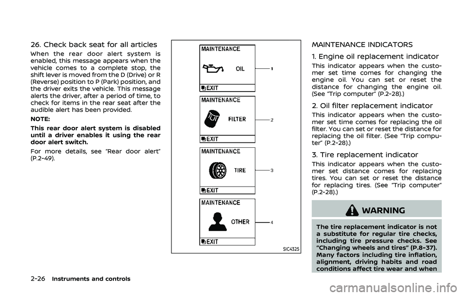
MAINTENANCE INDICATORS
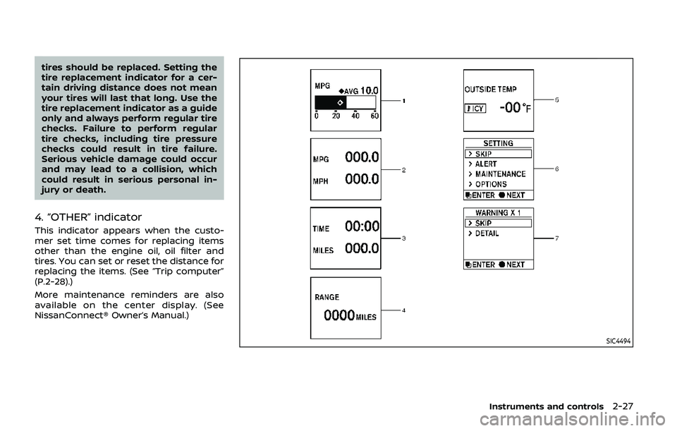
1. Engine oil replacement indicator
This indicator appears when the custo-
mer set time comes for changing the
engine oil. You can set or reset the
distance for changing the engine oil.
(See “Trip computer” (P.2-28).)
2. Oil filter replacement indicator
This indicator appears when the custo-
mer set time comes for replacing the oil
filter. You can set or reset the distance for
replacing the oil filter. (See “Trip compu-
ter” (P.2-28).)
3. Tire replacement indicator
This indicator appears when the custo-
mer set distance comes for replacing
tires. You can set or reset the distance
for replacing tires. (See “Trip computer”
(P.2-28).)
WARNING
The tire replacement indicator is not
a substitute for regular tire checks,
including tire pressure checks. See
“Changing wheels and tires” (P.8-37).
Many factors including tire inflation,
alignment, driving habits and road
conditions affect tire wear and when
Page 121 of 536
tires should be replaced. Setting the
tire replacement indicator for a cer-
tain driving distance does not mean
your tires will last that long. Use the
tire replacement indicator as a guide
only and always perform regular tire
checks. Failure to perform regular
tire checks, including tire pressure
checks could result in tire failure.
Serious vehicle damage could occur
and may lead to a collision, which
could result in serious personal in-
jury or death.
4. “OTHER” indicator
This indicator appears when the custo-
mer set time comes for replacing items
other than the engine oil, oil filter and
tires. You can set or reset the distance for
replacing the items. (See “Trip computer”
(P.2-28).)
More maintenance reminders are also
available on the center display. (See
NissanConnect® Owner’s Manual.)
SIC4494
Instruments and controls2-27
Page 278 of 536
5-18Starting and driving
If:
1. The engine coolant temperature is notreduced.
2. The air conditioning cooling function does not turn back ON.
3. The engine oil pressure warning light
illuminates or engine coolant
temperature gauge does not return
to the normal range from the H
position, this may indicate a malfunc-
tion. Move the vehicle off the road to a
safe area and allow the engine to cool.
If after checking the oil and coolant,
the
remains on or engine coolant
temperature does not return to the
normal range, do not continue to
drive. It is recommended you contact
a NISSAN dealer.
The Malfunction Indicator Light (MIL)
may also come ON. You do not need to
have your vehicle towed, unless it re-
mains on, but have it inspected soon. It is
recommended you contact a NISSAN
dealer for this service. See “Warning lights,
indicator lights and audible reminders”
(P.2-10).
WARNING
Overheating can result in reduced
engine power and vehicle speed.
The reduced speed may be lower
than other traffic, which could in-
crease the chance of a collision. Be
especially careful when driving. If the
vehicle cannot maintain a safe driv-
ing speed, pull to the side of the road
in a safe area. Allow the engine to
cool and return to normal operation.
See “If your vehicle overheats” (P.6-
14).
CAUTION
Running the engine with the engine
oil pressure warning light on could
cause serious damage to the engine
almost immediately. Such damage is
not covered by warranty. Turn off the
engine as soon as it is safe to do so.
AUTOMATIC TRANSMISSION
7 speed automatic transmission
The automatic transmission in your vehi-
cle is electronically controlled by a trans-
mission control module to produce
maximum efficiency and smooth opera-
tion.
Shown on the following pages are the
recommended operating procedures for
this transmission. Follow these proce-
dures for maximum vehicle performance
and driving enjoyment.
Starting the vehicle
After starting the engine, fully depress the
foot brake pedal and push the shift lever
button before shifting the shift lever to
the R (Reverse), N (Neutral), D (Drive) or
Manual shift mode position. Be sure the
vehicle is fully stopped before attempting
to shift the shift lever.
This automatic transmission model is
designed so that the foot brake pedal
must be depressed before shifting from
P (Park) to any drive position while the
ignition switch position is ON.
The shift lever cannot be moved out of
the P (Park) position and into any of the
other gear positions if the ignition
switch is pushed to the LOCK, OFF or
ACC position.