coolant NISSAN ARMADA 2020 Owner´s Manual
[x] Cancel search | Manufacturer: NISSAN, Model Year: 2020, Model line: ARMADA, Model: NISSAN ARMADA 2020Pages: 528, PDF Size: 2.1 MB
Page 16 of 528

0-8Illustrated table of contents
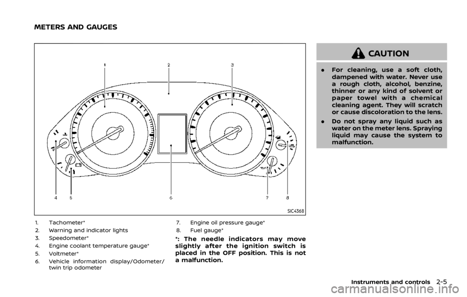
SIC4368
1. Tachometer (P.2-7)
2. Warning and indicator lights (P.2-10)
3. Speedometer (P.2-6)
4. Engine coolant temperature gauge (P.2-7)
5. Voltmeter (P.2-9)
6. Vehicle information display (P.2-20)/Od-ometer/twin trip odometer (P.2-6) 7. Engine oil pressure gauge (P.2-8)
8. Fuel gauge (P.2-8)
METERS AND GAUGES
Page 17 of 528

JVC0965X
VK56VD ENGINE
1. Window washer fluid reservoir (P.8-10)
2. Fuse/fusible link holder (P.8-18)
3. Engine oil dipstick (P.8-6)
4. Power steering fluid reservoir (P.8-8)
5. Engine oil filler cap (P.8-6)
6. Brake fluid reservoir (P.8-9)7. Fuse/fusible link holder (P.8-18)
8. Battery (P.8-11)
9. Radiator filler cap (P.8-4)
10. Engine coolant reservoir (P.8-4)
11. Drive belts (P.8-13)
12. Air cleaner (P.8-15)
Illustrated table of contents0-9
ENGINE COMPARTMENT
Page 91 of 528

2 Instruments and controls
Cockpit ........................................................................\
.......................... 2-3
Instrument panel ........................................................................\
.. 2-4
Meters and gauges ..................................................................... 2-5Speedometer and odometer ........................................ 2-6
Tachometer ........................................................................\
........ 2-7
Engine coolant temperature gauge ....................... 2-7
Fuel gauge ........................................................................\
........... 2-8
Engine oil pressure gauge .............................................. 2-8
Voltmeter ........................................................................\
.............. 2-9
Meter/ring illumination and needle sweep ....... 2-9
Warning lights, indicator lights and audible
reminders ........................................................................\
................. 2-10 Checking lights ..................................................................... 2-11
Warning lights ........................................................................\
2-11
Indicator lights ...................................................................... 2-17
Audible reminders .............................................................. 2-20
Vehicle information display ............................................... 2-20 Operational indicators .................................................... 2-23
Maintenance indicators ................................................. 2-26
Trip computer ........................................................................\
2-28
Security systems ........................................................................\
2-30 Vehicle Security System ................................................ 2-30
NISSAN Vehicle Immobilizer System .................... 2-31 Wiper and washer switch ................................................... 2-33
Windshield wiper and washer operation ...... 2-34
Rain-sensing auto wiper system
(if so equipped) ................................................................... 2-34
Rear window wiper and
washer operation ............................................................. 2-36
Rear window and outside mirror defroster
switch ........................................................................\
......................... 2-36
Windshield deicer switch (if so equipped) ............. 2-36
Headlight and turn signal switch ................................ 2-37 Headlight switch ............................................................... 2-37
Instrument brightness control .............................. 2-40
Turn signal switch ........................................................... 2-41
Fog light switch (if so equipped) ......................... 2-41
Heated steering wheel (if so equipped) .................. 2-42
Horn ........................................................................\
............................. 2-42
Heated seats ........................................................................\
......... 2-43 Front (if so equipped) .................................................... 2-43
Rear (if so equipped) ...................................................... 2-44
Climate controlled seats (if so equipped) ............. 2-45
Warning systems switch (if so equipped) ............. 2-46
SNOW mode switch ................................................................ 2-46
TOW mode switch .................................................................... 2-47
Vehicle Dynamic Control (VDC) OFF switch ........ 2-47
Page 95 of 528

SIC4368
1. Tachometer*
2. Warning and indicator lights
3. Speedometer*
4. Engine coolant temperature gauge*
5. Voltmeter*
6. Vehicle information display/Odometer/twin trip odometer 7. Engine oil pressure gauge*
8. Fuel gauge*
*: The needle indicators may move
slightly after the ignition switch is
placed in the OFF position. This is not
a malfunction.
CAUTION
.
For cleaning, use a soft cloth,
dampened with water. Never use
a rough cloth, alcohol, benzine,
thinner or any kind of solvent or
paper towel with a chemical
cleaning agent. They will scratch
or cause discoloration to the lens.
. Do not spray any liquid such as
water on the meter lens. Spraying
liquid may cause the system to
malfunction.
Instruments and controls2-5
METERS AND GAUGES
Page 97 of 528

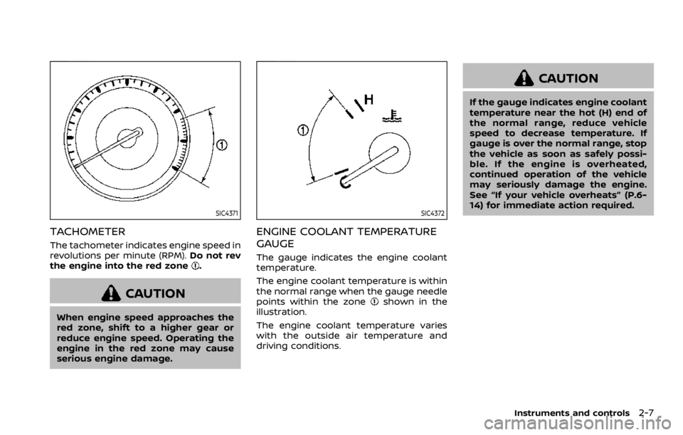
SIC4371
TACHOMETER
The tachometer indicates engine speed in
revolutions per minute (RPM).Do not rev
the engine into the red zone
.
CAUTION
When engine speed approaches the
red zone, shift to a higher gear or
reduce engine speed. Operating the
engine in the red zone may cause
serious engine damage.
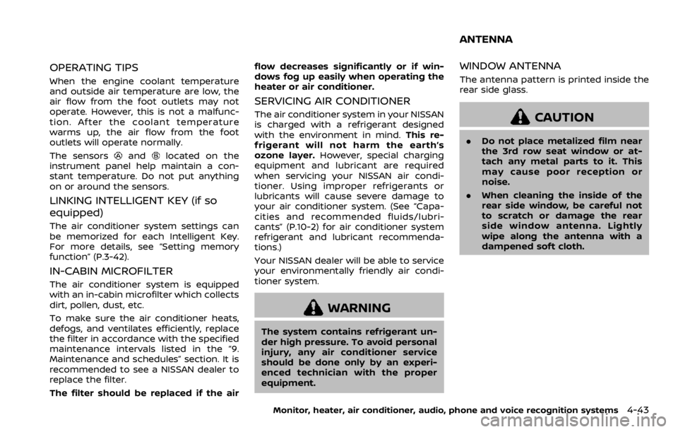
SIC4372
ENGINE COOLANT TEMPERATURE
GAUGE
The gauge indicates the engine coolant
temperature.
The engine coolant temperature is within
the normal range when the gauge needle
points within the zone
shown in the
illustration.
The engine coolant temperature varies
with the outside air temperature and
driving conditions.
CAUTION
If the gauge indicates engine coolant
temperature near the hot (H) end of
the normal range, reduce vehicle
speed to decrease temperature. If
gauge is over the normal range, stop
the vehicle as soon as safely possi-
ble. If the engine is overheated,
continued operation of the vehicle
may seriously damage the engine.
See “If your vehicle overheats” (P.6-
14) for immediate action required.
Instruments and controls2-7
Page 255 of 528

OPERATING TIPS
When the engine coolant temperature
and outside air temperature are low, the
air flow from the foot outlets may not
operate. However, this is not a malfunc-
tion. After the coolant temperature
warms up, the air flow from the foot
outlets will operate normally.
The sensors
andlocated on the
instrument panel help maintain a con-
stant temperature. Do not put anything
on or around the sensors.
LINKING INTELLIGENT KEY (if so
equipped)
The air conditioner system settings can
be memorized for each Intelligent Key.
For more details, see “Setting memory
function” (P.3-42).
IN-CABIN MICROFILTER
The air conditioner system is equipped
with an in-cabin microfilter which collects
dirt, pollen, dust, etc.
To make sure the air conditioner heats,
defogs, and ventilates efficiently, replace
the filter in accordance with the specified
maintenance intervals listed in the “9.
Maintenance and schedules” section. It is
recommended to see a NISSAN dealer to
replace the filter.
The filter should be replaced if the air flow decreases significantly or if win-
dows fog up easily when operating the
heater or air conditioner.
SERVICING AIR CONDITIONER
The air conditioner system in your NISSAN
is charged with a refrigerant designed
with the environment in mind.
This re-
frigerant will not harm the earth’s
ozone layer. However, special charging
equipment and lubricant are required
when servicing your NISSAN air condi-
tioner. Using improper refrigerants or
lubricants will cause severe damage to
your air conditioner system. (See “Capa-
cities and recommended fluids/lubri-
cants” (P.10-2) for air conditioner system
refrigerant and lubricant recommenda-
tions.)
Your NISSAN dealer will be able to service
your environmentally friendly air condi-
tioner system.
WARNING
The system contains refrigerant un-
der high pressure. To avoid personal
injury, any air conditioner service
should be done only by an experi-
enced technician with the proper
equipment.
WINDOW ANTENNA
The antenna pattern is printed inside the
rear side glass.
CAUTION
. Do not place metalized film near
the 3rd row seat window or at-
tach any metal parts to it. This
may cause poor reception or
noise.
. When cleaning the inside of the
rear side window, be careful not
to scratch or damage the rear
side window antenna. Lightly
wipe along the antenna with a
dampened soft cloth.
Monitor, heater, air conditioner, audio, phone and voice recognition systems4-43
ANTENNA
Page 259 of 528

TOW mode ........................................................................\
.......... 5-126
SNOW mode ........................................................................\
....... 5-127
Sonar system (if so equipped) .................................... 5-127Sonar settings ................................................................... 5-128
Sonar indicator ................................................................. 5-129
Power steering ........................................................................\
5-130
Brake system ........................................................................\
.... 5-130 Braking precautions ..................................................... 5-130
Parking brake break-in ............................................... 5-131
Brake assist ........................................................................\
........ 5-131 Brake assist ........................................................................\
. 5-131
Anti-lock Braking System (ABS) ........................... 5-131 Vehicle Dynamic Control (VDC) system .............. 5-133
Vehicle Dynamic Control (VDC)
OFF switch ........................................................................\
. 5-134
Cold weather driving ......................................................... 5-135
Freeing a frozen door lock ................................... 5-135
Antifreeze ........................................................................\
.... 5-135
Battery ........................................................................\
........... 5-135
Draining of coolant water ..................................... 5-135
Tire equipment ............................................................... 5-135
Special winter equipment ..................................... 5-136
Driving on snow or ice ............................................. 5-136
Engine block heater (if so equipped) ........... 5-136
Page 272 of 528

5-16Starting and driving
.Make sure the area around the vehicle
is clear.
. Check fluid levels such as engine oil,
coolant, brake fluid and window
washer fluid as frequently as possible,
or at least whenever you refuel.
. Check that all windows and lights are
clean.
. Visually inspect tires for their appear-
ance and condition. Also check tires
for proper inflation.
. Lock all doors.
. Position seat and adjust head re-
straints/headrests.
. Adjust inside and outside mirrors.
. Fasten seat belts and ask all passen-
gers to do likewise.
. Check the operation of warning lights
when the ignition switch is pushed to
the ON position. (See “Warning lights,
indicator lights and audible remin-
ders” (P.2-10).) 1. Apply the parking brake.
2. Move the shift lever to the P (Park) or N
(Neutral) position. (P is recommended.)
The starter is designed not to operate
unless the shift lever is in either of the
above positions.
3. Push the ignition switch to the ON position. Firmly depress the brake
pedal and push the ignition switch to
start the engine.
To start the engine immediately, push
and release the ignition switch while
depressing the brake pedal with the
ignition switch in any position.
.If the engine is very hard to start inextremely cold weather or when
restarting, depress the accelerator
pedal a little (approximately 1/3 to
the floor) and while holding, crank
the engine. Release the accelerator
pedal when the engine starts.
.If the engine is very hard to startbecause it is flooded, depress the
accelerator pedal all the way to the
floor and hold it. Push the ignition
switch to the ON position to start
cranking the engine. After 5 or 6
seconds, stop cranking by pushing
the ignition switch to OFF. After
cranking the engine, release the
accelerator pedal. Crank the engine
with your foot off the accelerator pedal
by depressing the brake
pedal and pushing the push-button
ignition switch to start the engine.
If the engine starts, but fails to run,
repeat the above procedure.
CAUTION
Do not operate the starter for more
than 15 seconds at a time. If the
engine does not start, push the
ignition switch to OFF and wait 10
seconds before cranking again,
otherwise the starter could be da-
maged.
4. Warm-up
Allow the engine to idle for at least 30
seconds after starting. Do not race the
engine while warming it up. Drive at
moderate speed for a short distance
first, especially in cold weather. In cold
weather, keep the engine running for
a minimum of 2 - 3 minutes before
shutting it off. Starting and stopping
the engine over a short period of time
may make the vehicle more difficult to
start.
When racing the engine up to 4,000
rpm or more under the no load
condition, the engine will enter the
BEFORE STARTING THE ENGINE STARTING THE ENGINE
Page 273 of 528

fuel cut mode.
5. To stop the engine, shift the shift lever to the P (Park) position and push the
ignition switch to the OFF position.
In preparation for the next engine start,
the engine may have a slightly delayed
shutoff after placing the ignition switch in
the OFF position, depending on the driv-
ing conditions.
NOTE:
Care should be taken to avoid situations
that can lead to potential battery dis-
charge and potential no-start condi-
tions such as:
1. Installation or extended use of elec-
tronic accessories that consume
battery power when the engine is
not running (Phone chargers, GPS,
DVD players, etc.)
2. Vehicle is not driven regularly and/
or only driven short distances.
In these cases, the battery may need to
be charged to maintain battery health.
REMOTE ENGINE START (if so
equipped)
Vehicles started with the remote engine
start function require the ignition switch
to be placed in the ON position before the
shift lever can be moved from the P (Park)
position. To place the ignition switch in the ON position, perform the following
steps:
1. Make sure that the Intelligent Key is
on you.
2. Firmly depress the brake pedal.
3. Push the ignition switch once to the ON position.
For additional information about the
remote engine start function, see “Re-
mote engine start” (P.3-19).
ENGINE PROTECTION MODE
The engine has an engine protection
mode to reduce the chance of damage
if the coolant temperature becomes too
high (for example, when climbing steep
grades in high temperature with heavy
loads, such as when towing a trailer).
When the engine temperature reaches a
certain level:
. The engine coolant temperature
gauge will move toward the H posi-
tion.
. Engine power may be reduced.
. The air conditioning cooling function
may be automatically turned OFF for a
short time (the blower will continue to
operate).
Engine power and, under some condi-
tions, vehicle speed will decrease. Vehicle
speed can be controlled with the accel-
erator pedal, but the vehicle may not
accelerate at the desired speed. The
transmission will downshift or upshift as
it reaches prescribed shift points. You can
also shift manually.
As driving conditions change and engine
coolant temperature is reduced, vehicle
speed can be increased using the accel-
erator pedal, and air conditioning cooling
function will automatically be turned
back ON.
Starting and driving5-17
DRIVING THE VEHICLE
Page 274 of 528

5-18Starting and driving
If:
1. The engine coolant temperature is notreduced.
2. The air conditioning cooling function does not turn back ON.
3. The engine oil pressure warning light
illuminates or engine coolant
temperature gauge does not return
to the normal range from the H
position, this may indicate a malfunc-
tion. Move the vehicle off the road to a
safe area and allow the engine to cool.
If after checking the oil and coolant,
the
remains on or engine coolant
temperature does not return to the
normal range, do not continue to
drive. It is recommended you contact
a NISSAN dealer.
The Malfunction Indicator Light (MIL)
may also come ON. You do not need to
have your vehicle towed, unless it re-
mains on, but have it inspected soon. It is
recommended you contact a NISSAN
dealer for this service. See “Warning lights,
indicator lights and audible reminders”
(P.2-10).
WARNING
Overheating can result in reduced
engine power and vehicle speed.
The reduced speed may be lower
than other traffic, which could in-
crease the chance of a collision. Be
especially careful when driving. If the
vehicle cannot maintain a safe driv-
ing speed, pull to the side of the road
in a safe area. Allow the engine to
cool and return to normal operation.
See “If your vehicle overheats” (P.6-
14).
CAUTION
Running the engine with the engine
oil pressure warning light on could
cause serious damage to the engine
almost immediately. Such damage is
not covered by warranty. Turn off the
engine as soon as it is safe to do so.
AUTOMATIC TRANSMISSION
7 speed automatic transmission
The automatic transmission in your vehi-
cle is electronically controlled by a trans-
mission control module to produce
maximum efficiency and smooth opera-
tion.
Shown on the following pages are the
recommended operating procedures for
this transmission. Follow these proce-
dures for maximum vehicle performance
and driving enjoyment.
Starting the vehicle
After starting the engine, fully depress the
foot brake pedal and push the shift lever
button before shifting the shift lever to
the R (Reverse), N (Neutral), D (Drive) or
Manual shift mode position. Be sure the
vehicle is fully stopped before attempting
to shift the shift lever.
This automatic transmission model is
designed so that the foot brake pedal
must be depressed before shifting from
P (Park) to any drive position while the
ignition switch position is ON.
The shift lever cannot be moved out of
the P (Park) position and into any of the
other gear positions if the ignition
switch is pushed to the LOCK, OFF or
ACC position.