sensor NISSAN ARMADA 2023 Owner's Manual
[x] Cancel search | Manufacturer: NISSAN, Model Year: 2023, Model line: ARMADA, Model: NISSAN ARMADA 2023Pages: 604, PDF Size: 2.97 MB
Page 212 of 604
3-24Pre-driving checks and adjustments
Power open
When the liftgate is fully closed, the
liftgate will fully open automatically by:
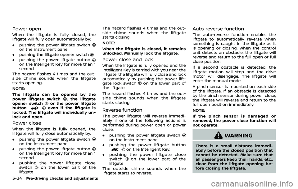
.pushing the power liftgate switch
on the instrument panel
. pushing the liftgate opener switch
.pushing the power liftgate buttonon the Intelligent Key for more than 1
second
The hazard flashes 4 times and the out-
side chime sounds when the liftgate
starts opening.
NOTE:
The liftgate can be opened by the
power liftgate switch
, the liftgate
opener switchor the power liftgate
buttoneven if the liftgate is
locked. The liftgate will individually un-
lock and open.
Power close
When the liftgate is fully opened, the
liftgate will fully close automatically by:
. pushing the power liftgate switch
on the instrument panel
. pushing the power liftgate button
on the Intelligent Key for more than 1
second
. pushing the power liftgate close
switch
on the lower part of the
liftgate The hazard flashes 4 times and the out-
side chime sounds when the liftgate
starts closing.
NOTE:
When the liftgate is closed, it remains
unlocked. Manually lock the liftgate.
Power close and lock
When the liftgate is fully opened and the
Intelligent Key is carried with you near the
liftgate, the liftgate will fully close and lock
automatically by pushing the power lift-
gate lock switch
on the lower part of
the liftgate.
The hazard flashes 4 times and the out-
side chime sounds when the liftgate
starts closing.
Reverse function
The power liftgate will reverse immedi-
ately if one of the following actions is
performed during power open or power
close.
. pushing the power liftgate switch
on the instrument panel
. pushing the power liftgate button
on the Intelligent Key.
. pushing the power liftgate close
switch
on the lower part of the
liftgate
The outside chime sounds when the
liftgate starts to reverse.
Auto reverse function
The auto-reverse function enables the
liftgate to automatically reverse when
something is caught in the liftgate as it
is opening or closing. When the control
unit detects an obstacle, the liftgate will
reverse and return to the full open or full
close position.
If a second obstacle is detected, the
liftgate motion will stop and the drive
motor will disengage. The liftgate will
enter the manual mode.
A pinch sensor is mounted on each side
of the liftgate. If an obstacle is detected
by the pinch sensor during power close,
the liftgate will reverse and return to the
full open position immediately.
NOTE:
If the pinch sensor is damaged or
removed, the power close function will
not operate.
WARNING
There is a small distance immedi-
ately before the closed position that
cannot be detected. Make sure that
all passengers keep their hands, etc.,
clear from the liftgate opening be-
fore closing the liftgate.
Page 219 of 604
SPA2450-A
Automatic anti-glare type (if so
equipped)
The inside mirror is designed so that it
automatically changes reflection accord-
ing to the intensity of the headlights of
the following vehicle.
The anti-glare system will be automati-
cally turned on when the ignition switch is
placed in the ON position.
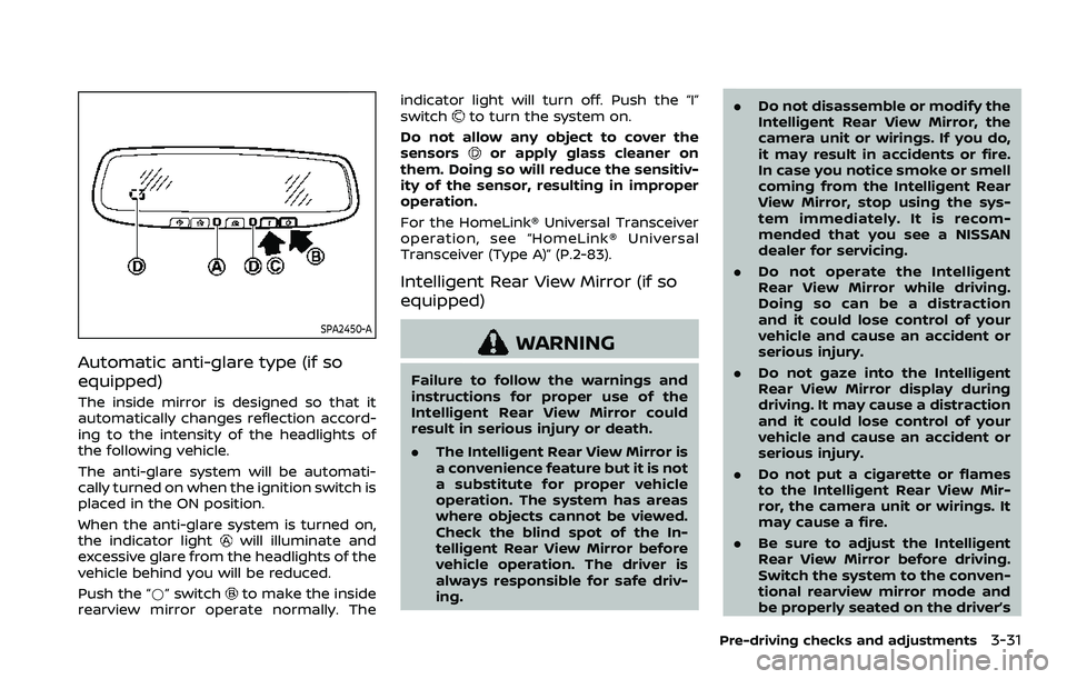
When the anti-glare system is turned on,
the indicator light
will illuminate and
excessive glare from the headlights of the
vehicle behind you will be reduced.
Push the “*” switch
to make the inside
rearview mirror operate normally. The indicator light will turn off. Push the “I”
switch
to turn the system on.
Do not allow any object to cover the
sensors
or apply glass cleaner on
them. Doing so will reduce the sensitiv-
ity of the sensor, resulting in improper
operation.
For the HomeLink® Universal Transceiver
operation, see “HomeLink® Universal
Transceiver (Type A)” (P.2-83).
Intelligent Rear View Mirror (if so
equipped)
WARNING
Failure to follow the warnings and
instructions for proper use of the
Intelligent Rear View Mirror could
result in serious injury or death.
. The Intelligent Rear View Mirror is
a convenience feature but it is not
a substitute for proper vehicle
operation. The system has areas
where objects cannot be viewed.
Check the blind spot of the In-
telligent Rear View Mirror before
vehicle operation. The driver is
always responsible for safe driv-
ing. .
Do not disassemble or modify the
Intelligent Rear View Mirror, the
camera unit or wirings. If you do,
it may result in accidents or fire.
In case you notice smoke or smell
coming from the Intelligent Rear
View Mirror, stop using the sys-
tem immediately. It is recom-
mended that you see a NISSAN
dealer for servicing.
. Do not operate the Intelligent
Rear View Mirror while driving.
Doing so can be a distraction
and it could lose control of your
vehicle and cause an accident or
serious injury.
. Do not gaze into the Intelligent
Rear View Mirror display during
driving. It may cause a distraction
and it could lose control of your
vehicle and cause an accident or
serious injury.
. Do not put a cigarette or flames
to the Intelligent Rear View Mir-
ror, the camera unit or wirings. It
may cause a fire.
. Be sure to adjust the Intelligent
Rear View Mirror before driving.
Switch the system to the conven-
tional rearview mirror mode and
be properly seated on the driver’s
Pre-driving checks and adjustments3-31
Page 260 of 604
4-30Monitor, heater, air conditioner, audio, phone and voice recognition systems
SONAR SYSTEM LIMITATIONS
WARNING
Listed below are the system limita-
tions for the sonar function. Failure
to operate the vehicle in accordance
with these system limitations could
result in serious injury or death.
.Inclement weather or ultrasonic
sources such as an automatic car
wash, a truck’s compressed-air
brakes or a pneumatic drill may
affect the function of the system,
including reduced performance
or a false activation.
. The system is not designed to
prevent contact with small or
moving objects.
. The system will not detect small
objects below the bumper, and
may not detect objects close to
the bumper or on the ground.
. The system may not detect the
following objects:
— Fluffy objects such as snow,
cloth, cotton, grass or wool.
— Thin objects such as rope, wire or chain. — Wedge-shaped objects.
. If your vehicle sustains damage
to the bumper fascia, leaving it
misaligned or bent, the sensing
zone may be altered causing in-
accurate measurement of objects
or false alarms.
CAUTION
Excessive noise (such as audio sys-
tem volume or an open vehicle win-
dow) will interfere with the tone and
it may not be heard.
See “Front and rear sonar system” (P.5-
136) for more information on the sonar
system and limitations.
System temporarily unavailable
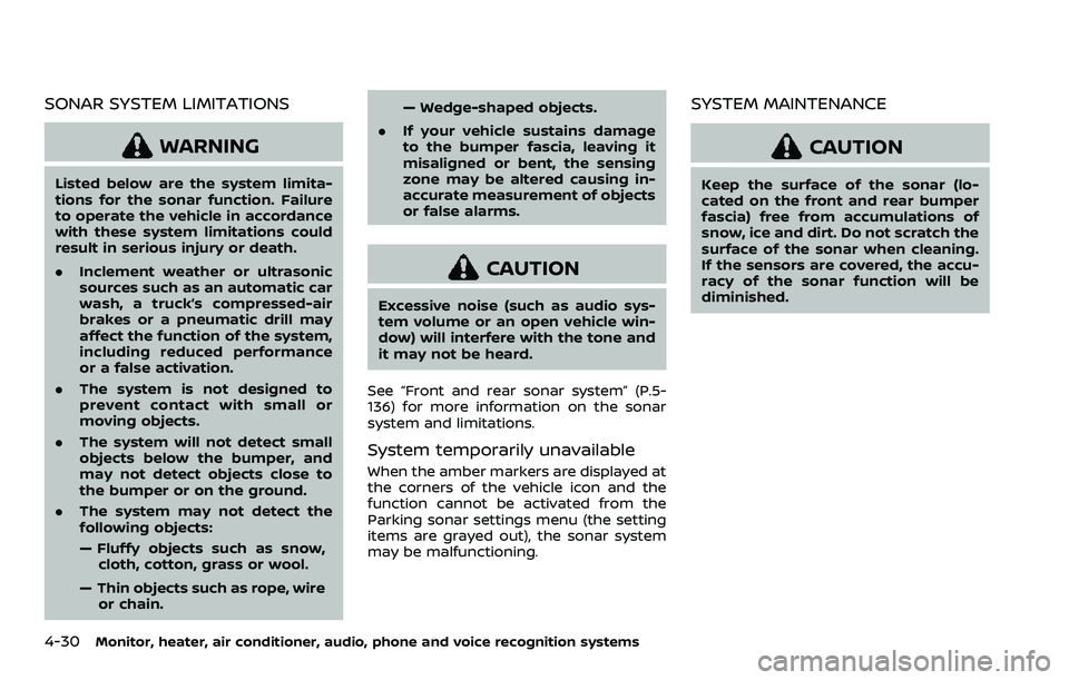
When the amber markers are displayed at
the corners of the vehicle icon and the
function cannot be activated from the
Parking sonar settings menu (the setting
items are grayed out), the sonar system
may be malfunctioning.
SYSTEM MAINTENANCE
CAUTION
Keep the surface of the sonar (lo-
cated on the front and rear bumper
fascia) free from accumulations of
snow, ice and dirt. Do not scratch the
surface of the sonar when cleaning.
If the sensors are covered, the accu-
racy of the sonar function will be
diminished.
Page 273 of 604
OPERATING TIPS
When the engine coolant temperature
and outside air temperature are low, the
air flow from the foot outlets may not
operate. However, this is not a malfunc-
tion. After the coolant temperature
warms up, the air flow from the foot
outlets will operate normally.
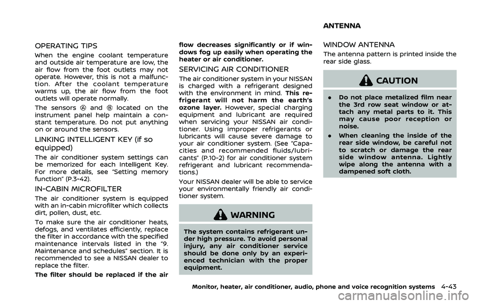
The sensors
andlocated on the
instrument panel help maintain a con-
stant temperature. Do not put anything
on or around the sensors.
LINKING INTELLIGENT KEY (if so
equipped)
The air conditioner system settings can
be memorized for each Intelligent Key.
For more details, see “Setting memory
function” (P.3-42).
IN-CABIN MICROFILTER
The air conditioner system is equipped
with an in-cabin microfilter which collects
dirt, pollen, dust, etc.
To make sure the air conditioner heats,
defogs, and ventilates efficiently, replace
the filter in accordance with the specified
maintenance intervals listed in the “9.
Maintenance and schedules” section. It is
recommended to see a NISSAN dealer to
replace the filter.
The filter should be replaced if the air flow decreases significantly or if win-
dows fog up easily when operating the
heater or air conditioner.
SERVICING AIR CONDITIONER
The air conditioner system in your NISSAN
is charged with a refrigerant designed
with the environment in mind.
This re-
frigerant will not harm the earth’s
ozone layer. However, special charging
equipment and lubricant are required
when servicing your NISSAN air condi-
tioner. Using improper refrigerants or
lubricants will cause severe damage to
your air conditioner system. (See “Capa-
cities and recommended fluids/lubri-
cants” (P.10-2) for air conditioner system
refrigerant and lubricant recommenda-
tions.)
Your NISSAN dealer will be able to service
your environmentally friendly air condi-
tioner system.
WARNING
The system contains refrigerant un-
der high pressure. To avoid personal
injury, any air conditioner service
should be done only by an experi-
enced technician with the proper
equipment.
WINDOW ANTENNA
The antenna pattern is printed inside the
rear side glass.
CAUTION
. Do not place metalized film near
the 3rd row seat window or at-
tach any metal parts to it. This
may cause poor reception or
noise.
. When cleaning the inside of the
rear side window, be careful not
to scratch or damage the rear
side window antenna. Lightly
wipe along the antenna with a
dampened soft cloth.
Monitor, heater, air conditioner, audio, phone and voice recognition systems4-43
ANTENNA
Page 306 of 604
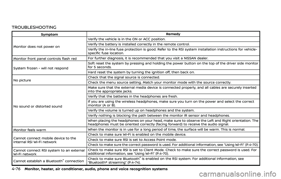
4-76Monitor, heater, air conditioner, audio, phone and voice recognition systems
TROUBLESHOOTING
SymptomRemedy
Monitor does not power on Verify the vehicle is in the ON or ACC position.
Verify the battery is installed correctly in the remote control.
Verify the in-line fuse protection is good. Refer to the RSI system installation instructions for vehicle-
specific fuse location.
Monitor front panel controls flash red For further diagnosis, it is recommended that you visit a NISSAN dealer.
System frozen - will not respond Soft reset the system by pressing and holding the power button on the top of the driver side monitor
for 5 seconds.
Hard reset the system by turning the ignition off, then back on.
No picture Check that the signal source is connected.
Check the menu source setting. Match your monitor mode with the source correctly.
No sound or distorted sound Make sure that the external media device is connected properly, and all cables are securely inserted
into the appropriate jacks.
Verify that the batteries in the headphones are fresh.
If you are using the wireless headphones, make sure you turn on the power and select the correct
monitor (A or B).
Verify the volume is turned up on headphones and the system.
Verify nothing is blocking the path between the monitor IR sensor and headphones.
When placing the headphones on your head, make sure to observe the Left and Right orientation. The
headphones must be oriented correctly (facing forward) to receive the audio signal.
Monitor feels warm When the monitor is in use for a long period of time, the surface will be warm. This is normal.
Cannot connect mobile device to the
internal RSI Wi-Fi network Check to make sure Wi-Fi is enabled on the mobile device.
Check to make sure RSI is set to Access Point mode.
Check to make sure the correct password is used. For additional information, see “Using Wi-Fi” (P.4-70).
Cannot connect RSI system to an external
Wi-Fi network Check to make sure RSI is set to Client Mode. Check to make sure the correct password is used. For
additional information, see “Using Wi-Fi” (P.4-70).
Cannot establish a Bluetooth
®connection Check to make sure Bluetooth®is enabled on the RSI system. For additional information, see
“Bluetooth® streaming” (P.4-74).
Page 319 of 604
recommended you consult a
NISSAN dealer.
. Since the spare tire is not
equipped with the TPMS, when a
spare tire is mounted or a wheel
is replaced, the TPMS will not
function and the low tire pressure
warning light will flash for ap-
proximately 1 minute. The light
will remain on after 1 minute.
Have your tires replaced and/or
TPMS system reset as soon as
possible. It is recommended you
visit a NISSAN dealer for these
services.
. Replacing tires with those not
originally specified by NISSAN
could affect the proper operation
of the TPMS.
. Do not inject any tire liquid or
aerosol tire sealant into the tires,
as this may cause a malfunction
of the tire pressure sensors.
CAUTION
.The TPMS may not function prop-
erly when the wheels are
equipped with tire chains or the
wheels are buried in snow. .
Do not place metalized film or
any metal parts (antenna, etc.) on
the windows. This may cause
poor reception of the signals
from the tire pressure sensors,
and the TPMS will not function
properly.
Some devices and transmitters may tem-
porarily interfere with the operation of
the TPMS and cause the low tire pressure
warning light to illuminate. Some exam-
ples are:
. Facilities or electric devices using
similar radio frequencies are near the
vehicle.
. If a transmitter set to similar frequen-
cies is being used in or near the
vehicle.
. If a computer (or similar equipment) or
a DC/AC converter is being used in or
near the vehicle.
Low tire pressure warning light may
illuminate in the following cases.
. If the vehicle is equipped with a wheel
and tire without TPMS.
. If the TPMS has been replaced and the
ID has not been registered.
. If the wheel is not originally specified
by NISSAN. FCC Notice:
For USA:
This device complies with Part 15 of the
FCC Rules. Operation is subject to the
following two conditions: (1) This device
may not cause harmful interference,
and (2) this device must accept any
interference received, including inter-
ference that may cause undesired op-
eration.
Note: Changes or modifications not
expressly approved by the party re-
sponsible for compliance could void
the user’s authority to operate the
equipment.
For Canada:
This device complies with Industry Ca-
nada licence-exempt RSS standard(s).
Operation is subject to the following
two conditions: (1) this device may not
cause interference, and (2) this device
must accept any interference, including
interference that may cause undesired
operation of the device.
Starting and driving5-7
Page 350 of 604
5-38Starting and driving
WARNING
Failure to follow the warnings and
instructions for proper use of the
BSW system could result in serious
injury or death.
.The BSW system is not a replace-
ment for proper driving proce-
dure and is not designed to
prevent contact with vehicles or
objects. When changing lanes, al-
ways use the side and rear mir-
rors and turn and look in the
direction your vehicle will move
to ensure it is safe to change
lanes. Never rely solely on the
BSW system.
The BSW system helps alert the driver of
other vehicles in adjacent lanes when
changing lanes.
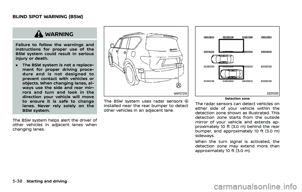
WAF0721X
The BSW system uses radar sensorsinstalled near the rear bumper to detect
other vehicles in an adjacent lane.
SSD1030
Detection zone
The radar sensors can detect vehicles on
either side of your vehicle within the
detection zone shown as illustrated. This
detection zone starts from the outside
mirror of your vehicle and extends ap-
proximately 10 ft (3.0 m) behind the rear
bumper, and approximately 10 ft (3.0 m)
sideways.
When the turn signal is activated, the
detection zone may extend more than
approximately 10 ft (3.0 m).
BLIND SPOT WARNING (BSW)
Page 351 of 604
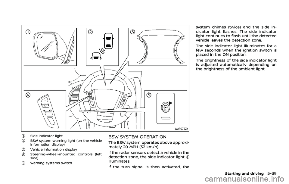
WAF0722X
Side indicator lightBSW system warning light (on the vehicle
information display)
Vehicle information displaySteering-wheel-mounted controls (left
side)
Warning systems switch
BSW SYSTEM OPERATION
The BSW system operates above approxi-
mately 20 MPH (32 km/h).
If the radar sensors detect a vehicle in the
detection zone, the side indicator light
illuminates.
If the turn signal is then activated, thesystem chimes (twice) and the side in-
dicator light flashes. The side indicator
light continues to flash until the detected
vehicle leaves the detection zone.
The side indicator light illuminates for a
few seconds when the ignition switch is
placed in the ON position.
The brightness of the side indicator light
is adjusted automatically depending on
the brightness of the ambient light.
Starting and driving5-39
Page 353 of 604
.The radar sensors may not be
able to detect and activate BSW
when certain objects are present
such as:
— Pedestrians, bicycles, animals.
— Vehicles such as motorcycles,
low height vehicles, or high
ground clearance vehicles.
— Oncoming vehicles.
— Vehicles remaining in the de- tection zone when you accel-
erate from a stop.
— A vehicle merging into an adjacent lane at a speed ap-
proximately the same as your
vehicle.
— A vehicle approaching rapidly from behind.
— A vehicle which your vehicle overtakes rapidly.
— A vehicle that passes through the detection zone quickly.
— When overtaking several vehi- cles in a row, the vehicles after
the first vehicle may not be
detected if they are traveling
close together. .
The radar sensor’s detection zone
is designed based on a standard
lane width. When driving in a
wider lane, the radar sensors
may not detect vehicles in an
adjacent lane. When driving in a
narrow lane, the radar sensors
may detect vehicles driving two
lanes away.
. The radar sensors are designed
to ignore most stationary objects,
however objects such as guard-
rails, walls, foliage and parked
vehicles may occasionally be de-
tected. This is a normal operation
condition.
. The following conditions may re-
duce the ability of the radar to
detect other vehicles:
— Severe weather
— Road spray
— Ice/frost/dirt build-up on the
vehicle
. Do not attach stickers (including
transparent material), install ac-
cessories or apply additional
paint near the radar sensors.
These conditions may reduce the
ability of the radar to detect other
vehicles. .
When towing a trailer or other
vehicle, turn the BSW system off
to prevent the occurrence of an
unexpected accident resulting
from sudden system operation.
. Excessive noise (for example,
audio system volume, open vehi-
cle window) will interfere with the
chime sound, and it may not be
heard.
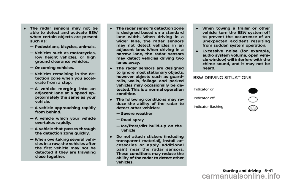
BSW DRIVING SITUATIONS
Indicator on
Indicator off
Indicator flashing
Starting and driving5-41
Page 354 of 604
5-42Starting and driving
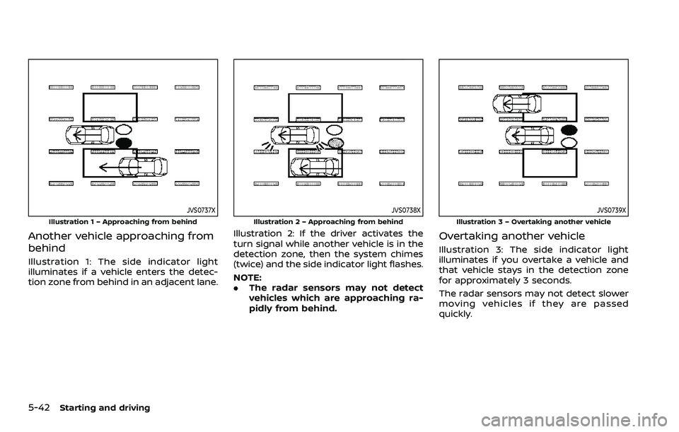
JVS0737X
Illustration 1 – Approaching from behind
Another vehicle approaching from
behind
Illustration 1: The side indicator light
illuminates if a vehicle enters the detec-
tion zone from behind in an adjacent lane.
JVS0738X
Illustration 2 – Approaching from behind
Illustration 2: If the driver activates the
turn signal while another vehicle is in the
detection zone, then the system chimes
(twice) and the side indicator light flashes.
NOTE:
.The radar sensors may not detect
vehicles which are approaching ra-
pidly from behind.
JVS0739X
Illustration 3 – Overtaking another vehicle
Overtaking another vehicle
Illustration 3: The side indicator light
illuminates if you overtake a vehicle and
that vehicle stays in the detection zone
for approximately 3 seconds.
The radar sensors may not detect slower
moving vehicles if they are passed
quickly.