tow NISSAN CUBE 2010 3.G User Guide
[x] Cancel search | Manufacturer: NISSAN, Model Year: 2010, Model line: CUBE, Model: NISSAN CUBE 2010 3.GPages: 329, PDF Size: 2.86 MB
Page 94 of 329
Black plate (94,1)
Model "Z12-D" EDITED: 2009/ 9/ 17
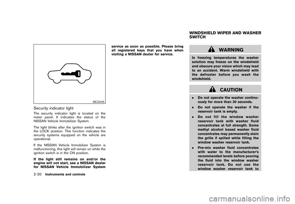
SIC2045
Security indicator lightThe security indicator light is located on the
meter panel. It indicates the status of the
NISSAN Vehicle Immobilizer System.
The light blinks after the ignition switch was in
the LOCK position. This function indicates the
security systems equipped on the vehicle are
operational.
If the NISSAN Vehicle Immobilizer System is
malfunctioning, this light will remain on while the
ignition switch is in the ON position.
If the light still remains on and/or the
engine will not start, see a NISSAN dealer
for NISSAN Vehicle Immobilizer Systemservice as soon as possible. Please bring
all registered keys that you have when
visiting a NISSAN dealer for service.
WARNING
In freezing temperatures the washer
solution may freeze on the windshield
and obscure your vision which may lead
to an accident. Warm windshield with
the defroster before you wash the
windshield.
CAUTION
.
Do not operate the washer continu-
ously for more than 30 seconds.
. Do not operate the washer if the
reservoir tank is empty.
. Do not fill the window washer
reservoir tank with washer fluid
concentrates at full strength. Some
methyl alcohol based washer fluid
concentrates may permanently stain
the grille if spilled while filling the
window washer reservoir tank.
. Pre-mix washer fluid concentrates
with water to the manufacturer’s
recommended levels before pouring
the fluid into the window washer
reservoir tank. Do not use the
window washer reservoir tank toWINDSHIELD WIPER AND WASHER
SWITCH
2-20
Instruments and controls
Page 95 of 329
Black plate (95,1)
Model "Z12-D" EDITED: 2009/ 9/ 17
mix the washer fluid concentrate
and water.
If the windshield wiper operation is inter-
rupted by snow or ice, the wiper may stop
moving to protect its motor. If this occurs,
turn the wiper switch to the OFF position
and remove the snow or ice that is on and
around the wiper arms. In approximately 1
minute, turn the switch on again to operate
the wiper.
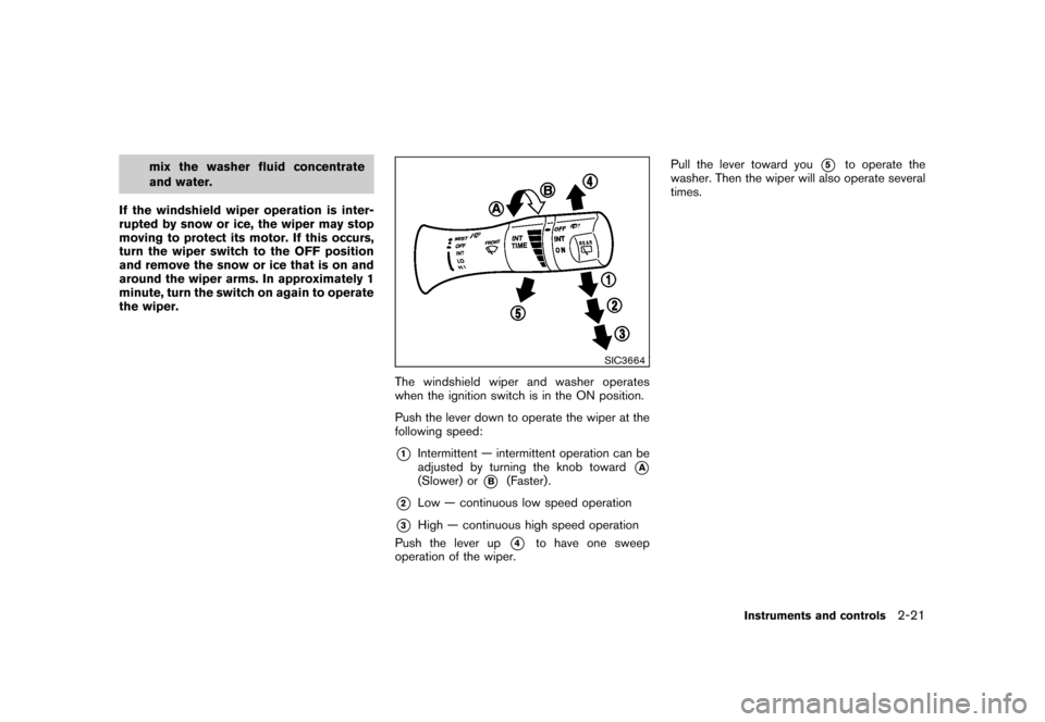
SIC3664
The windshield wiper and washer operates
when the ignition switch is in the ON position.
Push the lever down to operate the wiper at the
following speed:*1
Intermittent — intermittent operation can be
adjusted by turning the knob toward
*A
(Slower) or
*B
(Faster) .
*2
Low — continuous low speed operation
*3
High — continuous high speed operation
Push the lever up
*4
to have one sweep
operation of the wiper. Pull the lever toward you
*5
to operate the
washer. Then the wiper will also operate several
times.
Instruments and controls
2-21
Page 99 of 329
Black plate (99,1)
Model "Z12-D" EDITED: 2009/ 9/ 17
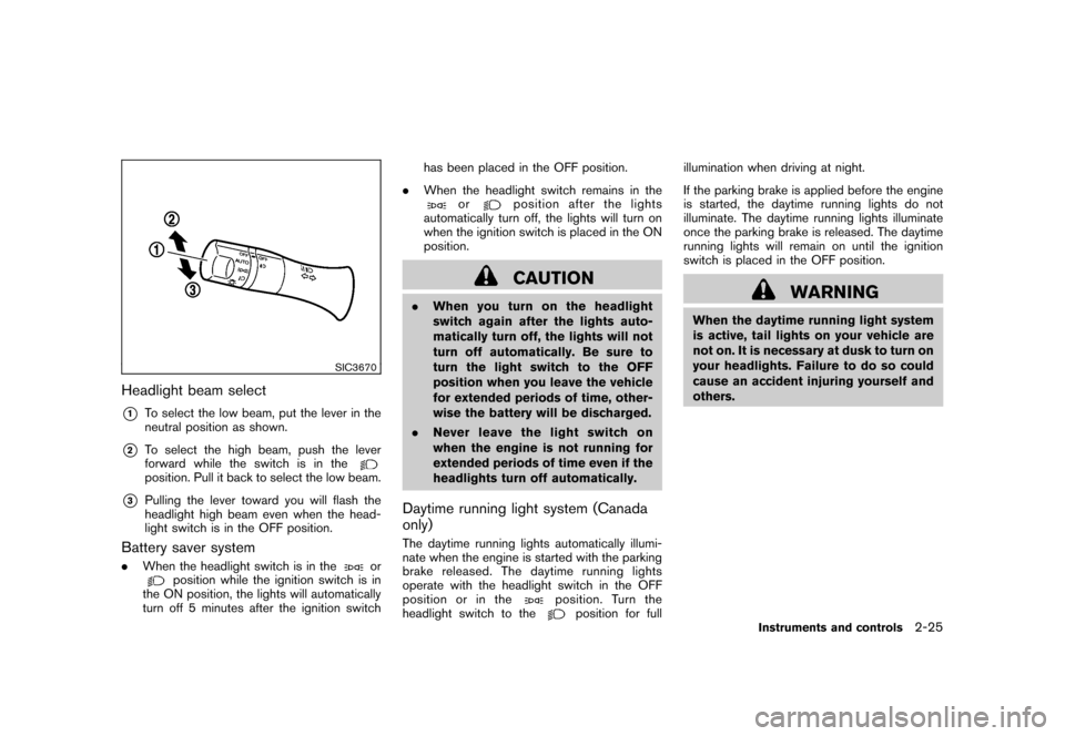
SIC3670
Headlight beam select*1
To select the low beam, put the lever in the
neutral position as shown.
*2
To select the high beam, push the lever
forward while the switch is in theposition. Pull it back to select the low beam.
*3
Pulling the lever toward you will flash the
headlight high beam even when the head-
light switch is in the OFF position.
Battery saver system.When the headlight switch is in the
or
position while the ignition switch is in
the ON position, the lights will automatically
turn off 5 minutes after the ignition switch has been placed in the OFF position.
. When the headlight switch remains in the
or
position after the lights
automatically turn off, the lights will turn on
when the ignition switch is placed in the ON
position.CAUTION
. When you turn on the headlight
switch again after the lights auto-
matically turn off, the lights will not
turn off automatically. Be sure to
turn the light switch to the OFF
position when you leave the vehicle
for extended periods of time, other-
wise the battery will be discharged.
. Never leave the light switch on
when the engine is not running for
extended periods of time even if the
headlights turn off automatically.Daytime running light system (Canada
only)The daytime running lights automatically illumi-
nate when the engine is started with the parking
brake released. The daytime running lights
operate with the headlight switch in the OFF
position or in the
position. Turn the
headlight switch to the
position for full illumination when driving at night.
If the parking brake is applied before the engine
is started, the daytime running lights do not
illuminate. The daytime running lights illuminate
once the parking brake is released. The daytime
running lights will remain on until the ignition
switch is placed in the OFF position.
WARNING
When the daytime running light system
is active, tail lights on your vehicle are
not on. It is necessary at dusk to turn on
your headlights. Failure to do so could
cause an accident injuring yourself and
others.
Instruments and controls
2-25
Page 124 of 329
Black plate (126,1)
Model "Z12-D" EDITED: 2009/ 9/ 17
WARNING
.Radio waves could adversely affect
electric medical equipment. Those
who use a pacemaker should con-
tact the electric medical equipment
manufacturer for the possible influ-
ences before use.
. The Intelligent Key transmits radio
waves when the buttons are
pushed. The FAA advises that the
radio waves may affect aircraft na-
vigation and communication sys-
tems. Do not operate the
Intelligent Key while on an airplane.
Makesurethebuttonsarenot
operated unintentionally when the
unit is stored during a flight.
The Intelligent Key system can operate all the
door locks using the remote controller function
or pushing the request switch on the vehicle
without taking the key out from a pocket or
purse. The operating environment and/or condi-
tions may affect the Intelligent Key system
operation.
Be sure to read the following before using the
Intelligent Key system.
CAUTION
. Be sure to carry the Intelligent Key
with you when operating the vehi-
cle.
. Never leave the Intelligent Key in
the vehicle when you leave the
vehicle.
The Intelligent Key is always communicating with
the vehicle as it receives radio waves. The
Intelligent Key system transmits weak radio
waves. Environmental conditions may interfere
with the operation of the Intelligent Key system
under the following operating conditions.
. When operating near a location where
strong radio waves are transmitted, such
as a TV tower, power station and broad-
casting station.
. When in possession of wireless equipment,
such as a cellular phone, transceiver, and
CB radio.
. When the Intelligent Key is in contact with or
covered by metallic materials.
. When any type of radio wave remote control
is used nearby.
. When the Intelligent Key is placed near an
electric appliance such as a personal computer.
. When the vehicle is parked near a parking
meter.
In such cases, correct the operating conditions
before using the Intelligent Key function or use
the mechanical key.
Although the life of the battery varies depending
on the operating conditions, the battery’s life is
approximately 2 years. If the battery is dis-
charged, replace it with a new one.
Since the Intelligent Key is continuously receiv-
ing radio waves, if the key is left near equipment
which transmits strong radio waves, such as
signals from a TV and personal computer, the
battery life may become shorter.
For information regarding replacement of a
battery, see “KEY BATTERY REPLACEMENT”
in the “8. Maintenance and do-it-yourself”
section.
Because the steering wheel is locked electri-
cally, unlocking the steering wheel with the
ignition switch in the LOCK position is impos-
sible when the vehicle battery is completely
discharged. Always be careful that the vehicle
battery is not completely discharged.
As many as 4 Intelligent Keys can be registered
and used with one vehicle. For information about
the purchase and use of additional Intelligent
INTELLIGENT KEY SYSTEM (if so
equipped)3-10
Pre-driving checks and adjustments
Page 142 of 329
Black plate (144,1)
Model "Z12-D" EDITED: 2009/ 9/ 17
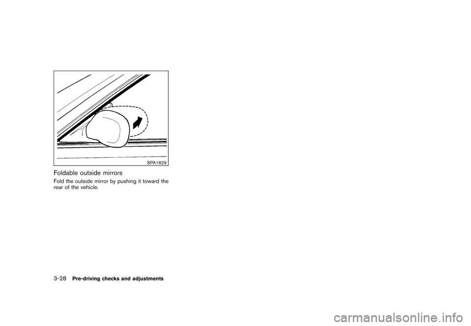
SPA1829
Foldable outside mirrorsFold the outside mirror by pushing it toward the
rear of the vehicle.3-28
Pre-driving checks and adjustments
Page 203 of 329
Black plate (207,1)
Model "Z12-D" EDITED: 2009/ 9/ 17
WARNING
.The exhaust gas and the exhaust
system are very hot. Keep people,
animals or flammable materials
away from the exhaust system com-
ponents.
. Do not stop or park the vehicle over
flammable materials such as dry
grass, waste paper or rags. They
may ignite and cause a fire.
CAUTION
.Do not use leaded gasoline. Depos-
its from leaded gasoline will ser-
iously reduce the three-way
catalyst’s ability to help reduce ex-
haust pollutants.
. Keep your engine tuned up. Mal-
functions in the ignition, fuel injec-
tion, or electrical systems can cause
overrich fuel flow into the three-way
catalyst, causing it to overheat. Do
not keep driving if the engine mis-
fires, or if noticeable loss of perfor-
mance or other unusual operating
conditions are detected. Have the vehicle inspected promptly by a
NISSAN dealer.
. Avoid driving with an extremely low
fuel level. Running out of fuel could
cause the engine to misfire, dama-
ging the three-way catalyst.
. Do not race the engine while warm-
ing it up.
. Do not push or tow your vehicle to
start the engine.
TIRE PRESSURE MONITORING SYS-
TEM (TPMS)Each tire, including the spare (if provided) ,
should be checked monthly when cold and
inflated to the inflation pressure recommended
by the vehicle manufacturer on the vehicle
placard or tire inflation pressure label. (If your
vehicle has tires of a different size than the size
indicated on the vehicle placard or tire inflation
pressure label, you should determine the proper
tire inflation pressure for those tires.)
As an added safety feature, your vehicle has
been equipped with a Tire Pressure Monitoring
System (TPMS) that illuminates a low tire
pressure telltale when one or more of your tires
is significantly under-inflated. Accordingly, when
the low tire pressure telltale illuminates, you
should stop and check your tires as soon as possible, and inflate them to the proper pres-
sure. Driving on a significantly under-inflated tire
causes the tire to overheat and can lead to tire
failure. Under-inflation also reduces fuel effi-
ciency and tire tread life, and may affect the
vehicle’s handling and stopping ability.
Please note that the TPMS is not a substitute for
proper tire maintenance, and it is the driver’s
responsibility to maintain correct tire pressure,
even if under-inflation has not reached the level
to trigger illumination of the TPMS low tire
pressure telltale.
Your vehicle has also been equipped with a
TPMS malfunction indicator to indicate when the
system is not operating properly. The TPMS
malfunction indicator is combined with the low
tire pressure telltale. When the system detects a
malfunction, the telltale will flash for approxi-
mately one minute and then remain continuously
illuminated. This sequence will continue upon
subsequent vehicle start-ups as long as the
malfunction exists. When the malfunction indi-
cator is illuminated, the system may not be able
to detect or signal low tire pressure as intended.
TPMS malfunctions may occur for a variety of
reasons, including the installation of replace-
ment or alternate tires or wheels on the vehicle
that prevent the TPMS from functioning properly.
Always check the TPMS malfunction telltale
after replacing one or more tires or wheels on
your vehicle to ensure that the replacement or
Starting and driving
5-3
Page 210 of 329
Black plate (214,1)
Model "Z12-D" EDITED: 2009/ 9/ 17
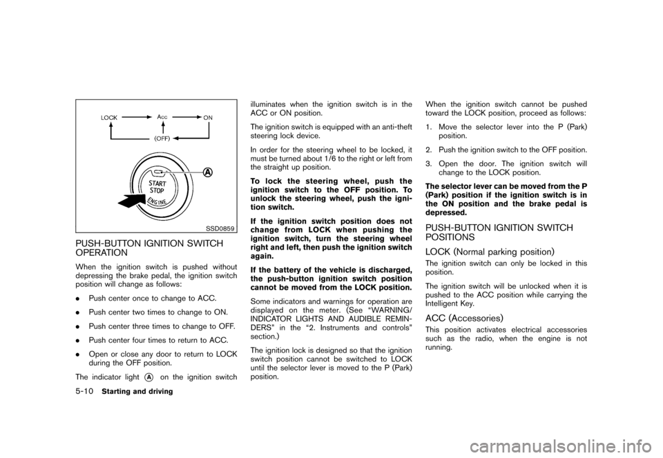
SSD0859
PUSH-BUTTON IGNITION SWITCH
OPERATIONWhen the ignition switch is pushed without
depressing the brake pedal, the ignition switch
position will change as follows:
.Push center once to change to ACC.
. Push center two times to change to ON.
. Push center three times to change to OFF.
. Push center four times to return to ACC.
. Open or close any door to return to LOCK
during the OFF position.
The indicator light
*A
on the ignition switch illuminates when the ignition switch is in the
ACC or ON position.
The ignition switch is equipped with an anti-theft
steering lock device.
In order for the steering wheel to be locked, it
must be turned about 1/6 to the right or left from
the straight up position.
To lock the steering wheel, push the
ignition switch to the OFF position. To
unlock the steering wheel, push the igni-
tion switch.
If the ignition switch position does not
change from LOCK when pushing the
ignition switch, turn the steering wheel
right and left, then push the ignition switch
again.
If the battery of the vehicle is discharged,
the push-button ignition switch position
cannot be moved from the LOCK position.
Some indicators and warnings for operation are
displayed on the meter. (See “WARNING/
INDICATOR LIGHTS AND AUDIBLE REMIN-
DERS” in the “2. Instruments and controls”
section.)
The ignition lock is designed so that the ignition
switch position cannot be switched to LOCK
until the selector lever is moved to the P (Park)
position.
When the ignition switch cannot be pushed
toward the LOCK position, proceed as follows:
1. Move the selector lever into the P (Park)
position.
2. Push the ignition switch to the OFF position.
3. Open the door. The ignition switch will change to the LOCK position.
The selector lever can be moved from the P
(Park) position if the ignition switch is in
the ON position and the brake pedal is
depressed.
PUSH-BUTTON IGNITION SWITCH
POSITIONS
LOCK (Normal parking position)The ignition switch can only be locked in this
position.
The ignition switch will be unlocked when it is
pushed to the ACC position while carrying the
Intelligent Key.ACC (Accessories)This position activates electrical accessories
such as the radio, when the engine is not
running.
5-10
Starting and driving
Page 225 of 329
Black plate (229,1)
Model "Z12-D" EDITED: 2009/ 9/ 17
Turn the wheels toward the side of the road
so the vehicle will move away from the
center of the road if it moves.
4. Models with Intelligent Key system:
Place the ignition switch in the OFF position.
Models without Intelligent Key system:
Place the ignition switch in the LOCK
position and remove the key.
WARNING
.If the engine is not running or is
turned off while driving, the power
assist for the steering will not work.
Steering will be harder to operate.
. When the electric power steering
warning light illuminates with the
engine running, the power assist for
the steering will cease operation.
You will still have control of the
vehicle but the steering will be
harder to operate.
The electric power steering system is designed
to provide power assist while driving to operate
the steering wheel with light force.
When the steering wheel is operated repeatedly
or continuously while parking or driving at a very
low speed, the power assist for the steering
wheel will be reduced. This is to prevent
overheating of the electric power steering
system and protect it from getting damaged.
While the power assist is reduced, steering
wheel operation will become heavy. When the
temperature of the electric power steering
system goes down, the power assist level will
return to normal. Avoid repeating such steering
wheel operations that could cause the electric
power steering system to overheat. You may hear a fricative sound when the
steering wheel is operated quickly. However,
this is not a malfunction.
If the electric power steering warning light
illuminates while the engine is running, it may
indicate the electric power steering system is
not functioning properly and may need servicing.
Have the electric power steering system
checked by a NISSAN dealer. (See “Electric
power steering warning light” in the “2. Instru-
ments and controls” section.)
When the electric power steering warning light
illuminates with the engine running, the power
assist for the steering will cease operation. You
will still have control of the vehicle. However,
greater steering effort is needed, especially in
sharp turns and at low speeds.
ELECTRIC POWER STEERING
SYSTEM
Starting and driving
5-25
Page 233 of 329
Black plate (19,1)
6 In case of emergency
Model "Z12-D" EDITED: 2009/ 9/ 17
Flat tire............................................................ 6-2
Tire Pressure Monitoring System (TPMS) ............. 6-2
Changing a flat tire ......................................... 6-2
Jump starting .................................................... 6-8
Push starting ................................................... 6-10
If your vehicle overheats. .................................... 6-11 Towing your vehicle
.......................................... 6-12
Towing recommended by NISSAN
(except for Kro ¯
m models) ............................... 6-13
Towing recommended by NISSAN
(for Kro ¯
m models) ........................................ 6-14
Vehicle recovery (freeing a stuck vehicle) ........... 6-15
Page 236 of 329
Black plate (240,1)
Model "Z12-D" EDITED: 2009/ 9/ 17
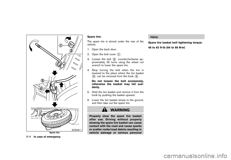
SCE0811
Spare tire
Spare tire:
The spare tire is stored under the rear of the
vehicle.
1. Open the back door.
2. Open the bolt cover
*1.
3. Loosen the bolt
*2
counterclockwise ap-
proximately 25 turns using the wheel nut
wrench to lower the spare tire.
4. Stop turning the bolt when the tire is lowered to the place where the tire basket
*3
can be removed from the hook
*4.
Do not loosen the bolt excessively,
otherwise the basket may fall sud-
denly.
5. Hold the tire basket and remove it from the hook by pushing the basket upward.
6. Lower the tire basket slowly to the ground, and then take out the spare tire.
WARNING
Properly stow the spare tire basket
after use. Driving without properly
stowing the spare tire basket can cause
contact with the road and cause sparks
or scatter rocks/road debris resulting in
vehicle damage or serious personal injury.
Spare tire basket bolt tightening torque:
48 to 63 ft-lb (64 to 86 N·m)
6-4
In case of emergency