tow NISSAN CUBE 2014 3.G User Guide
[x] Cancel search | Manufacturer: NISSAN, Model Year: 2014, Model line: CUBE, Model: NISSAN CUBE 2014 3.GPages: 332, PDF Size: 2.59 MB
Page 92 of 332
Malfunction Indicator Light (MIL)
If the malfunction indicator light illuminates
steady or blinks while the engine is running, it
may indicate a potential emission control and/or
Continuously Variable Transmission (CVT) mal-
function.
The malfunction indicator light may also illumi-
nate steady if the fuel-filler cap is loose or
missing, or if the vehicle runs out of fuel. Check
to make sure the fuel-filler cap is installed and
closed tightly, and that the vehicle has at least 3
US gallons (11.4 liters) of fuel in the fuel tank.
After a few driving trips, the
light should
turn off if no other potential emission control
system malfunction exists.
If this indicator light remains on for 20 seconds
and then blinks for 10 seconds when the engine
is not running, it indicates that the vehicle is not
ready for an emission control system inspection/
maintenance test. (See “Readiness for Inspec-
tion/Maintenance (I/M) test” (P.9-19) .)
Operation:
The malfunction indicator light will illuminate in
one of two ways:
. Malfunction indicator light illuminated steady
— An emission control system and/or CVT
malfunction has been detected. Check the
fuel-filler cap if the LOOSE FUEL CAP warning message is displayed on the twin
trip odometer. If the fuel-filler cap is loose or
missing, tighten or install the cap and
continue to drive the vehicle. The
light
should turn off after a few driving trips. If the
light does not turn off after a few driving
trips, have the vehicle inspected by a
NISSAN dealer. You do not need to have
your vehicle towed to the dealer.
. Malfunction indicator light blinking — An
engine misfire has been detected which may
damage the emission control system.
To reduce or avoid emission control system
damage:
1) Do not drive at speeds above 45 MPH
(72 km/h).
2) Avoid hard acceleration or deceleration.
3) Avoid steep uphill grades.
4) If possible, reduce the amount of cargo being hauled or towed.
The malfunction indicator light may stop
blinking and remain on.
Have the vehicle inspected by a NISSAN
dealer. You do not need to have your vehicle
towed to the dealer.
CAUTION
Continued vehicle operation without
having the emission control system
and/or CVT system checked and re-
paired as necessary could lead to poor
driveability, reduced fuel economy, and
possible damage to the emission con-
trol system.
Overdrive off indicator light (if so
equipped)
The overdrive off indicator light illuminates when
the overdrive off mode is selected.
For additional information, see “Continuously
Variable Transmission (CVT)” (P.5-14) of this
manual.
Security indicator light
The light blinks when the ignition switch is in the
ACC, OFF or LOCK position. This function
indicates the security system equipped on the
vehicle is operational.
If the security system is malfunctioning, this light
will remain on while the ignition switch is in the
ON position. For additional information, see
“Security systems” (P.2-19) .
Instruments and controls2-17
Page 97 of 332
2-22Instruments and controls
WARNING
In freezing temperatures the washer
solution may freeze on the windshield
and obscure your vision which may lead
to an accident. Warm windshield with
the defroster before you wash the
windshield.
CAUTION
.Do not operate the washer continu-
ously for more than 30 seconds.
. Do not operate the washer if the
reservoir tank is empty.
. Do not fill the window washer
reservoir tank with washer fluid
concentrates at full strength. Some
methyl alcohol based washer fluid
concentrates may permanently stain
the grille if spilled while filling the
window washer reservoir tank.
. Pre-mix washer fluid concentrates
with water to the manufacturer’s
recommended levels before pouring
the fluid into the window washer reservoir tank. Do not use the
window washer reservoir tank to
mix the washer fluid concentrate
and water.
If the windshield wiper operation is inter-
rupted by snow or ice, the wiper may stop
moving to protect its motor. If this occurs,
turn the wiper switch to the OFF position
and remove the snow or ice that is on and
around the wiper arms. In approximately 1
minute, turn the switch on again to operate
the wiper.SIC3664
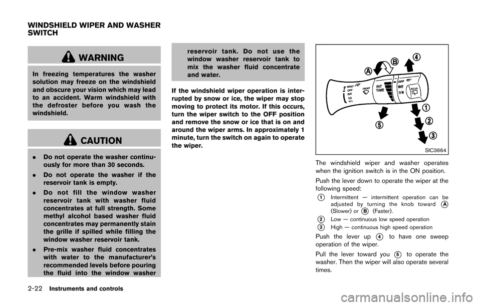
The windshield wiper and washer operates
when the ignition switch is in the ON position.
Push the lever down to operate the wiper at the
following speed:
*1Intermittent — intermittent operation can be
adjusted by turning the knob toward*A(Slower) or*B(Faster) .
*2Low — continuous low speed operation
*3High — continuous high speed operation
Push the lever up*4to have one sweep
operation of the wiper.
Pull the lever toward you
*5to operate the
washer. Then the wiper will also operate several
times.
WINDSHIELD WIPER AND WASHER
SWITCH
Page 101 of 332
2-26Instruments and controls
SIC3670
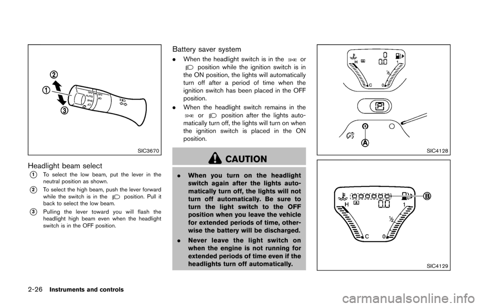
Headlight beam select
*1To select the low beam, put the lever in the
neutral position as shown.
*2To select the high beam, push the lever forward
while the switch is in theposition. Pull it
back to select the low beam.
*3Pulling the lever toward you will flash the
headlight high beam even when the headlight
switch is in the OFF position.
Battery saver system
. When the headlight switch is in theorposition while the ignition switch is in
the ON position, the lights will automatically
turn off after a period of time when the
ignition switch has been placed in the OFF
position.
. When the headlight switch remains in the
orposition after the lights auto-
matically turn off, the lights will turn on when
the ignition switch is placed in the ON
position.
CAUTION
. When you turn on the headlight
switch again after the lights auto-
matically turn off, the lights will not
turn off automatically. Be sure to
turn the light switch to the OFF
position when you leave the vehicle
for extended periods of time, other-
wise the battery will be discharged.
. Never leave the light switch on
when the engine is not running for
extended periods of time even if the
headlights turn off automatically.
SIC4128
SIC4129
Page 123 of 332
3-10Pre-driving checks and adjustments
WARNING
.Radio waves could adversely affect
electric medical equipment. Those
who use a pacemaker should con-
tact the electric medical equipment
manufacturer for the possible influ-
ences before use.
. The Intelligent Key transmits radio
waves when the buttons are
pushed. The FAA advises that the
radio waves may affect aircraft na-
vigation and communication sys-
tems. Do not operate the
Intelligent Key while on an airplane.
Make sure the buttons are not
operated unintentionally when the
unit is stored during a flight.
The Intelligent Key system can operate all the
door locks using the remote controller function
or pushing the request switch on the vehicle
without taking the key out from a pocket or
purse. The operating environment and/or condi-
tions may affect the Intelligent Key system
operation.
Be sure to read the following before using the
Intelligent Key system.
CAUTION
. Be sure to carry the Intelligent Key
with you when operating the vehi-
cle.
. Never leave the Intelligent Key in
the vehicle when you leave the
vehicle.
The Intelligent Key is always communicating with
the vehicle as it receives radio waves. The
Intelligent Key system transmits weak radio
waves. Environmental conditions may interfere
with the operation of the Intelligent Key system
under the following operating conditions.
. When operating near a location where
strong radio waves are transmitted, such
as a TV tower, power station and broad-
casting station.
. When in possession of wireless equipment,
such as a cellular phone, transceiver, and
CB radio.
. When the Intelligent Key is in contact with or
covered by metallic materials.
. When any type of radio wave remote control
is used nearby.
. When the Intelligent Key is placed near an
electric appliance such as a personal computer.
. When the vehicle is parked near a parking
meter.
In such cases, correct the operating conditions
before using the Intelligent Key function or use
the mechanical key.
Although the life of the battery varies depending
on the operating conditions, the battery’s life is
approximately 2 years. If the battery is dis-
charged, replace it with a new one.
Since the Intelligent Key is continuously receiv-
ing radio waves, if the key is left near equipment
which transmits strong radio waves, such as
signals from a TV and personal computer, the
battery life may become shorter.
For information regarding replacement of a
battery, see “Key battery replacement” (P.8-23) .
As many as 4 Intelligent Keys can be registered
and used with one vehicle. For information about
the purchase and use of additional Intelligent
Keys, contact a NISSAN dealer.
CAUTION
. Do not allow the Intelligent Key,
which contains electrical compo-
nents, to come into contact with
water or salt water. This could affect
INTELLIGENT KEY SYSTEM (if so
equipped)
Page 138 of 332
SPA2214
OUTSIDE MIRRORS
WARNING
Objects viewed in the outside mirror on
the passenger side are closer than they
appear. Be careful when moving to the
right. Using only this mirror could cause
an accident. Use the inside mirror or
glance over your shoulder to properly
judge distances to other objects.
Adjusting outside mirrors
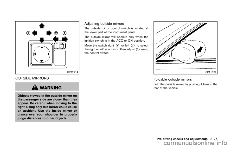
The outside mirror control switch is located at
the lower part of the instrument panel.
The outside mirror will operate only when the
ignition switch is in the ACC or ON position.
Move the switch right
*1or left*2to select
the right or left side mirror, then adjust
*3using
the control switch.
SPA1829
Foldable outside mirrors
Fold the outside mirror by pushing it toward the
rear of the vehicle.
Pre-driving checks and adjustments3-25
Page 145 of 332
4-4Center display, heater, air conditioner, audio and phone systems
.To clean the display, never use a
rough cloth, alcohol, benzine, thin-
ner or any kind of solvent or paper
towel with a chemical cleaning
agent. They will scratch or deterio-
rate the panel.
. Do not splash any liquid such as
water or car fragrance on the dis-
play. Contact with liquid will cause
the system to malfunction.
To help ensure safe driving, some functions
cannot be operated while driving.
The on-screen functions that are not available
while driving will be “grayed out” or muted.
Park the vehicle in a safe location and then
operate the navigation system.
SAA3422
Touch screen operation
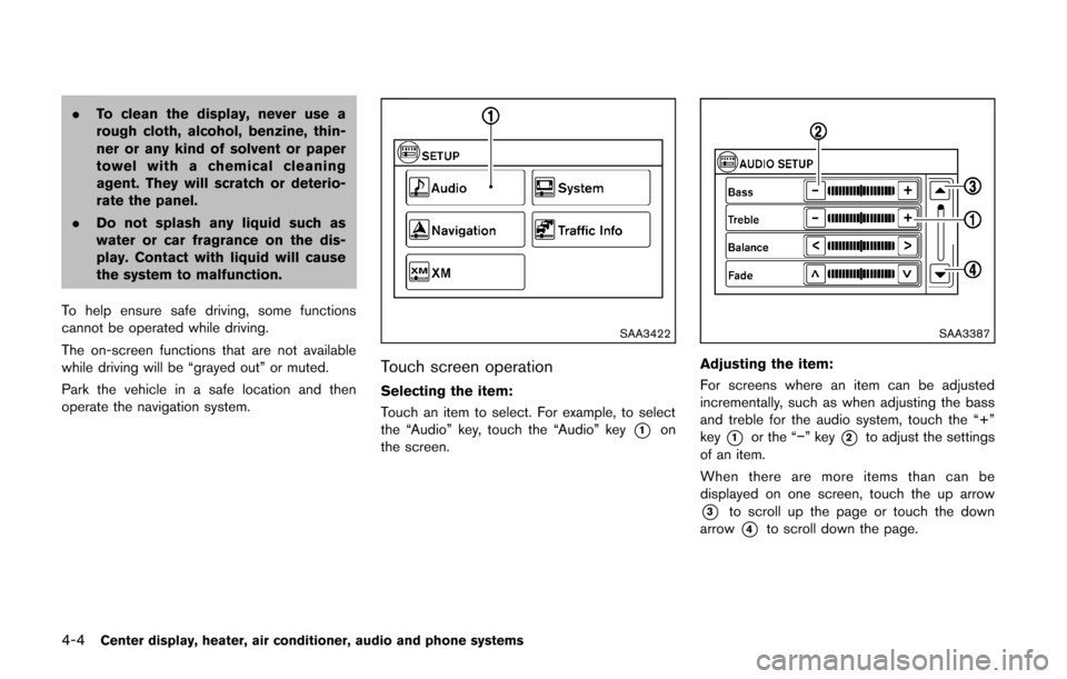
Selecting the item:
Touch an item to select. For example, to select
the “Audio” key, touch the “Audio” key
*1on
the screen.
SAA3387
Adjusting the item:
For screens where an item can be adjusted
incrementally, such as when adjusting the bass
and treble for the audio system, touch the “+”
key
*1or the “−” key*2to adjust the settings
of an item.
When there are more items than can be
displayed on one screen, touch the up arrow
*3to scroll up the page or touch the down
arrow
*4to scroll down the page.
Page 208 of 332
THREE-WAY CATALYST
The three-way catalyst is an emission control
device installed in the exhaust system. Exhaust
gases in the three-way catalyst are burned at
high temperatures to help reduce pollutants.
WARNING
.The exhaust gas and the exhaust
system are very hot. Keep people,
animals or flammable materials
away from the exhaust system com-
ponents.
. Do not stop or park the vehicle over
flammable materials such as dry
grass, waste paper or rags. They
may ignite and cause a fire.
CAUTION
.Do not use leaded gasoline. Depos-
its from leaded gasoline will ser-
iously reduce the three-way
catalyst’s ability to help reduce ex-
haust pollutants.
. Keep your engine tuned up. Mal-
functions in the ignition, fuel injec- tion, or electrical systems can cause
overrich fuel flow into the three-way
catalyst, causing it to overheat. Do
not keep driving if the engine mis-
fires, or if noticeable loss of perfor-
mance or other unusual operating
conditions are detected. Have the
vehicle inspected promptly by a
NISSAN dealer.
. Avoid driving with an extremely low
fuel level. Running out of fuel could
cause the engine to misfire, dama-
ging the three-way catalyst.
. Do not race the engine while warm-
ing it up.
. Do not push or tow your vehicle to
start the engine.
TIRE PRESSURE MONITORING SYS-
TEM (TPMS)
Each tire, including the spare (if provided) ,
should be checked monthly when cold and
inflated to the inflation pressure recommended
by the vehicle manufacturer on the vehicle
placard or tire inflation pressure label. (If your
vehicle has tires of a different size than the size
indicated on the vehicle placard or tire inflation
pressure label, you should determine the proper
tire inflation pressure for those tires.)
As an added safety feature, your vehicle has
been equipped with a Tire Pressure Monitoring
System (TPMS) that illuminates a low tire
pressure telltale when one or more of your tires
is significantly under-inflated. Accordingly, when
the low tire pressure telltale illuminates, you
should stop and check your tires as soon as
possible, and inflate them to the proper pres-
sure. Driving on a significantly under-inflated tire
causes the tire to overheat and can lead to tire
failure. Under-inflation also reduces fuel effi-
ciency and tire tread life, and may affect the
vehicle’s handling and stopping ability.
Please note that the TPMS is not a substitute for
proper tire maintenance, and it is the driver’s
responsibility to maintain correct tire pressure,
even if under-inflation has not reached the level
to trigger illumination of the TPMS low tire
Starting and driving5-3
Page 215 of 332
5-10Starting and driving
.The cargo room area is not included in the
operating range but the Intelligent Key may
function.
. If the Intelligent Key is placed on the
instrument panel, inside the glove box or
door pocket, the Intelligent Key may not
function.
. If the Intelligent Key is placed near the door
or window outside the vehicle, the Intelligent
Key may function.
SSD0859
PUSH-BUTTON IGNITION SWITCH
OPERATION
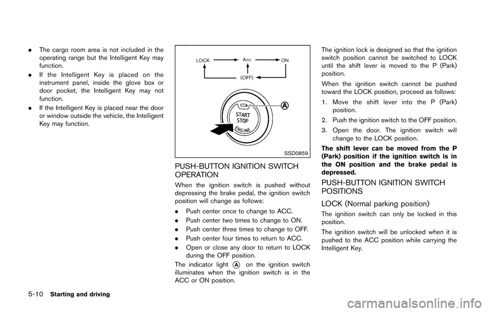
When the ignition switch is pushed without
depressing the brake pedal, the ignition switch
position will change as follows:
.Push center once to change to ACC.
. Push center two times to change to ON.
. Push center three times to change to OFF.
. Push center four times to return to ACC.
. Open or close any door to return to LOCK
during the OFF position.
The indicator light
*Aon the ignition switch
illuminates when the ignition switch is in the
ACC or ON position. The ignition lock is designed so that the ignition
switch position cannot be switched to LOCK
until the shift lever is moved to the P (Park)
position.
When the ignition switch cannot be pushed
toward the LOCK position, proceed as follows:
1. Move the shift lever into the P (Park)
position.
2. Push the ignition switch to the OFF position.
3. Open the door. The ignition switch will change to the LOCK position.
The shift lever can be moved from the P
(Park) position if the ignition switch is in
the ON position and the brake pedal is
depressed.
PUSH-BUTTON IGNITION SWITCH
POSITIONS
LOCK (Normal parking position)
The ignition switch can only be locked in this
position.
The ignition switch will be unlocked when it is
pushed to the ACC position while carrying the
Intelligent Key.
Page 230 of 332
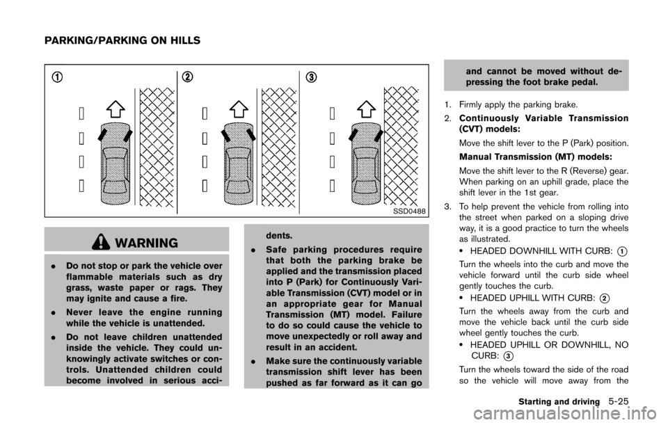
SSD0488
WARNING
.Do not stop or park the vehicle over
flammable materials such as dry
grass, waste paper or rags. They
may ignite and cause a fire.
. Never leave the engine running
while the vehicle is unattended.
. Do not leave children unattended
inside the vehicle. They could un-
knowingly activate switches or con-
trols. Unattended children could
become involved in serious acci- dents.
. Safe parking procedures require
that both the parking brake be
applied and the transmission placed
into P (Park) for Continuously Vari-
able Transmission (CVT) model or in
an appropriate gear for Manual
Transmission (MT) model. Failure
to do so could cause the vehicle to
move unexpectedly or roll away and
result in an accident.
. Make sure the continuously variable
transmission shift lever has been
pushed as far forward as it can go and cannot be moved without de-
pressing the foot brake pedal.
1. Firmly apply the parking brake.
2. Continuously Variable Transmission
(CVT) models:
Move the shift lever to the P (Park) position.
Manual Transmission (MT) models:
Move the shift lever to the R (Reverse) gear.
When parking on an uphill grade, place the
shift lever in the 1st gear.
3. To help prevent the vehicle from rolling into the street when parked on a sloping drive
way, it is a good practice to turn the wheels
as illustrated.
.HEADED DOWNHILL WITH CURB:*1
Turn the wheels into the curb and move the
vehicle forward until the curb side wheel
gently touches the curb.
.HEADED UPHILL WITH CURB:*2
Turn the wheels away from the curb and
move the vehicle back until the curb side
wheel gently touches the curb.
.HEADED UPHILL OR DOWNHILL, NOCURB:
*3
Turn the wheels toward the side of the road
so the vehicle will move away from the
Starting and driving5-25
PARKING/PARKING ON HILLS
Page 238 of 332
6 In case of emergency
Hazard warning flasher switch .............................................. 6-2
Emergency engine shut off (models with Intelligent
Key system) ........................................................................\
........ 6-2
Flat tire ........................................................................\
................. 6-3 Tire Pressure Monitoring System (TPMS) .................... 6-3
Changing a flat tire ............................................................. 6-3 Jump starting ........................................................................\
.. 6-10
Push starting ........................................................................\
... 6-12
If your vehicle overheats ...................................................... 6-12
Towing your vehicle .............................................................. 6-14
Towing recommended by NISSAN ........................... 6-15
Vehicle recovery (freeing a stuck vehicle) ............... 6-16