clock NISSAN FRONTIER 2002 D22 / 1.G User Guide
[x] Cancel search | Manufacturer: NISSAN, Model Year: 2002, Model line: FRONTIER, Model: NISSAN FRONTIER 2002 D22 / 1.GPages: 273, PDF Size: 2.25 MB
Page 127 of 273

All Preset Scan
Pressing the Preset Scan button (>1.5 sec-
onds) scans all the permanent preset
memory banks (A, B or C) from 1-6 for 5
seconds. If the Travel Preset is ON, all the
travel preset memory banks (A, B, or C)
from 1-6 are scanned for 5 seconds.
Canceling preset scan mode
Pressing any button except CLOCK, EJECT
and PTY cancels the Preset Scan mode.
RDS (Radio Data System)
RDS stands for Radio Data System, and is
a data information service transmitted by
some radio stations on the FM band (not
AM band) encoded within a regular radio
broadcast. Currently, most RDS stations
are in large cities, but many stations are
now considering broadcasting RDS data.
RDS can display:
cStation call sign, such as ªWHFR 98.3º.
cStation name, such as ªThe Grooveº.
cMusic or programming type such as
ªClassicalº, ªCountryº, or ªRockº.
cTraffic reports about delays or construc-
tion.
If the station broadcasts RDS information,
the RDS icon is displayed. The RDS infor-
mation will be displayed according to the
option chosen in the RDS setup mode. (FM
& RDS is the default.) Press the RDS button
again to display the frequency for 3 sec-
onds. The radio will then return to the nor-
mal display. If the station does not broad-
cast RDS information, the RDS icon will not
be displayed.Setting RDS Mode
Press the RDS button (>3 seconds) until the
display showsªRDS SET MODEº. This
display will last 2 seconds and then change
toªTRAFFIC-OFFº. Press TUNE/FF-REV
(
or) to toggle the RDS traffic mode
from ªOFFº to ªONº. Press the RDS button
again to set your traffic mode selection.
The display changes toªSHOWºfor the
second part of the RDS mode selection.
Press TUNE/FF-REV (
or) to switch
between the following RDS display modes:
cªFM & RDSº: the radio display will show
the station's broadcast frequency and the
station's name.
cªRDS ONLYº: the radio display will show
the station's name only.
cªRDS TEMPº: the radio display will show
the station's name for 5 seconds and
then display only the radio station's
broadcast frequency.
PTY (Program Type)
PTY can be used to search for a certain
program type. Certain areas have a limited
number of stations that transmit RDS. Many
stations transmit call letters and frequencies
LHA0086
4-24Heater, air conditioner and audio systems
ZX
Page 134 of 273

STEERING WHEEL SWITCH FOR
AUDIO CONTROLS
The steering wheel switch for audio controls
is mounted on the left side of the steering
wheel.
Press the MODE button to turn the radio on
or, if the radio is already on, to switch
between the Radio presets (A, B or C) and
CD Mode.
A!B!C!CD MODE
The last CD that was loaded starts to play
when in CD Mode. If there is no CD loaded,the CD changer enters Disc Loading Mode.
If in Radio presets A, B or C:
cPressor(<1.5 seconds) to
advance to the next preset station or to
return to the previous preset station.
cHold down
or(>1.5 seconds).
The radio will seek up or down to the next
radio station.
If in CD Mode:
cPress
or(<1.5 seconds) to
advance to the next selection on the CDor return to the previous selection on the
CD.
cHold down
or(>1.5 seconds)
to advance to the next CD or to return to
the previous CD.
Volume control is located on the side of the
audio control switch. Press the top of the
volume control to increase volume. Press
the bottom of the volume control to de-
crease volume.
ANTENNA
The antenna cannot be shortened, but it can
be removed. When you need to remove the
antenna, turn the antenna rod counterclock-
wise.
To install the antenna rod, turn the antenna
clockwise. Tighten the antenna rod to speci-
fication using a suitable tool such as a
open-end wrench. The antenna rod tighten-
ing specification is 3.4 - 3.6 Nzm(30-32
in-lb). Do not use pliers to tighten the an-
tenna as they can leave marks on the
antenna surface. The antenna rod can not
be hand tightened to the proper specifica-
tion.WHA0128
Heater, air conditioner and audio systems4-31
ZX
Page 143 of 273

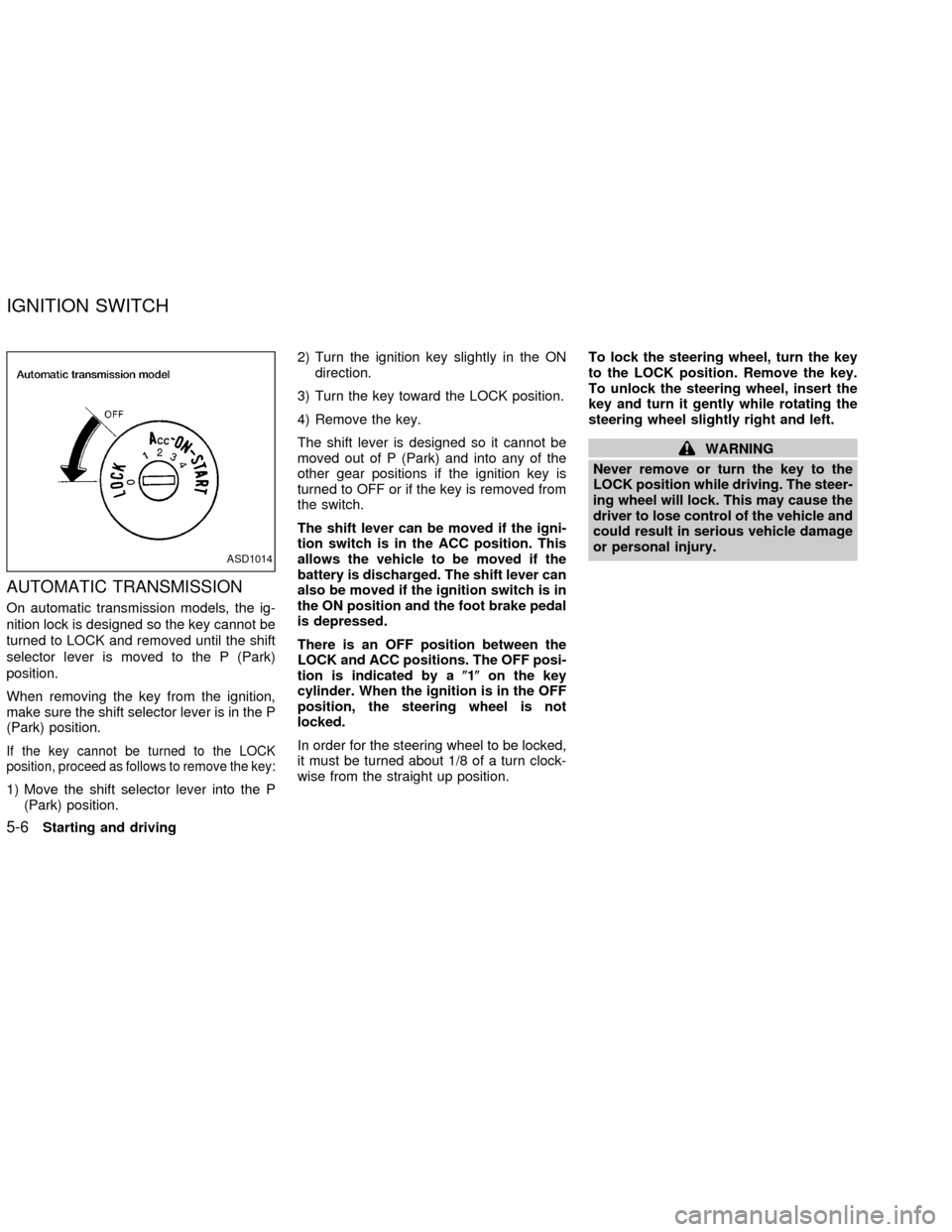
AUTOMATIC TRANSMISSION
On automatic transmission models, the ig-
nition lock is designed so the key cannot be
turned to LOCK and removed until the shift
selector lever is moved to the P (Park)
position.
When removing the key from the ignition,
make sure the shift selector lever is in the P
(Park) position.
If the key cannot be turned to the LOCK
position, proceed as follows to remove the key:
1) Move the shift selector lever into the P
(Park) position.2) Turn the ignition key slightly in the ON
direction.
3) Turn the key toward the LOCK position.
4) Remove the key.
The shift lever is designed so it cannot be
moved out of P (Park) and into any of the
other gear positions if the ignition key is
turned to OFF or if the key is removed from
the switch.
The shift lever can be moved if the igni-
tion switch is in the ACC position. This
allows the vehicle to be moved if the
battery is discharged. The shift lever can
also be moved if the ignition switch is in
the ON position and the foot brake pedal
is depressed.
There is an OFF position between the
LOCK and ACC positions. The OFF posi-
tion is indicated by a(1(on the key
cylinder. When the ignition is in the OFF
position, the steering wheel is not
locked.
In order for the steering wheel to be locked,
it must be turned about 1/8 of a turn clock-
wise from the straight up position.To lock the steering wheel, turn the key
to the LOCK position. Remove the key.
To unlock the steering wheel, insert the
key and turn it gently while rotating the
steering wheel slightly right and left.
WARNING
Never remove or turn the key to the
LOCK position while driving. The steer-
ing wheel will lock. This may cause the
driver to lose control of the vehicle and
could result in serious vehicle damage
or personal injury.
ASD1014
IGNITION SWITCH
5-6Starting and driving
ZX
Page 144 of 273

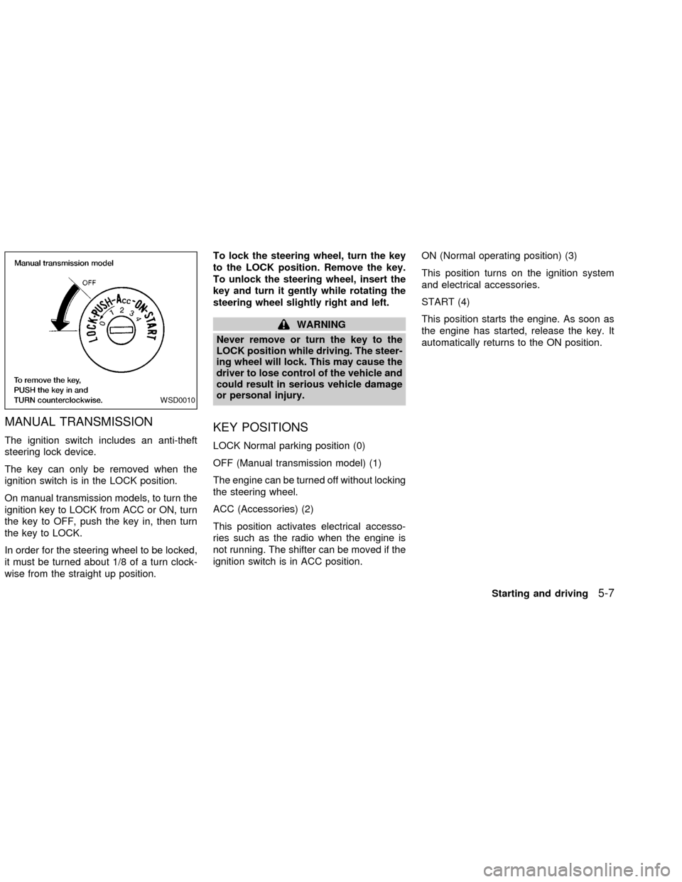
MANUAL TRANSMISSION
The ignition switch includes an anti-theft
steering lock device.
The key can only be removed when the
ignition switch is in the LOCK position.
On manual transmission models, to turn the
ignition key to LOCK from ACC or ON, turn
the key to OFF, push the key in, then turn
the key to LOCK.
In order for the steering wheel to be locked,
it must be turned about 1/8 of a turn clock-
wise from the straight up position.To lock the steering wheel, turn the key
to the LOCK position. Remove the key.
To unlock the steering wheel, insert the
key and turn it gently while rotating the
steering wheel slightly right and left.
WARNING
Never remove or turn the key to the
LOCK position while driving. The steer-
ing wheel will lock. This may cause the
driver to lose control of the vehicle and
could result in serious vehicle damage
or personal injury.
KEY POSITIONS
LOCK Normal parking position (0)
OFF (Manual transmission model) (1)
The engine can be turned off without locking
the steering wheel.
ACC (Accessories) (2)
This position activates electrical accesso-
ries such as the radio when the engine is
not running. The shifter can be moved if the
ignition switch is in ACC position.ON (Normal operating position) (3)
This position turns on the ignition system
and electrical accessories.
START (4)
This position starts the engine. As soon as
the engine has started, release the key. It
automatically returns to the ON position.
WSD0010
Starting and driving5-7
ZX
Page 145 of 273

cMake sure the area around the vehicle is
clear.
cCheck fluid levels such as engine oil,
coolant, brake and clutch fluid, and win-
dow washer fluid as frequently as pos-
sible, at least whenever you refuel.
cCheck that all windows and lights are
clean.
cVisually inspect tires for their appearance
and condition. Also check tires for proper
inflation.
cLock all doors.
cPosition seat and adjust head restraints.
cAdjust inside and outside mirrors.
cFasten seat belts and ask all passengers
to do likewise.
cCheck the operation of warning lights
when key is turned to the ON (3) position.
See9Warning/Indicator lights and au-
dible reminders9in the9Instruments and
controls9section.1. Apply the parking brake.
2.Automatic transmission:
Move the selector lever to P (Park) or N
(Neutral). P (Park) is preferred.
The selector lever cannot be moved
out of P (Park) and into any of the
other gear positions if the ignition key
is turned to OFF or if the key is re-
moved from the ignition switch.
The starter is designed not to operate
if the selector lever is in one of the
driving positions.
Manual transmission:
Move the shift lever to N (Neutral), and
fully depress the clutch pedal to the floor
while starting the engine.
The starter is designed not to operate
unless the clutch pedal is fully de-
pressed.
3.With your foot off the accelerator
pedal,turn the ignition key to START.
Release the key when the engine starts.
If the engine starts, but fails to run, repeat
the above procedure.cIf the engine is very hard to start in
extremely cold or hot weather, depress
the accelerator pedal fully and hold it
to help start the engine.
cIn the summer, when restarting the
engine within 30 minutes after it has
been stopped, keep the accelerator
pedal fully depressed while starting.
CAUTION
Do not operate the starter for more than
15 seconds at a time. If the engine does
not start, turn the key off and wait 10
seconds before cranking again, other-
wise the starter could be damaged.
4.Warm-up
Always allow the engine to idle for at
least 30 seconds after starting. Drive at a
moderate speed for a short distance first,
especially in cold weather.
BEFORE STARTING THE
ENGINESTARTING THE ENGINE
5-8Starting and driving
ZX
Page 147 of 273

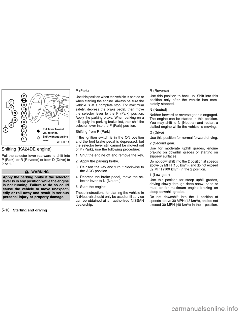
Shifting (KA24DE engine)
Pull the selector lever rearward to shift into
P (Park), or R (Reverse) or from D (Drive) to
2or1.
WARNING
Apply the parking brake if the selector
lever is in any position while the engine
is not running. Failure to do so could
cause the vehicle to move unexpect-
edly or roll away and result in serious
personal injury or property damage.P (Park)
Use this position when the vehicle is parked or
when starting the engine. Always be sure the
vehicle is at a complete stop. For maximum
safety, depress the brake pedal, then move
the selector lever to the P (Park) position.
Apply the parking brake. When parking on a
hill, apply the parking brake first, then shift the
selector lever into the P (Park) position.
Shifting from P (Park)
If the ignition switch is in the ON position
and the foot brake pedal is depressed, but
the selector lever still cannot be moved out
of P (Park), use the following procedure:
1. Shut the engine off and remove the key.
2. Apply the parking brake.
3. Reinsert the key and turn it clockwise to
the ACC position.
4. Depress the brake pedal, move the se-
lector lever to N (Neutral).
5. Start the engine.
These instructions for starting the vehicle in
N (Neutral) should only be used until service
can be obtained at an authorized NISSAN
dealership.R (Reverse)
Use this position to back up. Shift into this
position only after the vehicle has com-
pletely stopped.
N (Neutral)
Neither forward or reverse gear is engaged.
The engine can be started in this position.
You may shift to N (Neutral) and restart a
stalled engine while the vehicle is moving.
D (Drive)
Use this position for normal forward driving.
2 (Second gear)
Use for moderate uphill grades, engine
braking on downhill grades or starting on
slippery surfaces.
Do not downshift into the 2 position at speeds
above 62 MPH (100 km/h), and do not exceed
62 MPH (100 km/h) in the 2 position.
1 (Low gear)
Use this position for steep uphill grades,
driving slowly through deep snow, sand or
mud, or for maximum engine braking on
steep downhill grades.
Do not downshift into the 1 position at
speeds above 30 MPH (48 km/h), and do not
exceed 30 MPH (48 km/h) in the 1 position.
WSD0011
5-10Starting and driving
ZX
Page 170 of 273

For King Cab models:
a. Move the driver's seatback fully forward.
b. Remove the jack and wheel nut wrench
from the tool case located behind the
driver's seat and below the jump seat.
c. Remove the jack rod located behind the
driver's seat.For Crew Cab models:
a. Tilt the rear bench seat forward
b. Remove the jack, jack rod, and tool case
located behind the rear bench seat.
2. Fit the square end of the jack rod into the
square hole of the wheel nut wrench to
form a handle.
3. Find the oval-shaped opening under the
middle of the tailgate. Pass the T-shaped
end of the jack rod through the opening
and direct it towards the spare tire winch,
located directly above the spare tire.4. Seat the T-shaped end of the jack rod
into the T-shaped opening of the spare
tire winch. Apply pressure to keep the
jack rod engaged in the spare tire winch
and turn the jack rod counterclockwise to
lower the spare tire.
ACE1017ACE1039
WCE0013
In case of emergency6-3
ZX
Page 221 of 273

cAiming is not necessary after replac-
ing the bulb. When aiming adjust-
ment is necessary, contact an autho-
rized NISSAN dealer.
cDo not leave the bulb out of the
headlight reflector for a long period
of time as dust, moisture, and smoke
may enter the headlight body and
affect the performance of the head-
light.
Replacing the headlight bulb
1. Open the hood.
2. Disconnect the negative (2) battery
cable.
3 Disconnect the electrical connector from
the rear end of the bulb.
4. Turn the bulb retaining ring counterclock-
wise until it is free from the headlamp
reflector and then remove it.
5. Carefully remove the headlight bulb. Do
not shake or rotate the bulb when remov-
ing it.
DO NOT TOUCH THE BULB.6. Install the new bulb in the reverse order
of removal.
cBe sure the lip of the bulb socket
contacts the headlight body.
Adjusting the headlight aim
Before performing aiming adjustment, make
sure of the following:
a. Use an aiming wall screen.
b. Keep all of the tires inflated to the correct
pressure.
c. Place the vehicle and screen on level
ground.
d. See that the vehicle is unloaded (except
for full levels of coolant, engine oil and
fuel, and that the spare tire, jack, and
tools are stored). Have the driver or an
equivalent weight placed in the driver's
seat.
1. Open the hood. Turn headlight low beam
on.
2. Adjust the vertical aim by turning the
adjustment screw.cCover the opposite headlight and ensure
the fog lights (if so equipped) are turned
off.
cAdjust beam pattern until cutoff line is
positioned at the same height off ground
as bulb center (on H-line).
8-32Maintenance and do-it-yourself
ZX
Page 224 of 273

1. Remove screw.
2. Disconnect connector.
3. Push the fog light assembly towards the
front of the vehicle and pull out to expose
the rear of the assembly.
4. Rotate the bulb cover counterclockwise
and remove.
5. Lift the spring retainer.
6. Remove the fog light bulb from housing.
7. Disconnect the electrical connector.
8. Install the new bulb in the reverse order
of removal. DO NOT TOUCH THE
BULB.EXTERIOR AND INTERIOR LIGHTS
Item Wattage (W) Bulb No.*
Front combination light:
Headlight 55/65 9007
Turn signal light 28.5 3456k
Parking light side front 5 168
Side marker 5 168
Rear combination light:
Turn signal 27 3157NA
Stop/Tail 27/7 3157k
Back-up 27 3156k
License plate light 3.8 168
Fog light 55 H3
Dome light type A Ð 83
Dome light type B Ð Ð
Dome light type C Ð Ð
Cargo light 10 Ð
Map light 8 578
High-mounted stop lightSee an authorized NISSAN
dealer for assistance.
*: Always check with the Parts Department at an authorized NISSAN dealer for the latest parts
information.
Maintenance and do-it-yourself8-35
ZX