roof NISSAN FRONTIER 2002 D22 / 1.G Owners Manual
[x] Cancel search | Manufacturer: NISSAN, Model Year: 2002, Model line: FRONTIER, Model: NISSAN FRONTIER 2002 D22 / 1.GPages: 273, PDF Size: 2.25 MB
Page 51 of 273

2 Instruments and controls
Instrument panel ....................................................2-2
Meters and gauges ................................................2-3
Speedometer and odometer .............................2-3
Tachometer........................................................2-5
Engine coolant temperature gauge ...................2-5
Fuel gauge ........................................................2-6
Compass and outside temperature display
(if so equipped) ......................................................2-6
Outside temperature display .............................2-7
Compass display ...............................................2-7
Warning/indicator lights and audible
reminders..............................................................2-10
Checking bulbs ................................................2-10
Warning lights ..................................................2-11
Indicator lights .................................................2-14
Audible reminders............................................2-15
Security system ..................................................2-15
Vehicle security system (if so equipped) ........2-15
Windshield wiper and washer switch ...................2-18
Switch operation ..............................................2-19
Rear window defogger switch (Crew Cab
models only) .........................................................2-19Headlight and turn signal switch ..........................2-20
Headlight switch ..............................................2-20
Turn signal switch............................................2-21
Front fog light switch (if so equipped)..................2-21
Hazard warning flasher switch .............................2-22
Horn ......................................................................2-22
Power point (if so equipped) ................................2-23
Cigarette lighter and ash tray (accessories) ........2-24
Storage .................................................................2-24
Storage compartment ......................................2-24
Cup holders (if so equipped) ...........................2-25
Glove box ........................................................2-26
Console box ....................................................2-26
Grocery hooks (King Cab only) .......................2-27
Windows ...............................................................2-27
Power windows (if so equipped) .....................2-27
Manual windows ..............................................2-29
Rear sliding window (if so equipped) ..............2-29
Sunroof (if so equipped).......................................2-30
Tilting the sunroof ............................................2-30
Removing/installing..........................................2-31
Interior lights .........................................................2-33
ZX
Page 81 of 273
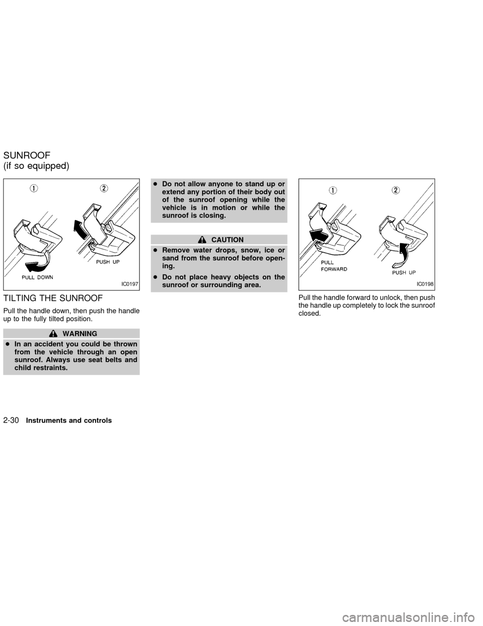
TILTING THE SUNROOF
Pull the handle down, then push the handle
up to the fully tilted position.
WARNING
cIn an accident you could be thrown
from the vehicle through an open
sunroof. Always use seat belts and
child restraints.cDo not allow anyone to stand up or
extend any portion of their body out
of the sunroof opening while the
vehicle is in motion or while the
sunroof is closing.
CAUTION
cRemove water drops, snow, ice or
sand from the sunroof before open-
ing.
cDo not place heavy objects on the
sunroof or surrounding area.
Pull the handle forward to unlock, then push
the handle up completely to lock the sunroof
closed.
IC0197IC0198
SUNROOF
(if so equipped)
2-30Instruments and controls
ZX
Page 82 of 273
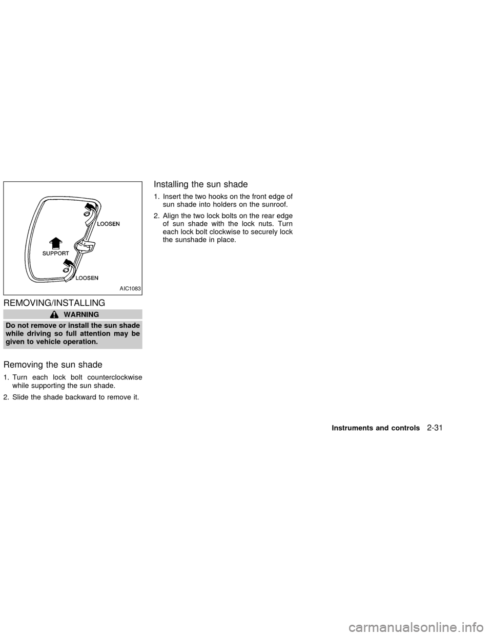
REMOVING/INSTALLING
WARNING
Do not remove or install the sun shade
while driving so full attention may be
given to vehicle operation.
Removing the sun shade
1. Turn each lock bolt counterclockwise
while supporting the sun shade.
2. Slide the shade backward to remove it.
Installing the sun shade
1. Insert the two hooks on the front edge of
sun shade into holders on the sunroof.
2. Align the two lock bolts on the rear edge
of sun shade with the lock nuts. Turn
each lock bolt clockwise to securely lock
the sunshade in place.
AIC1083
Instruments and controls2-31
ZX
Page 83 of 273
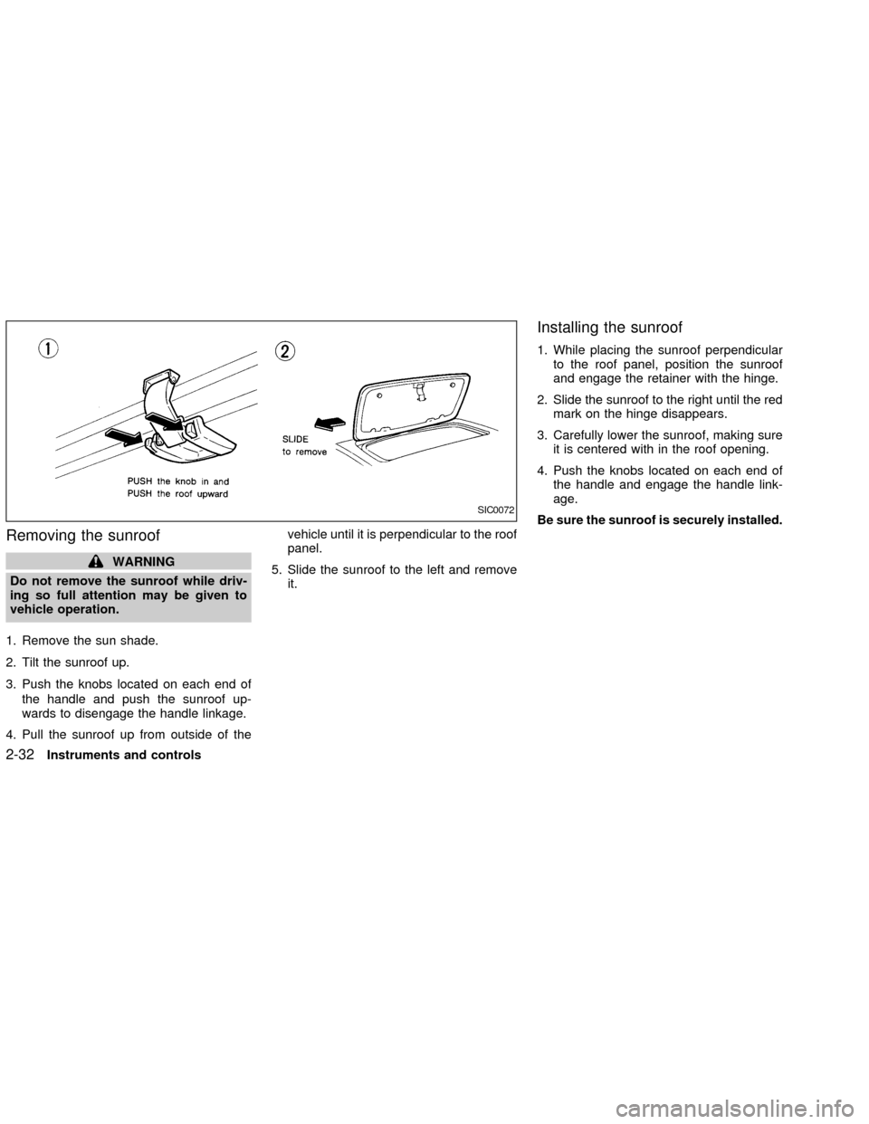
Removing the sunroof
WARNING
Do not remove the sunroof while driv-
ing so full attention may be given to
vehicle operation.
1. Remove the sun shade.
2. Tilt the sunroof up.
3. Push the knobs located on each end of
the handle and push the sunroof up-
wards to disengage the handle linkage.
4. Pull the sunroof up from outside of thevehicle until it is perpendicular to the roof
panel.
5. Slide the sunroof to the left and remove
it.
Installing the sunroof
1. While placing the sunroof perpendicular
to the roof panel, position the sunroof
and engage the retainer with the hinge.
2. Slide the sunroof to the right until the red
mark on the hinge disappears.
3. Carefully lower the sunroof, making sure
it is centered with in the roof opening.
4. Push the knobs located on each end of
the handle and engage the handle link-
age.
Be sure the sunroof is securely installed.
SIC0072
2-32Instruments and controls
ZX
Page 86 of 273

3 Pre-driving checks and adjustments
Key .........................................................................3-2
Doors ......................................................................3-2
Locking with key ................................................3-2
Locking with inside lock knob............................3-3
Locking with power door lock switch.................3-3
Child safety rear door lock
(Crew Cab models only)....................................3-4
Remote keyless entry system (if so equipped)......3-4
How to use remote keyless entry
system ...............................................................3-4
Battery replacement ..........................................3-7
Hood .......................................................................3-8
Roof rack (if so equipped)......................................3-9
Step rail (if so equipped) ......................................3-11
Fuel filler lid ..........................................................3-11Fuel filler cap ...................................................3-11
Steering wheel .....................................................3-12
Tilt operation (if so equipped) .........................3-12
Sun visors.............................................................3-13
Vanity mirror (if so equipped) ..........................3-13
Mirrors ..................................................................3-13
Inside mirror.....................................................3-13
Outside mirrors ................................................3-13
Outside mirror remote control
(if so equipped)................................................3-14
Truck box..............................................................3-15
Tailgate ............................................................3-15
Tie down hooks ...............................................3-17
ZX
Page 94 of 273
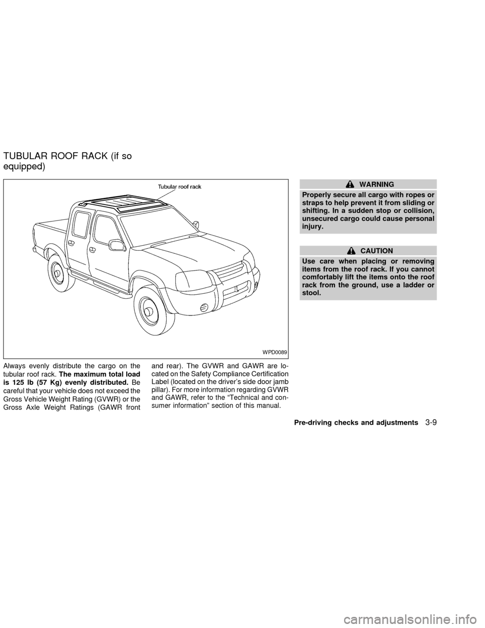
Always evenly distribute the cargo on the
tubular roof rack.The maximum total load
is 125 lb (57 Kg) evenly distributed.Be
careful that your vehicle does not exceed the
Gross Vehicle Weight Rating (GVWR) or the
Gross Axle Weight Ratings (GAWR frontand rear). The GVWR and GAWR are lo-
cated on the Safety Compliance Certification
Label (located on the driver's side door jamb
pillar). For more information regarding GVWR
and GAWR, refer to the ªTechnical and con-
sumer informationº section of this manual.
WARNING
Properly secure all cargo with ropes or
straps to help prevent it from sliding or
shifting. In a sudden stop or collision,
unsecured cargo could cause personal
injury.
CAUTION
Use care when placing or removing
items from the roof rack. If you cannot
comfortably lift the items onto the roof
rack from the ground, use a ladder or
stool.
WPD0089
TUBULAR ROOF RACK (if so
equipped)
Pre-driving checks and adjustments3-9
ZX
Page 95 of 273

The front and rear crossbars can be ad-
justed forward, backward, or be removed.
Use the torxdriver located in the tool kit to
loosen both crossbar adjusting screws. Po-
sition the crossbar as needed and then
tighten the crossbar adjusting screws. Placeyour cargo between the bars, and secure
with rope. Always check the tightness of the
cross bar adjusting screws.
If you hear windnoise coming from the roof
rack while driving, adjust the roof rack
crossbars to the most rearward position.
AIC1147
3-10Pre-driving checks and adjustments
ZX
Page 109 of 273

the on position. Be sure to return the air
recirculation button to the off position for
normal cooling.
Dehumidfied heating
This mode is used to heat and dehumidfy
the air.
1. Push the
button to the off position.
2. Turn the air control dial to the
posi-
tion.
3. Turn the fan control dial to the desired
position.
4. Turn on the air conditioner button. The
indicator light comes on.
5. Turn the temperature control dial to the
desired position.
Dehumidfied defrosting/defogging
This mode is used to defog the windows
and dehumidify the air.
1. Turn the air control dial to the
posi-
tion.
cWhen the
,or positions in be-
tween are selected, the air conditioner
automatically turns on (however, the in-
dicator light will not illuminate) if theoutside temperature is more than 45ÉF
(7ÉC). This dehumidifies the air which
helps defog the windshield. The
mode automatically turns off, al-
lowing outside air to be drawn into the
passenger compartment to further im-
prove the defogging performance.
2. Turn the fan control dial to the desired
position.
3. Turn the temperature control dial to the
desired position.
Operating tips
cKeep windows and sunroof closed while
the air conditioner is in operation.
cAfter parking in the sun, drive for two or
three minutes with the windows open to
vent hot air from the passenger compart-
ment. Then, close the windows. This
allows the air conditioner to cool the
interior more quickly.
cThe air conditioning system should be
operated for approximately ten min-
utes at least once a month. This helps
prevent damage to the system due to
lack of lubrication.
cIf the engine coolant temperaturegauge indicates engine coolant tem-
perature over the normal range, turn
the air conditioner off. See(If your
vehicle overheats(in the(In case of
emergency(section of this manual.
AIR FLOW CHARTS
The following charts show the button and
dial positions forMAXIMUM AND QUICK
heating, cooling or defrosting.The air recir-
culation switch should always be in the
OFF position for heating and defrosting.
When the
,or positions in be-
tween are selected, the air conditioner au-
tomatically turns on (however, the indicator
light will not illuminate) if the outside tem-
perature is more than 45ÉF (7ÉC). This
dehumidifies the air which helps defog the
windshield. The
mode automatically
turns off, allowing outside air to be drawn
into the passenger compartment to further
improve the defogging performance.
4-6Heater, air conditioner and audio systems
ZX
Page 142 of 273
(manual transmission vehicles), us-
ing only the brake, as this could
cause loss of control.
cHeavy braking going down a hill
could cause your brakes to overheat
and fade, resulting in loss of control
and an accident. Apply brakes lightly
and use a low gear to control your
speed.
cUnsecured cargo can be thrown
around when driving over rough ter-
rain. Properly secure all cargo so it
will not be thrown forward and cause
injury to you or your passengers.
cTo avoid raising the center of gravity
excessively, do not exceed the rated
capacity of the roof rack (if so
equipped) and evenly distribute the
load. Secure heavy loads in the
cargo area as far forward and as low
as possible. Do not equip the vehicle
with tires larger than specified in this
manual. This could cause your ve-
hicle to roll over.
cDo not grip the inside or spokes of
the steering wheel when driving off-
road. The steering wheel could movesuddenly and injure your hands. In-
stead drive with your fingers and
thumbs on the outside of the rim.
cBefore operating the vehicle, ensure
that the driver and all passengers
have their seat belts fastened.
cAlways drive with the floor mats in
place as the floor may become hot.
cLower your speed when encounter-
ing strong crosswinds. With a higher
center of gravity, your NISSAN is
more affected by strong side winds.
Slower speeds ensure better vehicle
control.
cDo not drive beyond the perfor-
mance of the tires, even with 4WD
engaged.
cAccelerating quickly, sharp steering
maneuvers or sudden braking may
cause loss of control.
cIf at all possible, avoid sharp turning
maneuvers, particularly at high
speeds. Your NISSAN four-wheel
drive vehicle has a higher center of
gravity than a two-wheel drive veh-icle. The vehicle is not designed for
cornering at the same speeds as
conventional two-wheel drive ve-
hicles. Failure to operate this vehicle
correctly could result in loss of con-
trol and/or a roll over accident.
cAlways use tires of the same type,
size, brand, construction (bias, bias-
belted, or radial), and tread pattern
on all four wheels. Install tire chains
on the rear wheels when driving on
slippery roads and drive carefully.
cBe sure to check the brakes immedi-
ately after driving in mud or water.
See(Brake system(later in this sec-
tion for(Wet brakes(.
cAvoid parking your vehicle on steep
hills. If you get out of the vehicle and
it rolls forward, backward or side-
ways, you could be injured.
cWhenever you drive off-road
through sand, mud or water as deep
as the wheel hub, more frequent-
maintenance may be required. See
(Periodic maintenance(in the(Main-
tenance and do-it-yourself(section
of this manual.
Starting and driving
5-5
ZX
Page 249 of 273
cGVWR (Gross Vehicle Weight Rating) þ
maximum total weight (load) limit speci-
fied for the vehicle.
cGAWR (Gross Axle Weight Rating) þ
maximum weight (load) limit specified
for the front or rear axle.
DETERMINING VEHICLE PAY-
LOAD CAPACITY
The payload capacity of this vehicle is de-
termined by weight, not by available cargo
space. For example, a roof rack, bike car-
rier, or similar equipment does not increase
payload carrying capacity of your vehicle.
To determine vehicle payload capacity:
Vehicle weight can be determined by using
a commercial-grade scale, found at places
such as a truck stop, gravel quarry, grain
elevator, or a scrap metal recycling facility.
1) Determine the curb weight of your ve-
hicle.
2) Compare the curb weight amount to the
GVWR specified for your vehicle to de-
termine how much more weight your
vehicle can carry.3) After loading (cargo and passengers),
reweigh your vehicle to determine if ei-
ther GVWR or GAWR for your vehicle is
exceeded. If GVWR is exceeded, re-
move cargo as necessary. If either the
front or rear GAWR is exceeded, shift the
load or remove cargo as necessary.
SECURING THE LOAD
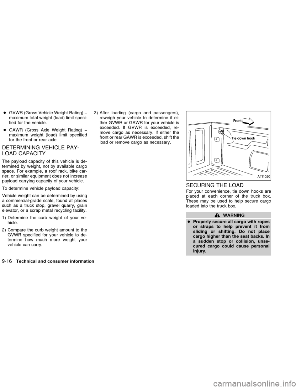
For your convenience, tie down hooks are
placed at each corner of the truck box.
These may be used to help secure cargo
loaded into the truck box.
WARNING
cProperly secure all cargo with ropes
or straps to help prevent it from
sliding or shifting. Do not place
cargo higher than the seat backs. In
a sudden stop or collision, unse-
cured cargo could cause personal
injury.
ATI1020
9-16Technical and consumer information
ZX