NISSAN FRONTIER 2010 Owner´s Manual
Manufacturer: NISSAN, Model Year: 2010, Model line: FRONTIER, Model: NISSAN FRONTIER 2010Pages: 373, PDF Size: 6.21 MB
Page 161 of 373
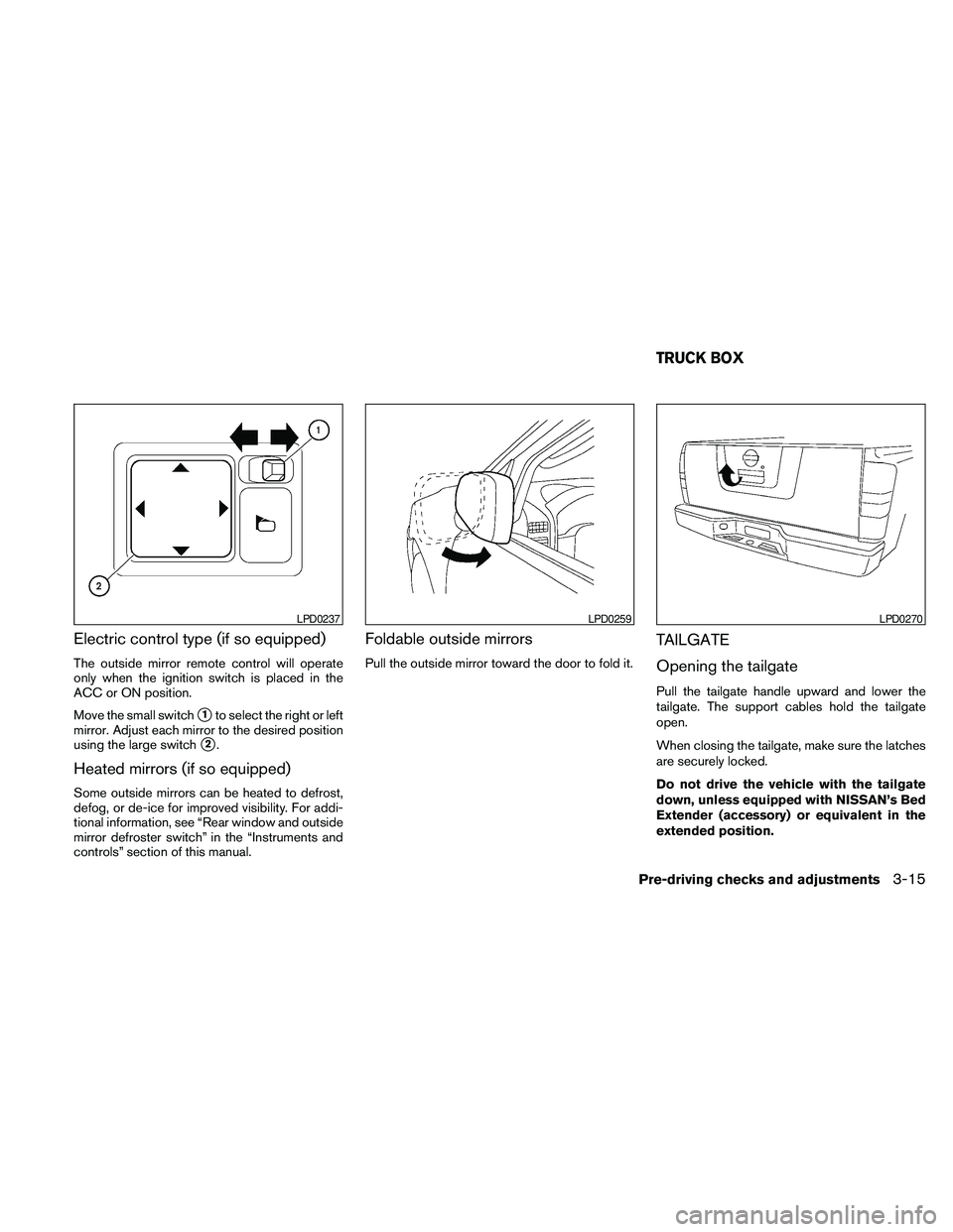
Electric control type (if so equipped)
The outside mirror remote control will operate
only when the ignition switch is placed in the
ACC or ON position.
Move the small switch
s1to select the right or left
mirror. Adjust each mirror to the desired position
using the large switch
s2.
Heated mirrors (if so equipped)
Some outside mirrors can be heated to defrost,
defog, or de-ice for improved visibility. For addi-
tional information, see “Rear window and outside
mirror defroster switch” in the “Instruments and
controls” section of this manual.
Foldable outside mirrors
Pull the outside mirror toward the door to fold it.
TAILGATE
Opening the tailgate
Pull the tailgate handle upward and lower the
tailgate. The support cables hold the tailgate
open.
When closing the tailgate, make sure the latches
are securely locked.
Do not drive the vehicle with the tailgate
down, unless equipped with NISSAN’s Bed
Extender (accessory) or equivalent in the
extended position.
LPD0237LPD0259LPD0270
TRUCK BOX
Pre-driving checks and adjustments3-15
Page 162 of 373
For proper truck box loading see “Vehicle loading
information” in the “Technical and consumer in-
formation” section of this manual.
WARNING
cIt is extremely dangerous to ride in a
cargo area inside a vehicle. In a colli-
sion, people riding in these areas are
more likely to be seriously injured or
killed.
cDo not allow people to ride in any area
of your vehicle that is not equipped with
seats and seat belts.
cBe sure everyone in your vehicle is in a
seat and using a seat belt properly.
Removing the tailgate
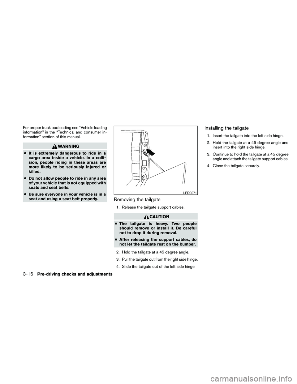
1. Release the tailgate support cables.
CAUTION
cThe tailgate is heavy. Two people
should remove or install it. Be careful
not to drop it during removal.
cAfter releasing the support cables, do
not let the tailgate rest on the bumper.
2. Hold the tailgate at a 45 degree angle.
3. Pull the tailgate out from the right side hinge.
4. Slide the tailgate out of the left side hinge.
Installing the tailgate
1. Insert the tailgate into the left side hinge.
2. Hold the tailgate at a 45 degree angle and
insert into the right side hinge.
3. Continue to hold the tailgate at a 45 degree
angle and attach the tailgate support cables.
4. Close the tailgate securely.
LPD0271
3-16Pre-driving checks and adjustments
Page 163 of 373
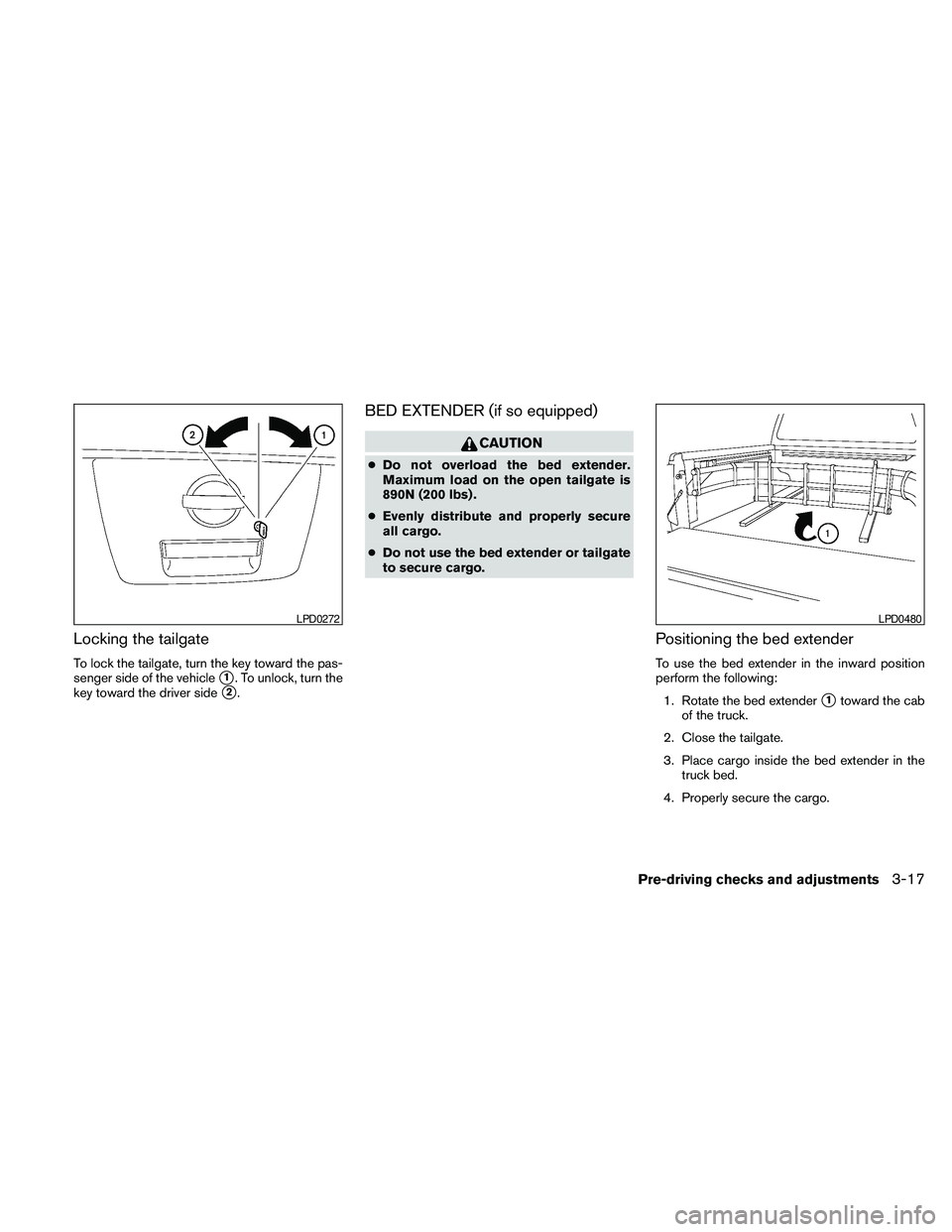
Locking the tailgate
To lock the tailgate, turn the key toward the pas-
senger side of the vehicle
s1. To unlock, turn the
key toward the driver side
s2.
BED EXTENDER (if so equipped)
CAUTION
cDo not overload the bed extender.
Maximum load on the open tailgate is
890N (200 lbs) .
cEvenly distribute and properly secure
all cargo.
cDo not use the bed extender or tailgate
to secure cargo.
Positioning the bed extender
To use the bed extender in the inward position
perform the following:
1. Rotate the bed extender
s1toward the cab
of the truck.
2. Close the tailgate.
3. Place cargo inside the bed extender in the
truck bed.
4. Properly secure the cargo.
LPD0272LPD0480
Pre-driving checks and adjustments3-17
Page 164 of 373
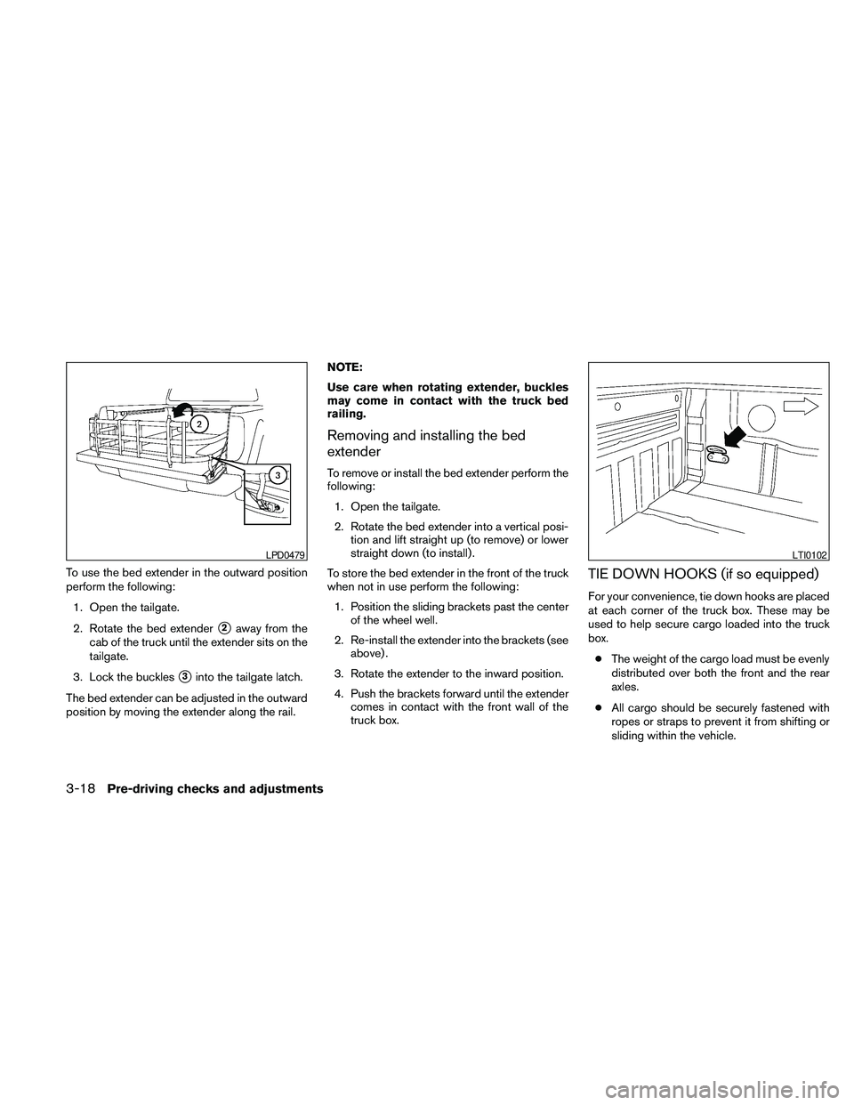
To use the bed extender in the outward position
perform the following:
1. Open the tailgate.
2. Rotate the bed extender
s2away from the
cab of the truck until the extender sits on the
tailgate.
3. Lock the buckles
s3into the tailgate latch.
The bed extender can be adjusted in the outward
position by moving the extender along the rail.NOTE:
Use care when rotating extender, buckles
may come in contact with the truck bed
railing.
Removing and installing the bed
extender
To remove or install the bed extender perform the
following:
1. Open the tailgate.
2. Rotate the bed extender into a vertical posi-
tion and lift straight up (to remove) or lower
straight down (to install) .
To store the bed extender in the front of the truck
when not in use perform the following:
1. Position the sliding brackets past the center
of the wheel well.
2. Re-install the extender into the brackets (see
above) .
3. Rotate the extender to the inward position.
4. Push the brackets forward until the extender
comes in contact with the front wall of the
truck box.
TIE DOWN HOOKS (if so equipped)
For your convenience, tie down hooks are placed
at each corner of the truck box. These may be
used to help secure cargo loaded into the truck
box.
cThe weight of the cargo load must be evenly
distributed over both the front and the rear
axles.
cAll cargo should be securely fastened with
ropes or straps to prevent it from shifting or
sliding within the vehicle.
LPD0479LTI0102
3-18Pre-driving checks and adjustments
Page 165 of 373
WARNING
cProperly secure all cargo with ropes or
straps to help prevent it from sliding or
shifting. In a sudden stop or collision,
unsecured cargo could cause personal
injury.
Pre-driving checks and adjustments3-19
Page 166 of 373

MEMO
3-20Pre-driving checks and adjustments
Page 167 of 373
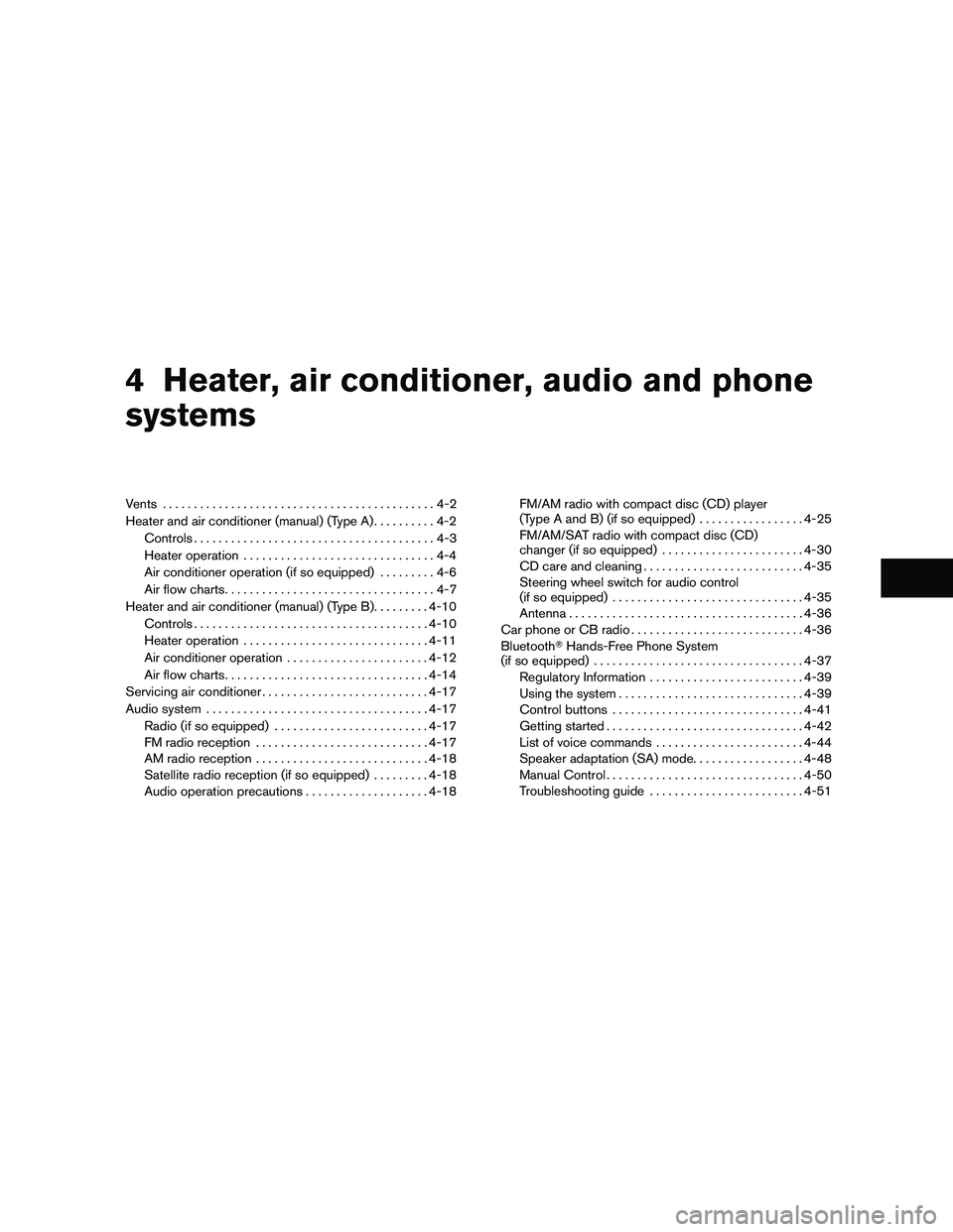
4 Heater, air conditioner, audio and phone
systems
Vents............................................4-2
Heater and air conditioner (manual) (Type A)..........4-2
Controls.......................................4-3
Heater operation...............................4-4
Air conditioner operation (if so equipped).........4-6
Air flow charts..................................4-7
Heater and air conditioner (manual) (Type B).........4-10
Controls......................................4-10
Heater operation..............................4-11
Air conditioner operation.......................4-12
Air flow charts.................................4-14
Servicing air conditioner...........................4-17
Audio system....................................4-17
Radio (if so equipped).........................4-17
FM radio reception............................4-17
AM radio reception............................4-18
Satellite radio reception (if so equipped).........4-18
Audio operation precautions....................4-18FM/AM radio with compact disc (CD) player
(Type A and B) (if so equipped).................4-25
FM/AM/SAT radio with compact disc (CD)
changer (if so equipped).......................4-30
CD care and cleaning..........................4-35
Steering wheel switch for audio control
(if so equipped)...............................4-35
Antenna......................................4-36
Car phone or CB radio............................4-36
BluetoothTHands-Free Phone System
(if so equipped)..................................4-37
Regulatory Information.........................4-39
Using the system..............................4-39
Control buttons...............................4-41
Getting started................................4-42
List of voice commands........................4-44
Speaker adaptation (SA) mode..................4-48
Manual Control................................4-50
Troubleshooting guide.........................4-51
Page 168 of 373
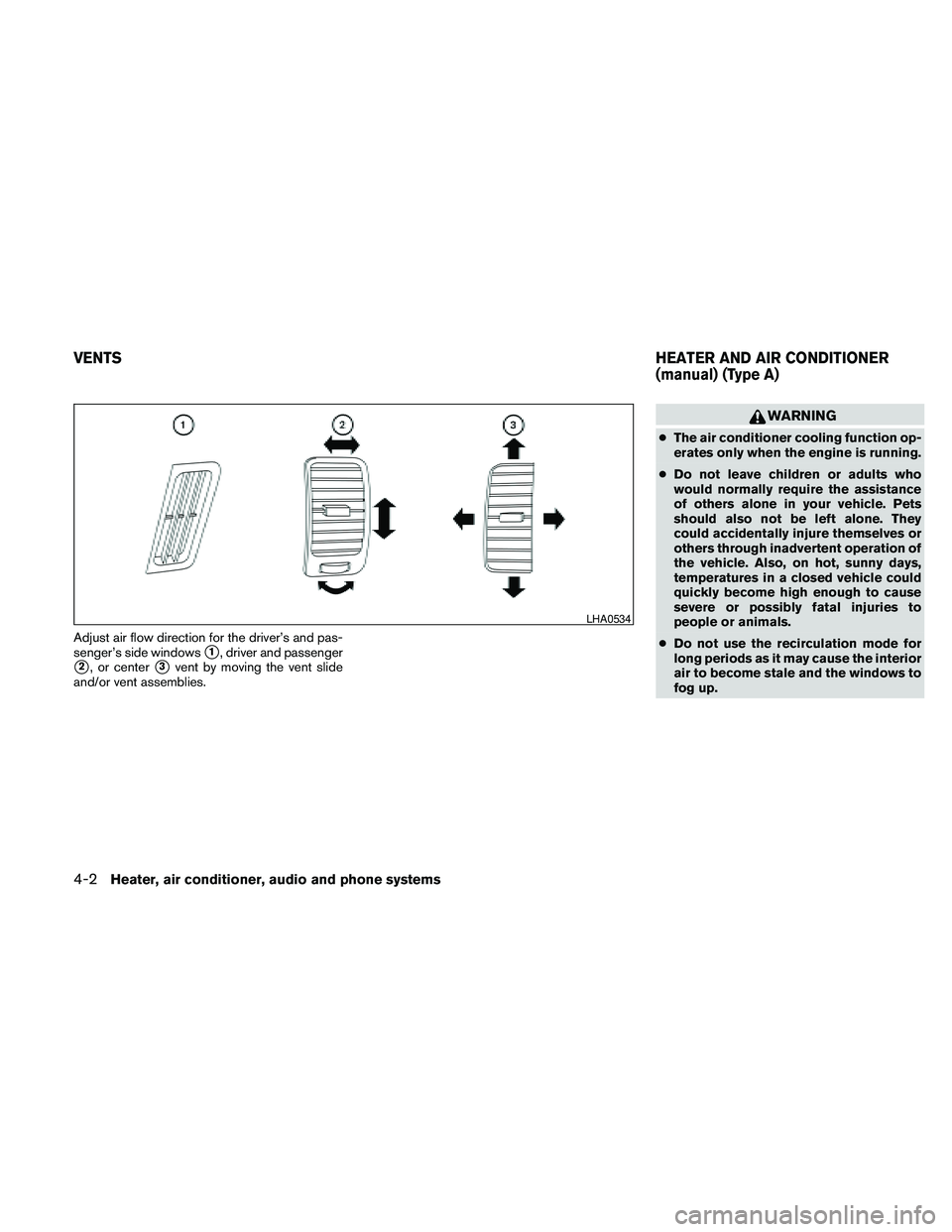
Adjust air flow direction for the driver’s and pas-
senger’s side windows
s1, driver and passenger
s2, or centers3vent by moving the vent slide
and/or vent assemblies.
WARNING
cThe air conditioner cooling function op-
erates only when the engine is running.
cDo not leave children or adults who
would normally require the assistance
of others alone in your vehicle. Pets
should also not be left alone. They
could accidentally injure themselves or
others through inadvertent operation of
the vehicle. Also, on hot, sunny days,
temperatures in a closed vehicle could
quickly become high enough to cause
severe or possibly fatal injuries to
people or animals.
cDo not use the recirculation mode for
long periods as it may cause the interior
air to become stale and the windows to
fog up.
LHA0534
VENTSHEATER AND AIR CONDITIONER
(manual) (Type A)
4-2Heater, air conditioner, audio and phone systems
Page 169 of 373
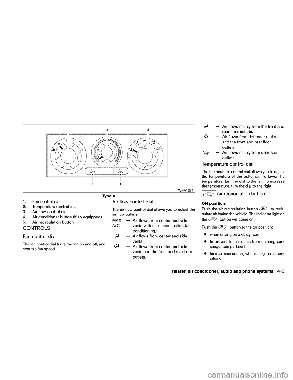
1. Fan control dial
2. Temperature control dial
3. Air flow control dial
4. Air conditioner button (if so equipped)
5. Air recirculation button
CONTROLS
Fan control dial
The fan control dial turns the fan on and off, and
controls fan speed.
Air flow control dial
The air flow control dial allows you to select the
air flow outlets.
MAX
A/C— Air flows from center and side
vents with maximum cooling (air
conditioning) .
— Air flows from center and side
vents.
— Air flows from center and side
vents and the front and rear floor
outlets.
— Air flows mainly from the front and
rear floor outlets.
— Air flows from defroster outlets
and the front and rear floor
outlets.
— Air flows mainly from defroster
outlets.
Temperature control dial
The temperature control dial allows you to adjust
the temperature of the outlet air. To lower the
temperature, turn the dial to the left. To increase
the temperature, turn the dial to the right.
Air recirculation button
ON position:
Push the air recirculation button
to recir-
culate air inside the vehicle. The indicator light on
the
button will come on.
Push the
button to the on position:
cwhen driving on a dusty road.
cto prevent traffic fumes from entering pas-
senger compartment.
cfor maximum cooling when using the air con-
ditioner.
Type A
WHA1384
Heater, air conditioner, audio and phone systems4-3
Page 170 of 373
OFF position:
Push the air recirculation button
again to
turn air recirculation off. The indicator light on
the
button will turn off. Outside air is drawn
into the passenger compartment and distributed
through the selected outlet.
Use the off position for normal heater or air con-
ditioner operation.
Air conditioner button (if so
equipped)
The button is provided only on vehicles equipped
with an air conditioner.
Start the engine, turn the fan control dial to the
desired (1 - 4) position and push the
button to turn on the air conditioner. The indicator
light comes on when the air conditioner is oper-
ating. To turn off the air conditioner, push
the
button again.
The air conditioner cooling function oper-
ates only when the engine is running.
HEATER OPERATION
Heating
This mode is used to direct heated air to the foot
outlets. Some air also flows from the defrost
outlets.
1. Push the
button to the OFF position
for normal heating. The indicator light on
the
button will go off.
2. Turn the air flow control dial to the
position.
3. Turn the fan control dial to the desired posi-
tion.
4. Turn the temperature control dial to the de-
sired position between the middle and the
hot position.
Ventilation
This mode directs outside air to the side and
center vent.
1. Push the
button to the OFF position.
The indicator light on the
button will
go off.
2. Turn the air flow control dial to the
position.3. Turn the fan control dial to the desired posi-
tion.
4. Turn the temperature control dial to the de-
sired position.
Defrosting or defogging
This mode directs the air to the defrost outlets to
defrost/defog the windows.
1. Turn the air flow control dial to the
position.
2. Turn the fan control dial to the desired posi-
tion.
3. Turn the temperature control dial to the de-
sired position between the middle and the
hot position.
cTo quickly remove ice or fog from the win-
dows, turn the fan control dial to 4 and the
temperature control lever to the full HOT
position.
4-4Heater, air conditioner, audio and phone systems