phone NISSAN FRONTIER 2010 Owner´s Manual
[x] Cancel search | Manufacturer: NISSAN, Model Year: 2010, Model line: FRONTIER, Model: NISSAN FRONTIER 2010Pages: 373, PDF Size: 6.21 MB
Page 5 of 373
NISSAN CARES...
Both NISSAN and your NISSAN dealer are dedicated to serving all your automotive needs. Your satisfaction with your vehicle and your NISSAN dealer are
our primary concerns. Your NISSAN dealer is always available to assist you with all your automobile sales and service needs.
However, if there is something that your NISSAN
dealer cannot assist you with or you would like to
provide NISSAN directly with comments or
questions, please contact the NISSAN Con-
sumer Affairs Department using our toll-free
number:
For U.S. customers
1-800-NISSAN-1
(1-800-647-7261)
For Canadian customers
1-800-387-0122The Consumer Affairs Department will ask for the
following information:
– Your name, address, and telephone number
– Vehicle identification number (attached to the
top of the instrument panel on the driver’s
side)
– Date of purchase
– Current odometer reading
– Your NISSAN dealer’s name
– Your comments or questions
ORYou can write to NISSAN with the information at:
For U.S. customers
Nissan North America, Inc.
Consumer Affairs Department
P.O. Box 685003
Franklin, TN 37068-5003
For Canadian customers
Nissan Canada Inc.
5290 Orbitor Drive
Mississauga, Ontario L4W 4Z5
We appreciate your interest in NISSAN and thank you for buying a quality NISSAN vehicle.
NISSAN CUSTOMER CARE PROGRAM
Page 6 of 373
Table of
ContentsIllustrated table of contents
Safety—Seats, seat belts and supplemental restraint system
Instruments and controls
Pre-driving checks and adjustments
Heater, air conditioner, audio and phone systems
Starting and driving
In case of emergency
Appearance and care
Maintenance and do-it-yourself
Technical and consumer information
Index
0
1
2
3
4
5
6
7
8
9
10
Page 12 of 373

1. Vents (P. 4-2)
2. Headlight/fog light (if so equipped)/turn
signal switch (P. 2-26)
3. Steering wheel switch for audio control
(if so equipped)/BluetoothTHands-
Free Phone System (if so equipped)
(P. 4-35, P. 4-37)
4. Driver supplemental air bag/horn
(P. 1-57, P. 2-31)
5. Meters, gauges and warning/indicator
lights (P. 2-3, 2-13)
6. Cruise control main/set switches
(if so equipped) (P. 5-20)
7. Windshield wiper/washer switch
(P. 2-25)
8. Storage (P. 2-36)
9. Audio system controls (if so equipped)
(P. 4-17)
10. Front passenger supplemental air bag
(P. 1-57)
11. Upper and lower glove box (P. 2-40)
12. Passenger air bag status light (P. 1-66)
13. Auxiliary audio input jack
(if so equipped) (P. 4-34)
14. Power outlet (P. 2-35)
LIC1422
INSTRUMENT PANEL
0-6Illustrated table of contents
Page 94 of 373

1. Vents (P. 4-2)
2. Headlight/fog light (if so equipped)/turn
signal switch (P. 2-26)
3. Steering wheel switch for audio control
(if so equipped)/BluetoothTHands-
Free Phone System (if so equipped)
(P. 4-35, P. 4-37)
4. Driver supplemental air bag/horn
(P. 1-57, P. 2-31)
5. Meters, gauges and warning/indicator
lights (P. 2-3, 2-13)
6. Cruise control main/set switches
(if so equipped) (P. 5-20)
7. Windshield wiper/washer switch
(P. 2-25)
8. Storage (P. 2-36)
9. Audio system controls (if so equipped)
(P. 4-17)
10. Front passenger supplemental air bag
(P. 1-57)
11. Upper and lower glove box (P. 2-40)
12. Passenger air bag status light (P. 1-66)
13. Auxiliary audio input jack
(if so equipped) (P. 4-34)
14. Power outlet (P. 2-35)
LIC1422
INSTRUMENT PANEL
2-2Instruments and controls
Page 127 of 373
WARNING
Pay special attention to your surround-
ings when using the clutch interlock
switch. The vehicle will move forward or
backward according to the gear selected.
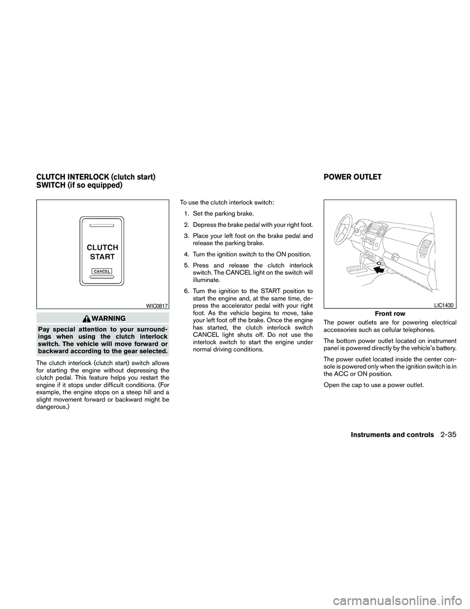
The clutch interlock (clutch start) switch allows
for starting the engine without depressing the
clutch pedal. This feature helps you restart the
engine if it stops under difficult conditions. (For
example, the engine stops on a steep hill and a
slight movement forward or backward might be
dangerous.)To use the clutch interlock switch:
1. Set the parking brake.
2. Depress the brake pedal with your right foot.
3. Place your left foot on the brake pedal and
release the parking brake.
4. Turn the ignition switch to the ON position.
5. Press and release the clutch interlock
switch. The CANCEL light on the switch will
illuminate.
6. Turn the ignition to the START position to
start the engine and, at the same time, de-
press the accelerator pedal with your right
foot. As the vehicle begins to move, take
your left foot off the brake. Once the engine
has started, the clutch interlock switch
CANCEL light shuts off. Do not use the
interlock switch to start the engine under
normal driving conditions.The power outlets are for powering electrical
accessories such as cellular telephones.
The bottom power outlet located on instrument
panel is powered directly by the vehicle’s battery.
The power outlet located inside the center con-
sole is powered only when the ignition switch is in
the ACC or ON position.
Open the cap to use a power outlet.
WIC0817
Front row
LIC1430
CLUTCH INTERLOCK (clutch start)
SWITCH (if so equipped)POWER OUTLET
Instruments and controls2-35
Page 146 of 373
cposition the hand-held transmitter1-3
inches (26 - 76 mm) away from the
HomeLinkTsurface. Hold the transmitter in
that position for up to 15 seconds. If
HomeLinkTis not programmed within that
time, try holding the transmitter in another
position – keeping the indicator light in view
at all times.
If you continue to have programming difficulties,
please contact the NISSAN Consumer Affairs
Department. The phone numbers are located in
the Foreword of this manual.
CLEARING THE PROGRAMMED
INFORMATION
Individual buttons cannot be cleared. However,
to clear all programming, press and hold the two
outside buttons and release when the indicator
light begins to flash (approximately 20 seconds) .
REPROGRAMMING A SINGLE
HOMELINKTBUTTON
To reprogram a HomeLinkTUniversal Transceiver
button, complete the following.
1. Press and hold the desired HomeLinkTbut-
ton.Do notrelease the button until step 4
has been completed.2. When the indicator light begins to flash
slowly (after 20 seconds) , position the
hand-held transmitter1-3inches (26 - 76
mm) away from the HomeLinkTsurface.
3. Press and hold the hand-held transmitter
button.
4. The HomeLinkTindicator light will flash, first
slowly and then rapidly. When the indicator
light begins to flash rapidly, release both
buttons.
The HomeLinkTUniversal Transceiver button has
now been reprogrammed. The new device can
be activated by pushing the HomeLinkTbutton
that was just programmed. This procedure will
not affect any other programmed HomeLinkT
buttons.
IF YOUR VEHICLE IS STOLEN
If your vehicle is stolen, you should change the
codes of any non-rolling code device that has
been programmed into HomeLinkT. Consult the
Owner’s Manual of each device or call the manu-
facturer or dealer of those devices for additional
information.
When your vehicle is recovered, you will
need to reprogram the HomeLinkTUniver-
sal Transceiver with your new transmitter
information.FCC Notice:
This device complies with FCC rules part 15
and RSS-210 of Industry Canada. Opera-
tion is subject to the following two condi-
tions:
(1) This device may not cause harmful in-
terference and (2) This device must accept
any interference that may be received, in-
cluding interference that may cause undes-
ired operation.
This transmitter has been tested and com-
plies with FCC and DOC/MDC rules.
Changes or modifications not expressly ap-
proved by the party responsible for compli-
ance could void the user’s authority to op-
erate the equipment.
DOC: ISTC 1763K1313
FCC I.D. CV2V67690
2-54Instruments and controls
Page 167 of 373
4 Heater, air conditioner, audio and phone
systems
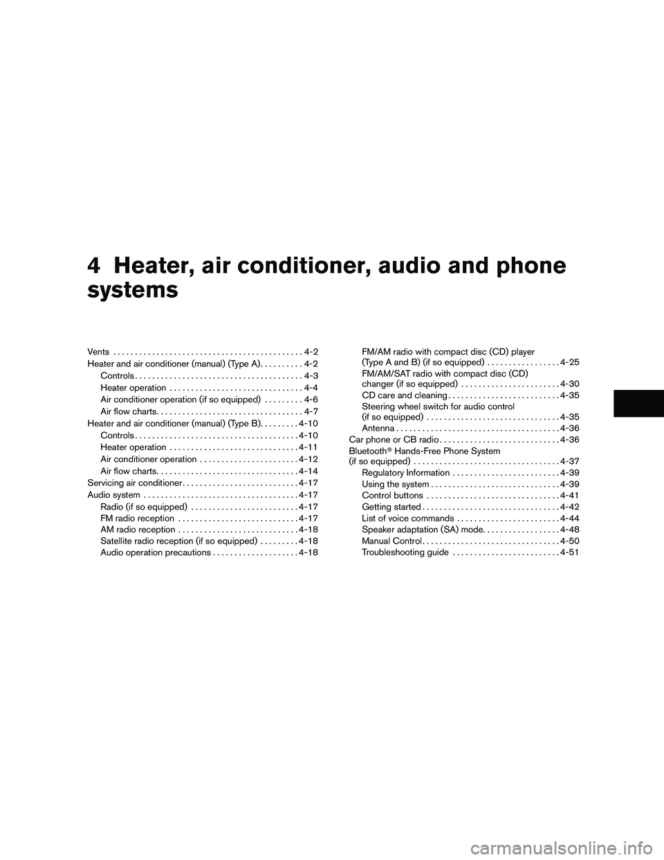
Vents............................................4-2
Heater and air conditioner (manual) (Type A)..........4-2
Controls.......................................4-3
Heater operation...............................4-4
Air conditioner operation (if so equipped).........4-6
Air flow charts..................................4-7
Heater and air conditioner (manual) (Type B).........4-10
Controls......................................4-10
Heater operation..............................4-11
Air conditioner operation.......................4-12
Air flow charts.................................4-14
Servicing air conditioner...........................4-17
Audio system....................................4-17
Radio (if so equipped).........................4-17
FM radio reception............................4-17
AM radio reception............................4-18
Satellite radio reception (if so equipped).........4-18
Audio operation precautions....................4-18FM/AM radio with compact disc (CD) player
(Type A and B) (if so equipped).................4-25
FM/AM/SAT radio with compact disc (CD)
changer (if so equipped).......................4-30
CD care and cleaning..........................4-35
Steering wheel switch for audio control
(if so equipped)...............................4-35
Antenna......................................4-36
Car phone or CB radio............................4-36
BluetoothTHands-Free Phone System
(if so equipped)..................................4-37
Regulatory Information.........................4-39
Using the system..............................4-39
Control buttons...............................4-41
Getting started................................4-42
List of voice commands........................4-44
Speaker adaptation (SA) mode..................4-48
Manual Control................................4-50
Troubleshooting guide.........................4-51
Page 168 of 373
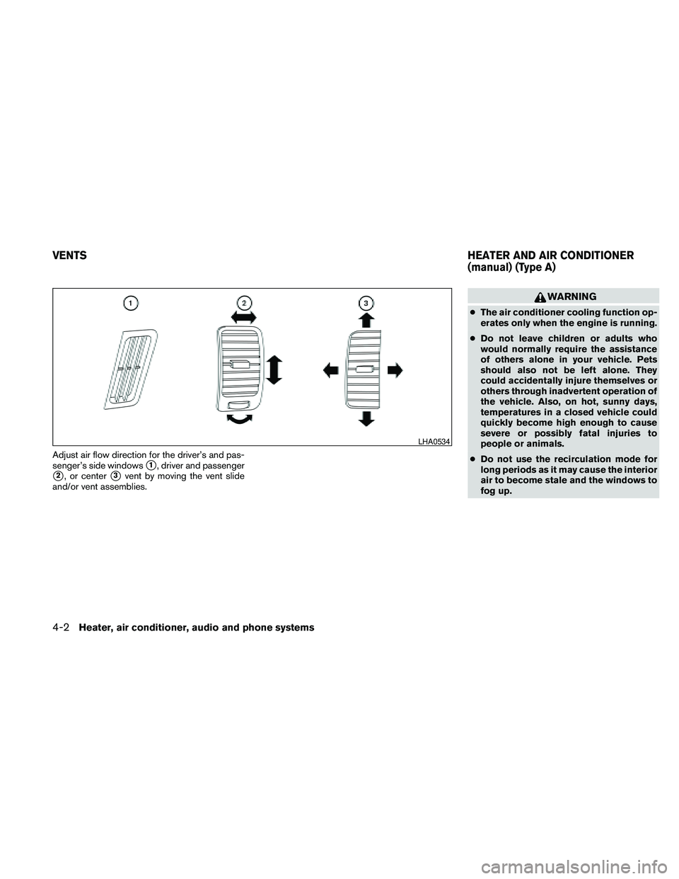
Adjust air flow direction for the driver’s and pas-
senger’s side windows
s1, driver and passenger
s2, or centers3vent by moving the vent slide
and/or vent assemblies.
WARNING
cThe air conditioner cooling function op-
erates only when the engine is running.
cDo not leave children or adults who
would normally require the assistance
of others alone in your vehicle. Pets
should also not be left alone. They
could accidentally injure themselves or
others through inadvertent operation of
the vehicle. Also, on hot, sunny days,
temperatures in a closed vehicle could
quickly become high enough to cause
severe or possibly fatal injuries to
people or animals.
cDo not use the recirculation mode for
long periods as it may cause the interior
air to become stale and the windows to
fog up.
LHA0534
VENTSHEATER AND AIR CONDITIONER
(manual) (Type A)
4-2Heater, air conditioner, audio and phone systems
Page 169 of 373
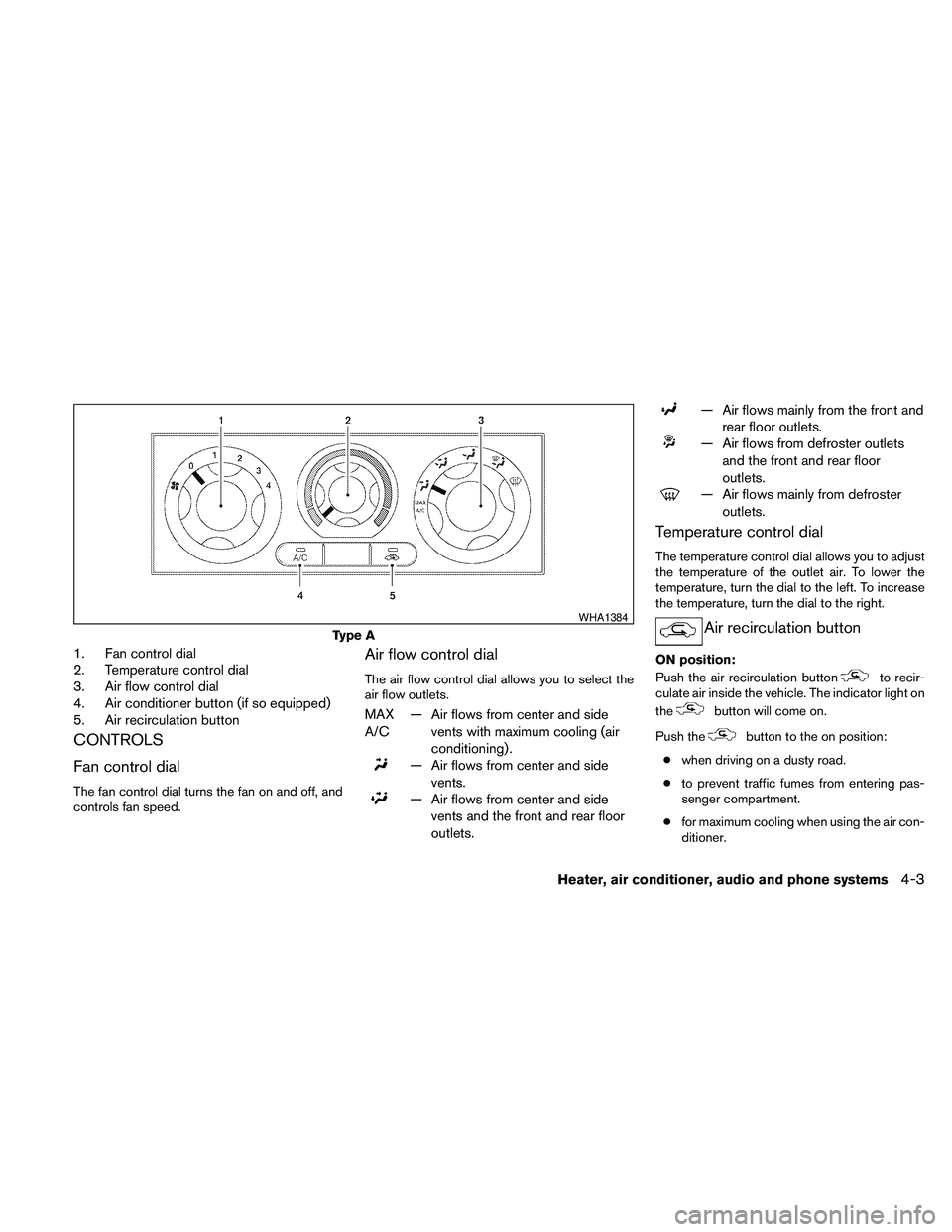
1. Fan control dial
2. Temperature control dial
3. Air flow control dial
4. Air conditioner button (if so equipped)
5. Air recirculation button
CONTROLS
Fan control dial
The fan control dial turns the fan on and off, and
controls fan speed.
Air flow control dial
The air flow control dial allows you to select the
air flow outlets.
MAX
A/C— Air flows from center and side
vents with maximum cooling (air
conditioning) .
— Air flows from center and side
vents.
— Air flows from center and side
vents and the front and rear floor
outlets.
— Air flows mainly from the front and
rear floor outlets.
— Air flows from defroster outlets
and the front and rear floor
outlets.
— Air flows mainly from defroster
outlets.
Temperature control dial
The temperature control dial allows you to adjust
the temperature of the outlet air. To lower the
temperature, turn the dial to the left. To increase
the temperature, turn the dial to the right.
Air recirculation button
ON position:
Push the air recirculation button
to recir-
culate air inside the vehicle. The indicator light on
the
button will come on.
Push the
button to the on position:
cwhen driving on a dusty road.
cto prevent traffic fumes from entering pas-
senger compartment.
cfor maximum cooling when using the air con-
ditioner.
Type A
WHA1384
Heater, air conditioner, audio and phone systems4-3
Page 170 of 373
OFF position:
Push the air recirculation button
again to
turn air recirculation off. The indicator light on
the
button will turn off. Outside air is drawn
into the passenger compartment and distributed
through the selected outlet.
Use the off position for normal heater or air con-
ditioner operation.
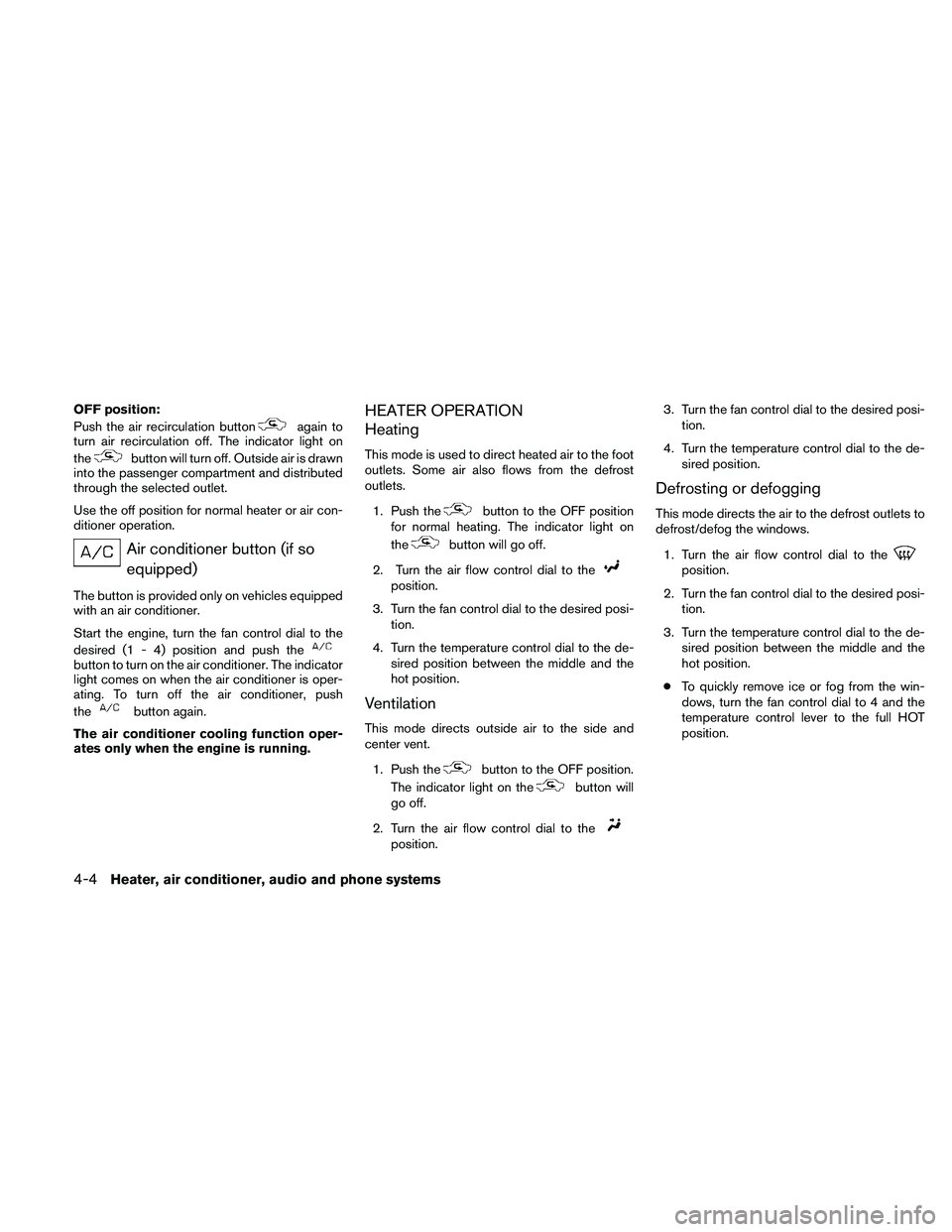
Air conditioner button (if so
equipped)
The button is provided only on vehicles equipped
with an air conditioner.
Start the engine, turn the fan control dial to the
desired (1 - 4) position and push the
button to turn on the air conditioner. The indicator
light comes on when the air conditioner is oper-
ating. To turn off the air conditioner, push
the
button again.
The air conditioner cooling function oper-
ates only when the engine is running.
HEATER OPERATION
Heating
This mode is used to direct heated air to the foot
outlets. Some air also flows from the defrost
outlets.
1. Push the
button to the OFF position
for normal heating. The indicator light on
the
button will go off.
2. Turn the air flow control dial to the
position.
3. Turn the fan control dial to the desired posi-
tion.
4. Turn the temperature control dial to the de-
sired position between the middle and the
hot position.
Ventilation
This mode directs outside air to the side and
center vent.
1. Push the
button to the OFF position.
The indicator light on the
button will
go off.
2. Turn the air flow control dial to the
position.3. Turn the fan control dial to the desired posi-
tion.
4. Turn the temperature control dial to the de-
sired position.
Defrosting or defogging
This mode directs the air to the defrost outlets to
defrost/defog the windows.
1. Turn the air flow control dial to the
position.
2. Turn the fan control dial to the desired posi-
tion.
3. Turn the temperature control dial to the de-
sired position between the middle and the
hot position.
cTo quickly remove ice or fog from the win-
dows, turn the fan control dial to 4 and the
temperature control lever to the full HOT
position.
4-4Heater, air conditioner, audio and phone systems