NISSAN FRONTIER 2020 Owner´s Manual
Manufacturer: NISSAN, Model Year: 2020, Model line: FRONTIER, Model: NISSAN FRONTIER 2020Pages: 492, PDF Size: 3.05 MB
Page 181 of 492
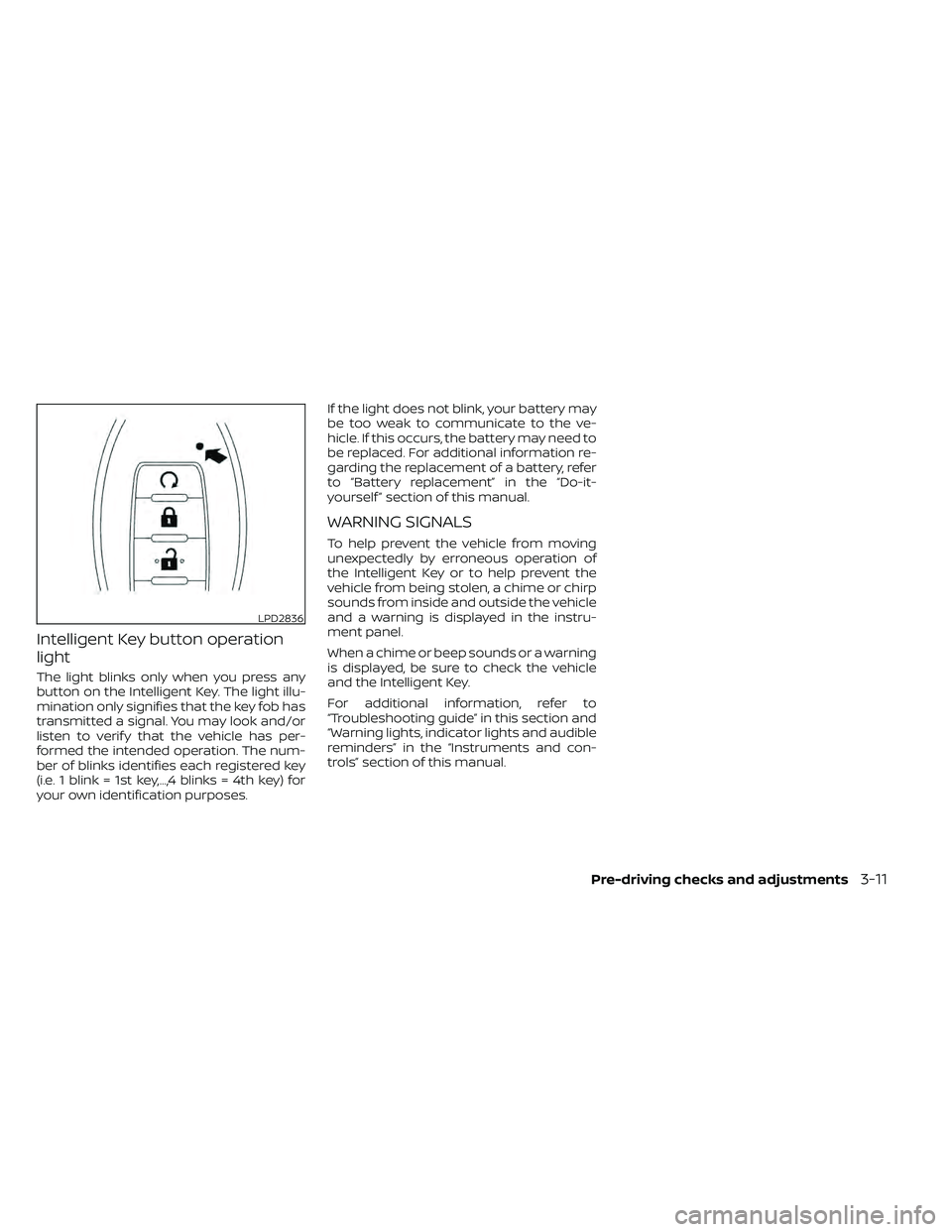
Intelligent Key button operation
light
The light blinks only when you press any
button on the Intelligent Key. The light illu-
mination only signifies that the key fob has
transmitted a signal. You may look and/or
listen to verif y that the vehicle has per-
formed the intended operation. The num-
ber of blinks identifies each registered key
(i.e. 1 blink = 1st key,...,4 blinks = 4th key) for
your own identification purposes.If the light does not blink, your battery may
be too weak to communicate to the ve-
hicle. If this occurs, the battery may need to
be replaced. For additional information re-
garding the replacement of a battery, refer
to “Battery replacement” in the “Do-it-
yourself ” section of this manual.
WARNING SIGNALS
To help prevent the vehicle from moving
unexpectedly by erroneous operation of
the Intelligent Key or to help prevent the
vehicle from being stolen, a chime or chirp
sounds from inside and outside the vehicle
and a warning is displayed in the instru-
ment panel.
When a chime or beep sounds or a warning
is displayed, be sure to check the vehicle
and the Intelligent Key.
For additional information, refer to
“Troubleshooting guide” in this section and
“Warning lights, indicator lights and audible
reminders” in the “Instruments and con-
trols” section of this manual.
LPD2836
Pre-driving checks and adjustments3-11
Page 182 of 492
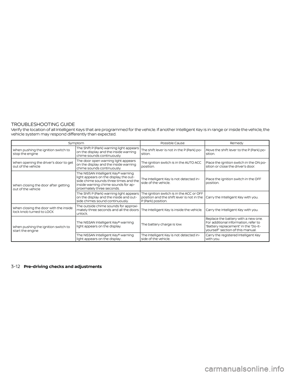
TROUBLESHOOTING GUIDE
Verif y the location of all Intelligent Keys that are programmed for the vehicle. If another Intelligent Key is in range or inside the vehicle, the
vehicle system may respond differently than expected.
SymptomPossible CauseRemedy
When pushing the ignition switch to
stop the engine The Shif t P (Park) warning light appears
on the display and the inside warning
chime sounds continuously. The shif t lever is not in the P (Park) po-
sition.
Move the shif t lever to the P (Park) po-
sition.
When opening the driver's door to get
out of the vehicle The door open warning light appears
on the display and the inside warning
chime sounds continuously. The ignition switch is in the AUTO ACC
position.
Place the ignition switch in the ON po-
sition or close the driver’s door.
When closing the door af ter getting
out of the vehicle The NISSAN Intelligent Key® warning
light appears on the display, the out-
side chime sounds three times and the
inside warning chime sounds for ap-
proximately three seconds.
The Intelligent Key is not detected in-
side of the vehicle.
Place the ignition switch in the OFF
position.
The Shif t P (Park) warning light appears
on the display and the inside and out-
side chimes sound continuously. The ignition switch is in the ACC or OFF
position and the shif t lever is not in the
P (Park) position.
Carry the Intelligent Key with you.
When closing the door with the inside
lock knob turned to LOCK The outside chime sounds for approxi-
mately three seconds and all the doors
unlock.
The Intelligent Key is inside the vehicle. Carry the Intelligent Key with you.
When pushing the ignition switch to
start the engine The NISSAN Intelligent Key® warning
light appears on the display.
The battery charge is low.Replace the battery with a new one.
For additional information, refer to
“Battery replacement” in the “Do-it-
yourself ” section of this manual.
The NISSAN Intelligent Key® warning
light appears on the display . The Intelligent Key is not detected in-
side of the vehicle.Carry the registered Intelligent Key
with you.
3-12Pre-driving checks and adjustments
Page 183 of 492
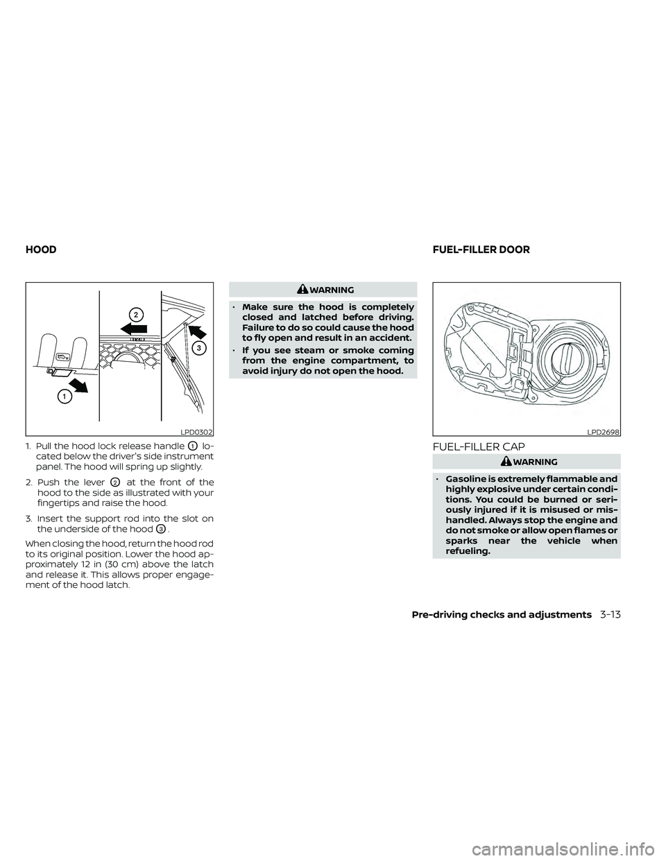
1. Pull the hood lock release handleO1lo-
cated below the driver's side instrument
panel. The hood will spring up slightly.
2. Push the lever
O2at the front of the
hood to the side as illustrated with your
fingertips and raise the hood.
3. Insert the support rod into the slot on the underside of the hood
O3.
When closing the hood, return the hood rod
to its original position. Lower the hood ap-
proximately 12 in (30 cm) above the latch
and release it. This allows proper engage-
ment of the hood latch.
WARNING
• Make sure the hood is completely
closed and latched before driving.
Failure to do so could cause the hood
to fly open and result in an accident.
• If you see steam or smoke coming
from the engine compartment, to
avoid injury do not open the hood.
FUEL-FILLER CAP
WARNING
• Gasoline is extremely flammable and
highly explosive under certain condi-
tions. You could be burned or seri-
ously injured if it is misused or mis-
handled. Always stop the engine and
do not smoke or allow open flames or
sparks near the vehicle when
refueling.
LPD0302LPD2698
HOOD FUEL-FILLER DOOR
Pre-driving checks and adjustments3-13
Page 184 of 492
•Do not attempt to top off the fuel
tank af ter the fuel pump nozzle
shuts off automatically. Continued
refueling may cause fuel overflow,
resulting in fuel spray and possibly a
fire.
• Use only an original equipment type
fuel-filler cap as a replacement. It has
a built-in safety valve needed for
proper operation of the fuel system
and emission control system. An in-
correct cap can result in a serious
malfunction and possible injury. It
could also cause the
Malfunc-
tion Indicator Light (MIL) to come on.
• Never pour fuel into the throttle body
to attempt to start your vehicle.
• Do not fill a portable fuel container in
the vehicle or trailer. Static electricity
can cause an explosion of flammable
liquid, vapor or gas in any vehicle or
trailer. To reduce the risk of serious
injury or death when filling portable
fuel containers:
– Always place the container on the
ground when filling.
– Do not use electronic devices
when filling. –
Keep the pump nozzle in contact
with the container while you are
filling it.
– Use only approved portable fuel
containers for flammable liquid.
CAUTION
• Do not use a fuel containing more
than 15% ethanol in your vehicle. For
additional information, refer to “Fuel
recommendation” in the “Technical
and consumer information” section
of this manual.
• The LOOSE FUEL CAP warning will ap-
pear if the fuel-filler cap is not prop-
erly tightened. It may take a few driv-
ing trips for the message to be
displayed. Failure to tighten the fuel-
filler cap properly af ter the LOOSE
FUEL CAP warning appears may
cause the
Malfunction Indicator
Light (MIL) to illuminate. •
Failure to tighten the fuel-filler cap
properly may cause the
Mal-
function Indicator Light (MIL) to illu-
minate. If the
light illuminates
because the fuel-filler cap is loose or
missing, tighten or install the cap and
continue to drive the vehicle. The
light should turn off af ter a few
driving trips. If thelight does not
turn off af ter a few driving trips, have
your vehicle inspected. It is recom-
mended that you visit a NISSAN
dealer for this service.
• For additional information, refer to
“Malfunction Indicator Light (MIL)” in
the “Instruments and controls” sec-
tion in this manual.
• If fuel is spilled on the vehicle body,
flush it away with water to avoid
paint damage.
3-14Pre-driving checks and adjustments
Page 185 of 492
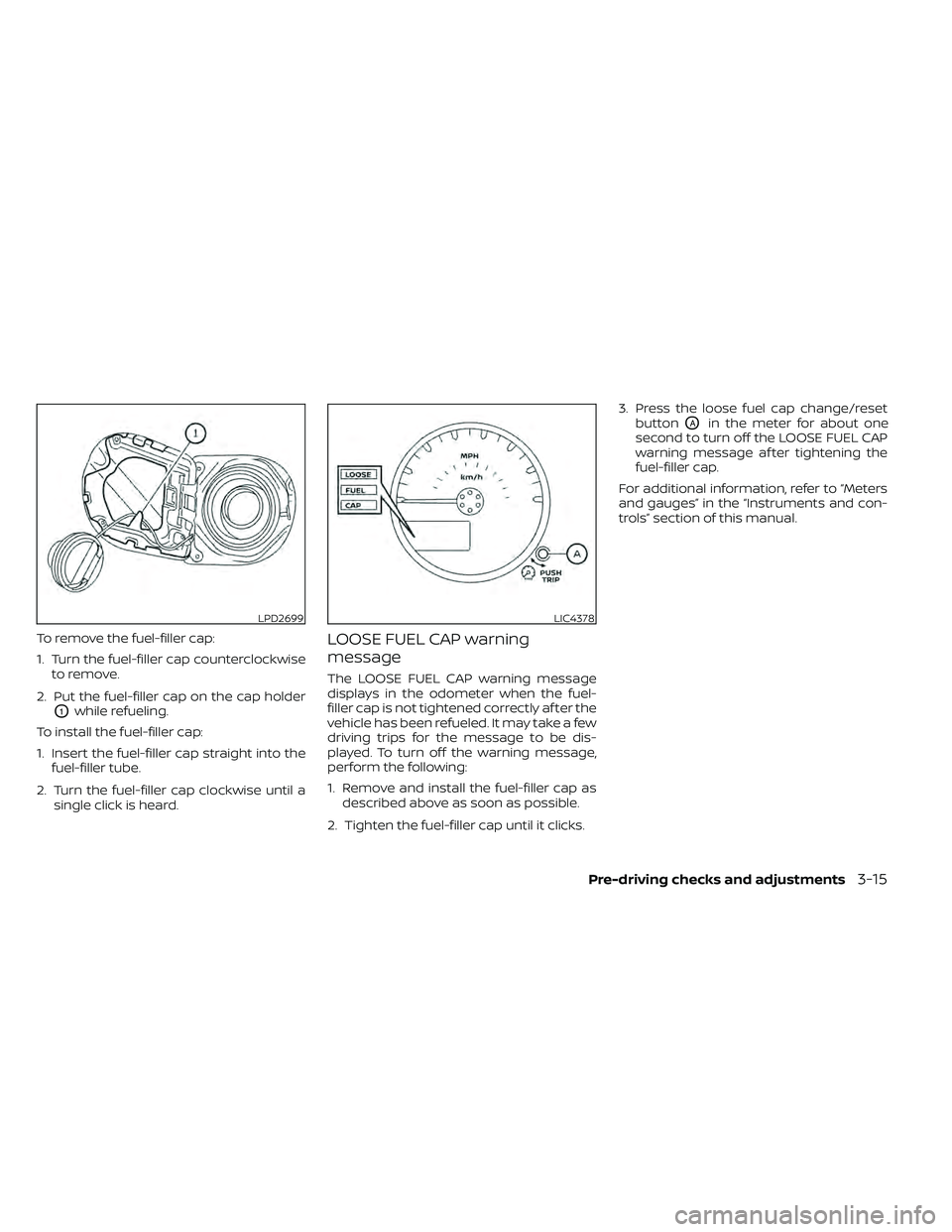
To remove the fuel-filler cap:
1. Turn the fuel-filler cap counterclockwiseto remove.
2. Put the fuel-filler cap on the cap holder
O1while refueling.
To install the fuel-filler cap:
1. Insert the fuel-filler cap straight into the fuel-filler tube.
2. Turn the fuel-filler cap clockwise until a single click is heard.
LOOSE FUEL CAP warning
message
The LOOSE FUEL CAP warning message
displays in the odometer when the fuel-
filler cap is not tightened correctly af ter the
vehicle has been refueled. It may take a few
driving trips for the message to be dis-
played. To turn off the warning message,
perform the following:
1. Remove and install the fuel-filler cap asdescribed above as soon as possible.
2. Tighten the fuel-filler cap until it clicks. 3. Press the loose fuel cap change/reset
button
OAin the meter for about one
second to turn off the LOOSE FUEL CAP
warning message af ter tightening the
fuel-filler cap.
For additional information, refer to “Meters
and gauges” in the “Instruments and con-
trols” section of this manual.
LPD2699LIC4378
Pre-driving checks and adjustments3-15
Page 186 of 492
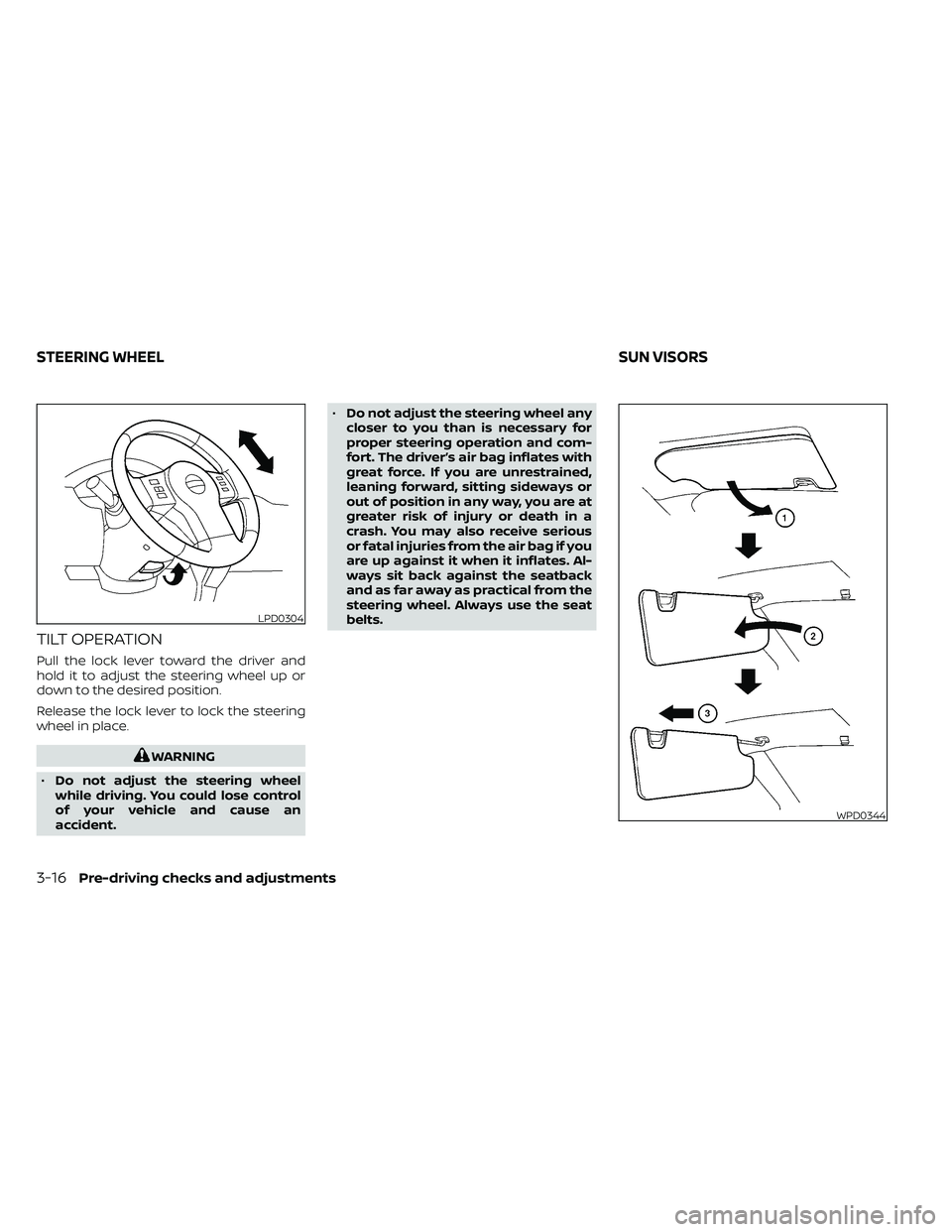
TILT OPERATION
Pull the lock lever toward the driver and
hold it to adjust the steering wheel up or
down to the desired position.
Release the lock lever to lock the steering
wheel in place.
WARNING
• Do not adjust the steering wheel
while driving. You could lose control
of your vehicle and cause an
accident. •
Do not adjust the steering wheel any
closer to you than is necessary for
proper steering operation and com-
fort. The driver’s air bag inflates with
great force. If you are unrestrained,
leaning forward, sitting sideways or
out of position in any way, you are at
greater risk of injury or death in a
crash. You may also receive serious
or fatal injuries from the air bag if you
are up against it when it inflates. Al-
ways sit back against the seatback
and as far away as practical from the
steering wheel. Always use the seat
belts.
LPD0304
WPD0344
STEERING WHEEL SUN VISORS
3-16Pre-driving checks and adjustments
Page 187 of 492
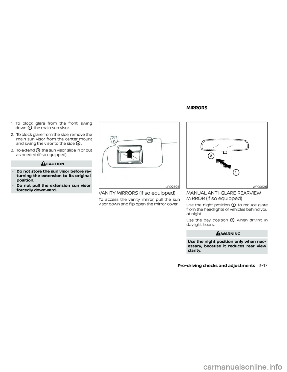
1. To block glare from the front, swingdown
O1the main sun visor.
2. To block glare from the side, remove the main sun visor from the center mount
and swing the visor to the side
O2.
3. To extend
O3the sun visor, slide in or out
as needed (if so equipped).
CAUTION
• Do not store the sun visor before re-
turning the extension to its original
position.
• Do not pull the extension sun visor
forcedly downward.
VANITY MIRRORS (if so equipped)
To access the vanity mirror, pull the sun
visor down and flip open the mirror cover.
MANUAL ANTI-GLARE REARVIEW
MIRROR (if so equipped)
Use the night positionO1to reduce glare
from the headlights of vehicles behind you
at night.
Use the day position
O2when driving in
daylight hours.
WARNING
Use the night position only when nec-
essary, because it reduces rear view
clarity.
LPD2595WPD0126
MIRRORS
Pre-driving checks and adjustments3-17
Page 188 of 492
AUTOMATIC ANTI-GLARE
REARVIEW MIRROR
The inside mirror is designed so that it au-
tomatically dims during nighttime condi-
tions and according to the intensity of the
headlights of the vehicle following you. The
automatic anti-glare feature is activated
when the ignition switch is in the ON posi-
tion.
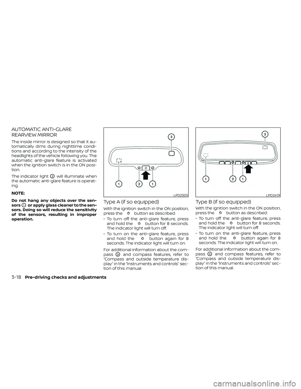
The indicator light
O2will illuminate when
the automatic anti-glare feature is operat-
ing.
NOTE:
Do not hang any objects over the sen-
sors
O1or apply glass cleaner to the sen-
sors. Doing so will reduce the sensitivity
of the sensors, resulting in improper
operation.Type A (if so equipped)
With the ignition switch in the ON position,
press thebutton as described:
• To turn off the anti-glare feature, press and hold the
button for 8 seconds.
The indicator light will turn off.
• To turn on the anti-glare feature, press and hold the
button again for 8
seconds. The indicator light will turn on.
For additional information about the com-
pass
O3and compass features, refer to
“Compass and outside temperature dis-
play” in the “Instruments and controls” sec-
tion of this manual.
Type B (if so equipped)
With the ignition switch in the ON position,
press thebutton as described:
• To turn off the anti-glare feature, press and hold the
button for 8 seconds.
The indicator light will turn off.
• To turn on the anti-glare feature, press and hold the
button again for 8
seconds. The indicator light will turn on.
For additional information about the com-
pass
O3and compass features, refer to
“Compass and outside temperature dis-
play” in the “Instruments and controls” sec-
tion of this manual.
LPD2505LPD2419
3-18Pre-driving checks and adjustments
Page 189 of 492
For additional information on HomeLink®
Universal Transceiver operation, refer to
the “HomeLink® Universal Transceiver” in
the “Instruments and controls” section of
this manual.
OUTSIDE MIRRORS
WARNING
• Objects viewed in the outside mirror
on the passenger side are closer than
they appear. Be careful when moving
to the right. Using only this mirror
could cause an accident. Use the in-
side mirror or glance over your
shoulder to properly judge distances
to other objects.
• Do not adjust the mirrors while driv-
ing. You could lose control of your ve-
hicle and cause an accident.
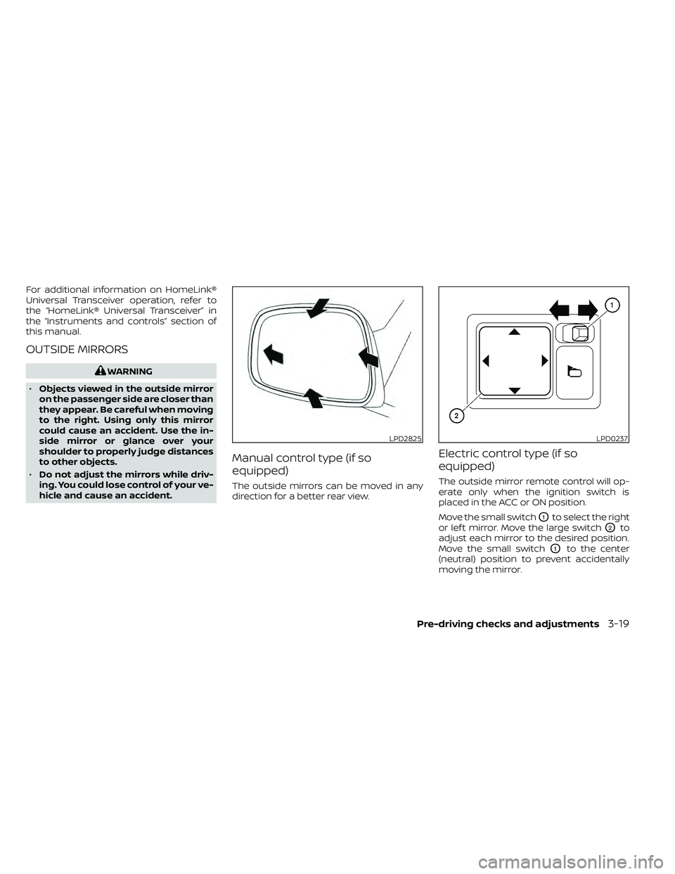
Manual control type (if so
equipped)
The outside mirrors can be moved in any
direction for a better rear view.
Electric control type (if so
equipped)
The outside mirror remote control will op-
erate only when the ignition switch is
placed in the ACC or ON position.
Move the small switch
O1to select the right
or lef t mirror. Move the large switch
O2to
adjust each mirror to the desired position.
Move the small switch
O1to the center
(neutral) position to prevent accidentally
moving the mirror.
LPD2825LPD0237
Pre-driving checks and adjustments3-19
Page 190 of 492
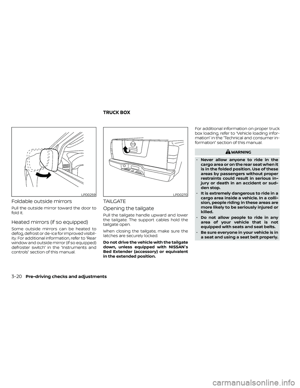
Foldable outside mirrors
Pull the outside mirror toward the door to
fold it.
Heated mirrors (if so equipped)
Some outside mirrors can be heated to
defog, defrost or de-ice for improved visibil-
ity. For additional information, refer to “Rear
window and outside mirror (if so equipped)
defroster switch” in the “Instruments and
controls” section of this manual.
TAILGATE
Opening the tailgate
Pull the tailgate handle upward and lower
the tailgate. The support cables hold the
tailgate open.
When closing the tailgate, make sure the
latches are securely locked.
Do not drive the vehicle with the tailgate
down, unless equipped with NISSAN's
Bed Extender (accessory) or equivalent
in the extended position.For additional information on proper truck
box loading, refer to “Vehicle loading infor-
mation” in the “Technical and consumer in-
formation” section of this manual.
WARNING
• Never allow anyone to ride in the
cargo area or on the rear seat when it
is in the folded position. Use of these
areas by passengers without proper
restraints could result in serious in-
jury or death in an accident or sud-
den stop.
• It is extremely dangerous to ride in a
cargo area inside a vehicle. In a colli-
sion, people riding in these areas are
more likely to be seriously injured or
killed.
• Do not allow people to ride in any
area of your vehicle that is not
equipped with seats and seat belts.
• Be sure everyone in your vehicle is in
a seat and using a seat belt properly.
LPD0259LPD0270
TRUCK BOX
3-20Pre-driving checks and adjustments