brakes NISSAN FRONTIER 2021 Owners Manual
[x] Cancel search | Manufacturer: NISSAN, Model Year: 2021, Model line: FRONTIER, Model: NISSAN FRONTIER 2021Pages: 492, PDF Size: 2.86 MB
Page 134 of 492
You cannot move the transfer 4WD shif t
switch between 4H and 4LO unless you
stop the vehicle and move the shif t lever to
the N (Neutral) position with the brake
pedal depressed.
Turn signal/hazard
indicator lights
The appropriate light flashes when the turn
signal switch is activated.
NOTE:
In case of turn signal light bulb malfunc-
tion, the turn signal will flash at a higher
frequency when the turn signal switch is
activated.
Both lights flash when the hazard switch is
turned on.
Vehicle Dynamic Control
(VDC) OFF indicator light
This indicator light comes on when the
VDC OFF switch is pushed to the OFF posi-
tion, the transfer case is in the 4LO position
(
model), or when the VDC system is
not functioning properly. This indicates the
VDC system is not operating.
Push the VDC OFF switch again or restart
the engine and the system will operate normally. For additional information, refer
to “Vehicle Dynamic Control (VDC) system”
in the “Starting and driving” section of this
manual.
The VDC light also comes on when the
push-button ignition switch is in the ON
position. The light will turn off af ter about 2
seconds if the system is operational. If the
light stays on or comes on along with the
indicator light while you are driving,
have the VDC system checked. It is recom-
mended that you visit a NISSAN dealer for
this service.
If the battery is removed or discharged, the
VDC system is disabled and the VDC indi-
cator light will not turn off af ter 2 seconds
when the ignition switch is placed in the ON
position. To reset the system, you must
perform the reset procedure. For addi-
tional information, refer to “Vehicle Dy-
namic Control (VDC) system” in the “Start-
ing and driving” section of this manual.
If the light does not go off af ter performing
the reset procedure, have the traction con-
trol system checked. It is recommended that
you visit a NISSAN dealer for this service.
While the VDC system is operating, you
might feel slight vibration or hear the sys-
tem working when starting the vehicle or
accelerating, but this is normal. The VDC system will be disabled and the
VDC light will illuminate when the elec-
tronic locking rear differential (E-lock) sys-
tem switch (if so equipped) is turned on
and the E-lock system is engaged. If the
E-lock system disengages or the switch is
turned off, the VDC system will be enabled
and the VDC light will turn off.
AUDIBLE REMINDERS
Brake pad wear warning
The disc brake pads have audible wear
warnings. When a disc brake pad requires
replacement, it makes a high pitched
scraping sound when the vehicle is in mo-
tion, whether or not the brake pedal is de-
pressed. Have the brakes checked as soon
as possible if the warning sound is heard.
Light reminder chime
With the ignition switch placed in the OFF
position, a chime sounds when the driver's
door is opened if the headlights or parking
lights are on.
Turn the headlight control switch off before
leaving the vehicle.
2-24Instruments and controls
Page 147 of 492
•The hill descent control may not con-
trol the vehicle speed on a hill under
all load or road conditions. Always be
prepared to depress the brake pedal
to control vehicle speed. Failure to do
so may result in a collision or serious
personal injury.
CAUTION
When the hill descent control system op-
erates continuously for a long time, the
temperature of the brake pads may in-
crease and the hill descent control sys-
tem may be temporarily disabled (the in-
dicator light will blink). If the indicator
light does not come on continuously af-
ter blinking, stop using the system.
The hill descent control system is designed
to reduce driver workload when going down
steep hills. The hill descent control system
helps to control vehicle speed so the driver
can concentrate on steering the vehicle.
To activate the hill descent control system:
• The shif t lever must be in forward or re- verse gear,
• The 4WD switch must be in the 4L posi- tion and the vehicle speed must be under
15 mph (25 km/h) or • The 4WD switch must be in the 4H posi-
tion and the vehicle speed must be under
21 mph (35 km/h), and
• The hill descent control system switch must be ON.
The hill descent control system ON indica-
tor light will come on when the system is
activated. Also, the stop/tail lights illumi-
nate while the hill descent control system
applies the brakes to control vehicle speed.
If the accelerator or brake pedal is depressed
while the hill descent control system is on,
the system will stop operating temporarily.
As soon as the accelerator or brake pedal is
released, the hill descent control system be-
gins to function again if the hill descent con-
trol operating conditions are fulfilled.
The hill descent control system ON indica-
tor light blinks if the switch is on and all
conditions for system activation are not
met or if the system becomes disengaged
for any reason.
To turn off the hill descent control system,
push the switch to the OFF position.
For additional information, refer to “Hill de-
scent control system ON indicator light” in
this section and “Hill descent control sys-
tem” in the “Starting and driving” section of
this manual. The E-Lock system can help provide added
traction if the vehicle is stuck or becoming
stuck.
To activate the E-Lock system:
• The 4WD switch must be in the 4LO posi-
tion (4-Wheel Drive vehicles),
• The vehicle must be stopped or moving at 4 mph (7 km/h) or less, and
• The E-Lock system switch must be turned on.
LIC0729
ELECTRONIC LOCKING REAR
DIFFERENTIAL (E-Lock) SYSTEM
SWITCH (if so equipped)
Instruments and controls2-37
Page 315 of 492
Seat belts help reduce the risk of injury in
collisions and rollovers.In a rollover crash,
an unbelted person is significantly more
likely to die than a person wearing a seat
belt..
OFF-ROAD RECOVERY
While driving, the right side or lef t side
wheels may unintentionally leave the road
surface. If this occurs, maintain control of
the vehicle by following the procedure be-
low. Please note that this procedure is only
a general guide. The vehicle must be driven
as appropriate based on the conditions of
the vehicle, road and traffic.
1. Remain calm and do not overreact.
2. Do not apply the brakes.
3. Maintain a firm grip on the steering wheel with both hands and try to hold a
straight course.
4. When appropriate, slowly release the ac- celerator pedal to gradually slow the
vehicle.
5. If there is nothing in the way, steer the vehicle to follow the road while vehicle
speed is reduced. Do not attempt to
drive the vehicle back onto the road sur-
face until vehicle speed is reduced. 6. When it is safe to do so, gradually turn
the steering wheel until both tires return
to the road surface. When all tires are on
the road surface, steer the vehicle to
stay in the appropriate driving lane.
• If you decide that it is not safe to return the vehicle to the road surface based
on vehicle, road or traffic conditions,
gradually slow the vehicle to a stop in
a safe place off the road.
RAPID AIR PRESSURE LOSS
Rapid air pressure loss or a “blow-out” can
occur if the tire is punctured or is damaged
due to hitting a curb or pothole. Rapid air
pressure loss can also be caused by driving
on under-inflated tires.
Rapid air pressure loss can affect the han-
dling and stability of the vehicle, especially
at highway speeds.
Help prevent rapid air pressure loss by
maintaining the correct air pressure and
visually inspecting the tires for wear and
damage. For additional information, refer
to “Wheels and tires” in the “Do-it-yourself ”
section of this manual. If a tire rapidly loses
air pressure or “blows-out” while driving,
maintain control of the vehicle by following
the procedure below. Please note that this
procedure is only a general guide. The ve- hicle must be driven as appropriate based
on the conditions of the vehicle, road and
traffic.
Page 317 of 492
•If your engine stalls or you cannot
make it to the top of a steep hill,
never attempt to turn around. Your
vehicle could tip or roll over. Always
back straight down in R (Reverse)
gear. Never back down in N (Neutral),
using only the brake, as this could
cause loss of control.
• Heavy braking going down a hill
could cause your brakes to overheat
and fade, resulting in loss of control
and an accident. Apply brakes lightly
and use a low gear to control your
speed. Use the hill descent control
feature (if so equipped).
• Unsecured cargo can be thrown
around when driving over rough ter-
rain. Properly secure all cargo so it
will not be thrown forward and cause
injury to you or your passengers.
• To avoid raising the center of gravity
excessively, do not exceed the rated
capacity of the roof rack (if so
equipped) and evenly distribute the
load. Secure heavy loads in the cargo
area as far forward and as low as
possible. Do not equip the vehicle
with tires larger than specified in this
manual. This could cause your ve-
hicle to roll over. •
Do not grip the inside or spokes of
the steering wheel when driving off-
road. The steering wheel could move
suddenly and injure your hands. In-
stead drive with your fingers and
thumbs on the outside of the rim.
• Before operating the vehicle, ensure
that the driver and all passengers
have their seat belts fastened.
• Always drive with the floor mats in
place as the floor may become hot.
• Lower your speed when encounter-
ing strong crosswinds. With a higher
center of gravity, your NISSAN is more
affected by strong side winds. Slower
speeds ensure better vehicle control.
• Do not drive beyond the perfor-
mance capability of the tires, even
with 4WD engaged (if so equipped).
• For 4WD equipped vehicles, do not
attempt to raise two wheels off the
ground and shif t the transmission to
any drive or reverse position with the
engine running. Doing so may result
in drivetrain damage or unexpected
vehicle movement which could result
in serious vehicle damage or per-
sonal injury. •
Do not attempt to test a 4WD
equipped vehicle on a 2-wheel dyna-
mometer (such as the dynamom-
eters used by some states for emis-
sions testing), or similar equipment
even if the other two wheels are
raised off the ground. Make sure you
inform test facility personnel that
your vehicle is equipped with 4WD
before it is placed on a dynamom-
eter. Using the wrong test equipment
may result in drivetrain damage or
unexpected vehicle movement
which could result in serious vehicle
damage or personal injury.
• Accelerating quickly, sharp steering
maneuvers or sudden braking may
cause loss of control.
• If at all possible, avoid sharp turning
maneuvers, particularly at high
speeds. Your NISSAN 4WD vehicle has
a higher center of gravity than a pas-
senger car. The vehicle is not de-
signed for cornering at the same
speeds as passenger cars. Failure to
operate this vehicle correctly could
result in loss of control and/or a roll-
over accident.
Starting and driving5-9
Page 318 of 492
•Always use tires of the same type,
size, brand, construction (bias, bias-
belted, or radial), and tread pattern
on all four wheels. Install tire chains
on the rear wheels when driving on
slippery roads and drive carefully.
• Be sure to check the brakes immedi-
ately af ter driving in mud or water.
For additional information, refer to
“Wet brakes” in this section.
• Avoid parking your vehicle on steep
hills. If you get out of the vehicle and
it rolls forward, backward or side-
ways, you could be injured.
• Whenever you drive off-road through
sand, mud or water as deep as the
wheel hub, more frequent mainte-
nance may be required. For addi-
tional information, refer to “Mainte-
nance under severe operating
conditions” in the “Maintenance and
schedules” section of this manual.
WARNING
Do not operate the push-button igni-
tion switch while driving the vehicle ex-
cept in an emergency. (The engine will
stop when the ignition switch is pushed
three consecutive times in quick suc-
cession or the ignition switch is pushed
and held for more than 2 seconds.) If
the engine stops while the vehicle is
being driven, this could lead to a crash
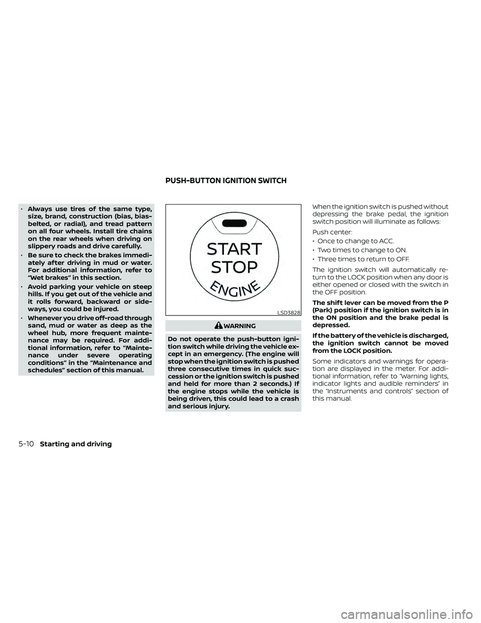
and serious injury. When the ignition switch is pushed without
depressing the brake pedal, the ignition
switch position will illuminate as follows:
Push center:
• Once to change to ACC.
• Two times to change to ON.
• Three times to return to OFF.
The ignition switch will automatically re-
turn to the LOCK position when any door is
either opened or closed with the switch in
the OFF position.
The shif t lever can be moved from the P
(Park) position if the ignition switch is in
the ON position and the brake pedal is
depressed.
If the battery of the vehicle is discharged,
the ignition switch cannot be moved
from the LOCK position.
Some indicators and warnings for opera-
tion are displayed in the meter. For addi-
tional information, refer to “Warning lights,
indicator lights and audible reminders” in
the “Instruments and controls” section of
this manual.
LSD3828
PUSH-BUTTON IGNITION SWITCH
Page 342 of 492
Normal operation
The Anti-lock Braking System (ABS) oper-
ates at speeds above3-6mph(5-10
km/h). The speed varies according to road
conditions.
When the ABS senses that one or more
wheels are close to locking up, the actuator
rapidly applies and releases hydraulic pres-
sure. This action is similar to pumping the
brakes very quickly. You may feel a pulsa-
tion in the brake pedal and hear a noise
from under the hood or feel a vibration
from the actuator when it is operating. This
is normal and indicates that the ABS is op-
erating properly. However, the pulsation
may indicate that road conditions are haz-
ardous and extra care is required while
driving. • The ABLS system uses automatic brak-
ing to transfer power from a slipping drive
wheel to the wheel on the same axle with
more traction. The ABLS system applies
braking to the slipping wheel, which helps
redirect power to the other wheel.
• On 4–Wheel Drive models the ABLS sys- tem operates in both 4H and 4LO modes.
If 4WD mode is engaged, the ABLS sys-
tem operates for both drive axles. On
2–Wheel Drive vehicles, the ABLS system
operates on the drive axle only.
• The ABLS system is always on. In some conditions, the system may automati-
cally turn the ABLS system off. If the sys-
tem is automatically turned off, normal
brake function will continue. ABLS will
function even when the Vehicle Dynamic
Control system is turned off.
• The ABLS does not operate if both wheels on a drive axle are slipping.
Page 345 of 492
•If brake related parts such as brake
pads, rotors and calipers are not
NISSAN recommended or are ex-
tremely deteriorated, the VDC sys-
tem may not operate properly and
both the
and theindicator
lights may illuminate.
• If engine control related parts are not
NISSAN recommended or are ex-
tremely deteriorated, both the
andindicator lights may
illuminate.
• When driving on extremely inclined
surfaces such as higher banked cor-
ners, the VDC system may not oper-
ate properly and the
indicator
light may flash or theindicator
light may illuminate. Do not drive on
these types of roads.
• When driving on an unstable surface
such as a turntable, ferry, elevator or
ramp, the
indicator light may
flash or theindicator light may
illuminate. This is not a malfunction.
Restart the engine af ter driving onto
a stable surface. •
If wheels or tires other than the
NISSAN recommended ones are
used, the VDC system may not oper-
ate properly and the
indicator
light may flash or theindicator
light may illuminate.
• The VDC system is not a substitute
for winter tires or tire chains on a
snow covered road.
WARNING
• Never rely solely on the hill descent
control system to control vehicle
speed when driving on steep down-
hill grades. Always drive carefully and
attentively when using the hill de-
scent control system and decelerate
the vehicle speed by depressing the
brake pedal if necessary. Be espe-
cially careful when driving on frozen,
muddy or extremely steep downhill
roads. Failure to control vehicle
speed may result in a loss of control
of the vehicle and possible serious
injury or death.
• The hill descent control may not con-
trol the vehicle speed on a hill under
all load or road conditions. Always be
prepared to depress the brake pedal
to control vehicle speed. Failure to do
so may result in a collision or serious
personal injury.
The hill descent control system helps
maintain vehicle speed when driving under
15-21 mph (25-35 km/h) on steeper down-
hill grades. Hill descent control is useful
when engine braking alone in 4H or 4L can-
not control vehicle speed. Hill descent con-
trol applies the vehicle brakes to control
HILL DESCENT CONTROL SYSTEM (if
so equipped)
Starting and driving5-37
Page 396 of 492
If the brakes do not operate properly, have
the brakes checked. It is recommended
that you visit a NISSAN dealer for this ser-
vice.
Self-adjusting brakes
Your vehicle is equipped with self-adjusting
brakes.
The front and rear disc-type brakes self-
adjust every time the brake pedal is ap-
plied.
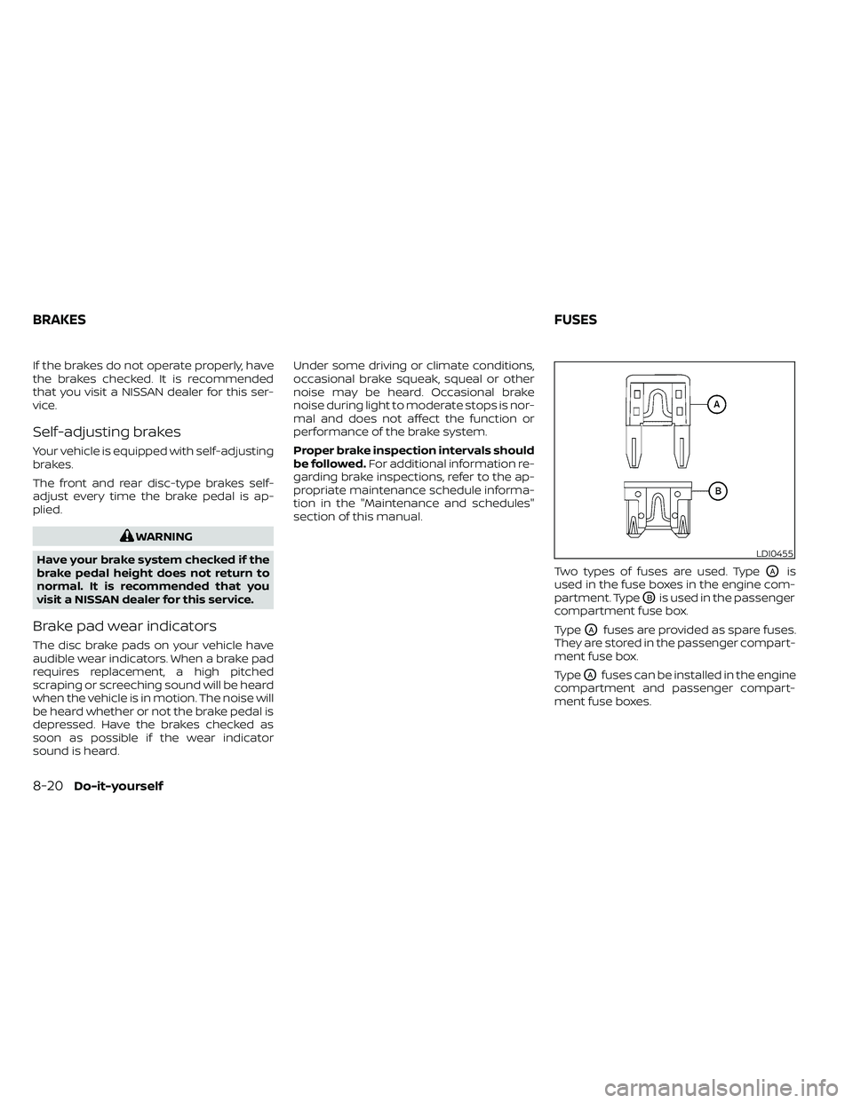
LDI0455
BRAKESFUSES
Page 421 of 492
secondary latch keeps the hood from
opening when the primary latch is re-
leased.
When driving in areas using road salt or
other corrosive materials, check lubrica-
tion frequently.
Lights*:Clean the headlights on a regular
basis. Make sure that the headlights, stop
lights, tail lights, turn signal lights, and other
lights are all operating properly and in-
stalled securely. Also check headlight aim.
Road wheel nuts (lug nuts)*: When check-
ing the tires, make sure no wheel nuts are
missing, and check for any loose wheel
nuts. Tighten if necessary.
Tire rotation*: Tires should be rotated ev-
ery 7,500 miles (12,000 km).
Tires*: Check the pressure with a gauge
of ten and always prior to long distance
trips. If necessary, adjust the pressure in all
tires, including the spare, to the pressure
specified. Check carefully for damage, cuts
or excessive wear.
Tire Pressure Monitoring System (TPMS)
transmitter components: Replace the
TPMS transmitter grommet seal, valve core
and cap when the tires are replaced due to
wear or age. Wheel alignment and balance:
If the ve-
hicle should pull to either side while driving
on a straight and level road, or if you detect
uneven or abnormal tire wear, there may
be a need for wheel alignment. If the steer-
ing wheel or seat vibrates at normal high-
way speeds, wheel balancing may be
needed.
For additional information regarding tires,
refer to “Important Tire Safety Information”
(US) or “Tire Safety Information” (Canada) in
the Warranty Information Booklet.
Windshield: Clean the windshield on a
regular basis. Check the windshield at least
every six months for cracks or other dam-
age. Have a damaged windshield repaired
by a qualified repair facility. It is recom-
mended that you have a damaged wind-
shield repaired by a NISSAN dealer, or a
NISSAN Certified Collision Center. To locate
a collision center in your area, refer to
http://collision.nissanusa.com.
Windshield wiper blades*: Check for
cracks or wear if they do not wipe properly.Inside the vehicle
The maintenance items listed here should
be checked on a regular basis, such as
when performing scheduled maintenance,
cleaning the vehicle, etc.
Accelerator pedal:
Check the pedal for
smooth operation and make sure the pedal
does not catch or require uneven effort.
Keep the floor mat away from the pedal.
Automatic transmission P (Park) mecha-
nism: On a fairly steep hill check that the
vehicle is held securely with the shif t lever
in the P (Park) position without applying any
brakes.
Brake pedal: Check the pedal for smooth
operation. If the brake pedal suddenly goes
down further than normal, the pedal feels
spongy or the vehicle seems to take longer
to stop, have your vehicle checked imme-
diately. It is recommended that you visit a
NISSAN dealer for this service. Keep the
floor mat away from the pedal.
Brakes: Check that the brakes do not pull
the vehicle to one side when applied.
Parking brake: Check the parking brake
operation regularly. The vehicle should be
securely held on a fairly steep hill with only
the parking brake applied. If the parking
Maintenance and schedules9-3
Page 465 of 492
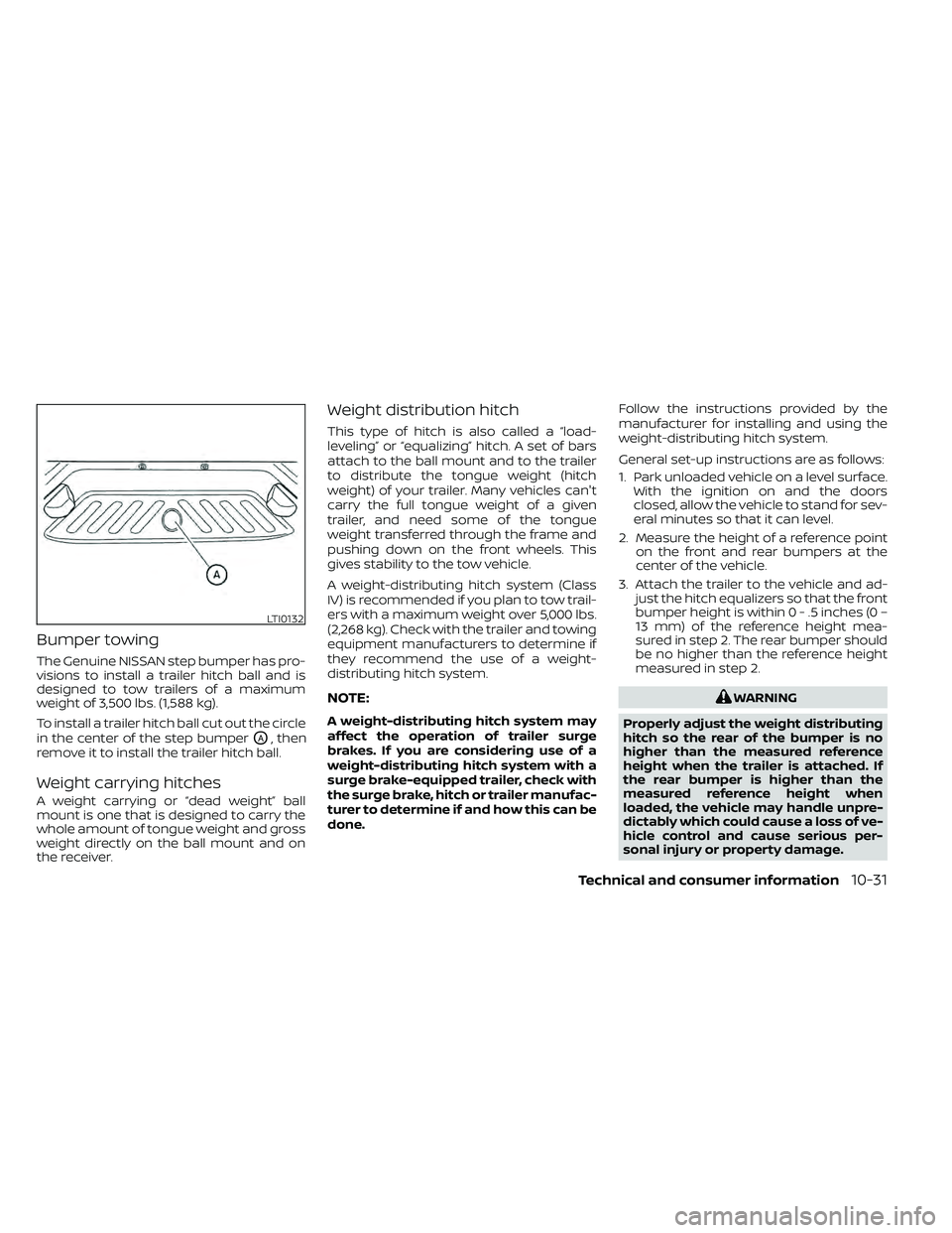
Bumper towing
The Genuine NISSAN step bumper has pro-
visions to install a trailer hitch ball and is
designed to tow trailers of a maximum
weight of 3,500 lbs. (1,588 kg).
To install a trailer hitch ball cut out the circle
in the center of the step bumper
OA, then
remove it to install the trailer hitch ball.
Weight carrying hitches
A weight carrying or “dead weight” ball
mount is one that is designed to carry the
whole amount of tongue weight and gross
weight directly on the ball mount and on
the receiver.
Weight distribution hitch
This type of hitch is also called a “load-
leveling” or “equalizing” hitch. A set of bars
attach to the ball mount and to the trailer
to distribute the tongue weight (hitch
weight) of your trailer. Many vehicles can't
carry the full tongue weight of a given
trailer, and need some of the tongue
weight transferred through the frame and
pushing down on the front wheels. This
gives stability to the tow vehicle.
A weight-distributing hitch system (Class
IV) is recommended if you plan to tow trail-
ers with a maximum weight over 5,000 lbs.
(2,268 kg). Check with the trailer and towing
equipment manufacturers to determine if
they recommend the use of a weight-
distributing hitch system.
NOTE:
A weight-distributing hitch system may
affect the operation of trailer surge
brakes. If you are considering use of a
weight-distributing hitch system with a
surge brake-equipped trailer, check with
the surge brake, hitch or trailer manufac-
turer to determine if and how this can be
done. Follow the instructions provided by the
manufacturer for installing and using the
weight-distributing hitch system.
General set-up instructions are as follows:
1. Park unloaded vehicle on a level surface.
With the ignition on and the doors
closed, allow the vehicle to stand for sev-
eral minutes so that it can level.
2. Measure the height of a reference point on the front and rear bumpers at the
center of the vehicle.
3. Attach the trailer to the vehicle and ad- just the hitch equalizers so that the front
bumper height is within0-.5inches (0 –
13 mm) of the reference height mea-
sured in step 2. The rear bumper should
be no higher than the reference height
measured in step 2.