glove box NISSAN KICKS 2020 Owner´s Manual
[x] Cancel search | Manufacturer: NISSAN, Model Year: 2020, Model line: KICKS, Model: NISSAN KICKS 2020Pages: 500, PDF Size: 3.43 MB
Page 13 of 500
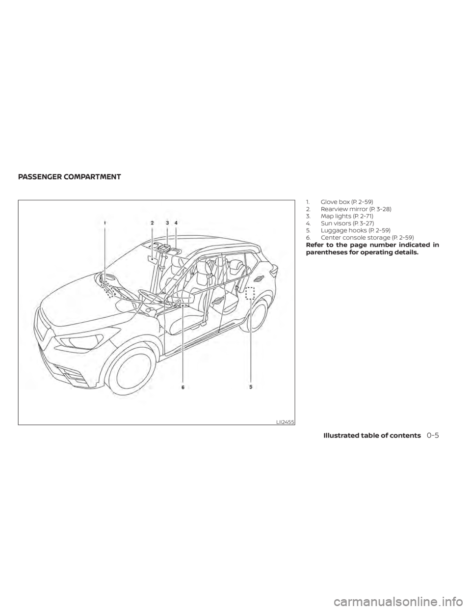
1. Glove box (P. 2-59)
2. Rearview mirror (P. 3-28)
3. Map lights (P. 2-71)
4. Sun visors (P. 3-27)
5. Luggage hooks (P. 2-59)
6. Center console storage (P. 2-59)
Refer to the page number indicated in
parentheses for operating details.
LII2455
PASSENGER COMPARTMENT
Illustrated table of contents0-5
Page 14 of 500
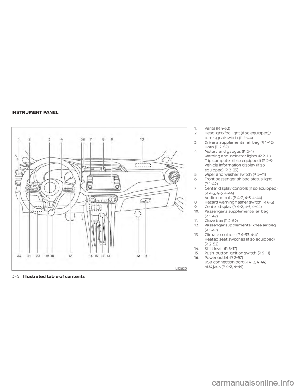
1. Vents (P. 4-32)
2. Headlight/fog light (if so equipped)/turn signal switch (P. 2-44)
3. Driver's supplemental air bag (P. 1-42) Horn (P. 2-52)
4. Meters and gauges (P. 2-4) Warning and indicator lights (P. 2-11)
Trip computer (if so equipped) (P. 2-9)
Vehicle information display (if so
equipped) (P. 2-23)
5. Wiper and washer switch (P. 2-41)
6. Front passenger air bag status light
(P. 1-42)
7. Center display controls (if so equipped)
(P. 4-2, 4-3, 4-44)
Audio controls (P. 4-2, 4-3, 4-44)
8. Hazard warning flasher switch (P. 6-2)
9. Center display (P. 4-2, 4-3, 4-44)
10. Passenger's supplemental air bag
(P. 1-42)
11. Glove box (P. 2-59)
12. Passenger supplemental knee air bag
(P. 1-42)
13. Climate controls (P. 4-33, 4-41) Heated seat switches (if so equipped)
(P. 2-52)
14. Shif t lever (P. 5-17)
15. Push-button ignition switch (P. 5-11)
16. Power outlet (P. 2-57) USB connection port (P. 4-2, 4-44)
AUX jack (P. 4-2, 4-44)
LII2620
INSTRUMENT PANEL
0-6Illustrated table of contents
Page 69 of 500
WARNING
To ensure proper operation of the pas-
senger’s NISSAN Advanced Air Bag Sys-
tem, please observe the following
items.
• Do not allow a passenger in the rear
seat to push or pull on the seatback
pocket.
• Do not place heavy loads heavier
than 9.1 lbs. (4 kg) on the seatback,
head restraint/headrest or in the
seatback pocket.
• Make sure that there is nothing
pressing against the rear of the seat-
back, such as a child restraint in-
stalled in the rear seat or an object
stored on the floor.
• Make sure that there is no object
placed under the front passenger
seat.
• Make sure that there is no object
placed between the seat cushion and
center console or between the seat
cushion and the door. •
If a forward-facing child restraint is
installed in the front passenger seat,
do not position the front passenger
seat so the child restraint contacts
the instrument panel. If the child re-
straint does contact the instrument
panel, the system may determine the
seat is occupied and the passenger
air bag may deploy in a collision. Also
the front passenger air bag status
light may not illuminate. For addi-
tional information, refer to “Child re-
straints” in this section.
• Confirm the operating condition with
the front passenger air bag status
light.
• If you notice that the front passenger
air bag status light is not operating
as described later in this section, get
the occupant classification system
checked. It is recommended that you
visit a NISSAN dealer for this service.
• Until you have confirmed with a
dealer that your front passenger seat
occupant classification system is
working properly, position the occu-
pants in the rear seating positions. •
Do not position the front passenger
seat so it contacts the rear seat. If the
front seat does contact the rear seat,
the air bag system may determine a
sensor malfunction has occurred
and the front passenger air bag sta-
tus light may illuminate and the
supplemental air bag warning light
may flash.
This vehicle is equipped with the NISSAN
Advanced Air Bag System for the driver and
front passenger seats. This system is de-
signed to meet certification requirements
under U.S. regulations. It is also permitted in
Canada. All of the information, cautions
and warnings in this manual still apply
and must be followed.
The driver supplemental front-impact air
bag is located in the center of the steering
wheel. The front passenger supplemental
front-impact air bag is mounted in the dash-
board above the glove box. The front air bags
are designed to inflate in higher severity
frontal collisions, although they may inflate if
the forces in another type of collision are
similar to those of a higher severity frontal
impact. They may not inflate in certain fron-
tal collisions. Vehicle damage (or lack of it) is
not always an indication of proper front air
bag system operation.
Safety-Seats, seat belts and supplemental restraint system1-49
Page 85 of 500
12v outlets.................................. 2-57
Extended storage switch .......................2-58
Storage ........................................ 2-59
Front-door pockets ......................... 2-59
Rear-door pockets (if so equipped) ..........2-59
Seatback pockets (if so equipped) ...........2-60
Storagetrays................................ 2-60
Glovebox ................................... 2-61
Cup holders ................................. 2-62
Luggage hooks ............................. 2-63Grocery hooks
.............................. 2-63
Cargo cover (if so equipped) .................2-64
Roof rack (if so equipped) ...................2-65
Windows ....................................... 2-68
Power windows ............................. 2-68
Interior lights ................................... 2-71
Map lights ................................... 2-72
Personal Light ............................... 2-72
Luggage compartment light ................2-73
Page 86 of 500
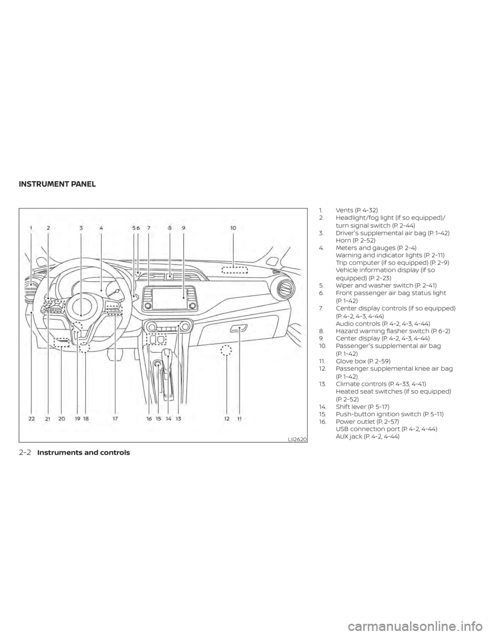
1. Vents (P. 4-32)
2. Headlight/fog light (if so equipped)/turn signal switch (P. 2-44)
3. Driver's supplemental air bag (P. 1-42) Horn (P. 2-52)
4. Meters and gauges (P. 2-4) Warning and indicator lights (P. 2-11)
Trip computer (if so equipped) (P. 2-9)
Vehicle information display (if so
equipped) (P. 2-23)
5. Wiper and washer switch (P. 2-41)
6. Front passenger air bag status light
(P. 1-42)
7. Center display controls (if so equipped)
(P. 4-2, 4-3, 4-44)
Audio controls (P. 4-2, 4-3, 4-44)
8. Hazard warning flasher switch (P. 6-2)
9. Center display (P. 4-2, 4-3, 4-44)
10. Passenger's supplemental air bag
(P. 1-42)
11. Glove box (P. 2-59)
12. Passenger supplemental knee air bag
(P. 1-42)
13. Climate controls (P. 4-33, 4-41) Heated seat switches (if so equipped)
(P. 2-52)
14. Shif t lever (P. 5-17)
15. Push-button ignition switch (P. 5-11)
16. Power outlet (P. 2-57) USB connection port (P. 4-2, 4-44)
AUX jack (P. 4-2, 4-44)
LII2620
INSTRUMENT PANEL
2-2Instruments and controls
Page 145 of 500
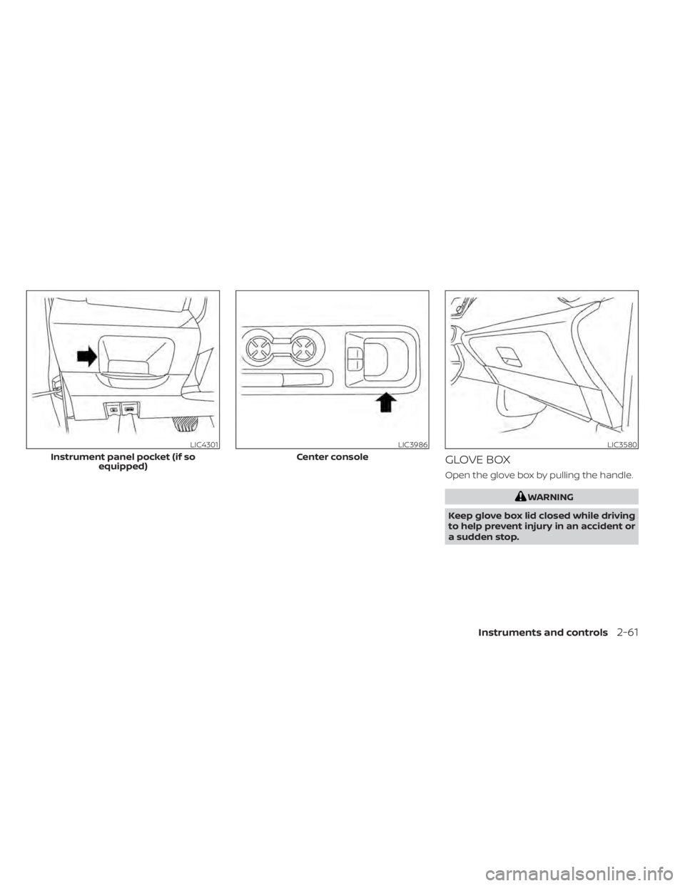
GLOVE BOX
Open the glove box by pulling the handle.
WARNING
Keep glove box lid closed while driving
to help prevent injury in an accident or
a sudden stop.
LIC4301
Instrument panel pocket (if so equipped)
LIC3986
Center console
LIC3580
Instruments and controls2-61
Page 150 of 500
Installing Crossbars (if so
equipped)
WARNING
• It is recommended that you have the
roof rack crossbars installed by a
NISSAN dealer.
• Protect the painted area on the ve-
hicle roof under the crossbars by
placing a piece of cloth under the
cross bars to prevent scratch
damage.
• Removal and re-installation of cross-
bars requires purchase of new M6
bolts (T99R1 5RL0A-S1) or the re-
application of thread-locking adhe-
sive such as LOCTITE® , 242® , or
equivalent.
• Do not attempt to adjust fasteners
on the underside of the end sup-
ports. Fasteners are pre-adjusted to
the proper torque requirement by
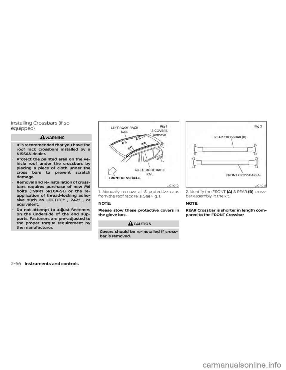
the manufacturer. 1. Manually remove all 8 protective caps
from the roof rack rails. See Fig. 1.
NOTE:
Please stow these protective covers in
the glove box.
CAUTION
Covers should be re-installed if cross-
bar is removed. 2. Identif y the FRONT
(A)& REAR (B)cross-
bar assembly in the kit.
NOTE:
REAR Crossbar is shorter in length com-
pared to the FRONT Crossbar
LIC4010LIC4011
2-66Instruments and controls
Page 169 of 500
When any door is open, the doors are
locked, and then the Intelligent Key is put
inside the vehicle and all the doors are
closed, a chime will sound and the lock will
automatically unlock.
NOTE:
The doors may not lock when the Intelli-
gent Key is in the same hand that is op-
erating the request switch (if so
equipped) to lock the door. Put the Intel-
ligent Key in a purse, pocket or your
other hand.
CAUTION
The lockout protection may not func-
tion under the following conditions:
• When the Intelligent Key is placed on
top of the instrument panel.
• When the Intelligent Key is placed in-
side the glove box or a storage bin.
• When the Intelligent Key is placed in-
side the door pockets.
• When the Intelligent Key is placed in-
side or near metallic materials.
Unlocking doors
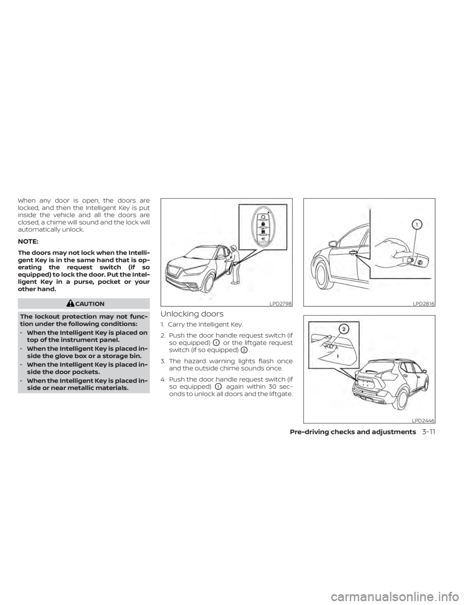
1. Carry the Intelligent Key.
2. Push the door handle request switch (if so equipped)
O1or the lif tgate request
switch (if so equipped)
O2.
3. The hazard warning lights flash once and the outside chime sounds once.
4. Push the door handle request switch (if so equipped)
O1again within 30 sec-
onds to unlock all doors and the lif tgate.
LPD2798LPD2816
LPD2446
Pre-driving checks and adjustments3-11
Page 284 of 500

Some indicators and warnings for opera-
tion are displayed on the vehicle informa-
tion display (if so equipped). For additional
information, refer to “Vehicle information
display” in the “Instruments and controls”
section of this manual.
OPERATING RANGE
The Intelligent Key functions can only be
used when the Intelligent Key is within the
specified operating range.
When the Intelligent Key battery is almost
discharged or strong radio waves are pres-
ent near the operating location, the Intelli-
gent Key system’s operating range becomes
narrower and may not function properly.
If the Intelligent Key is within the operating
range, it is possible for anyone, even some-
one who does not carry the Intelligent Key,
to push the ignition switch to start the en-
gine.The operating range of the engine start
function is inside of the vehicle
O1.
• The luggage area is not included in the operating range, but the Intelligent Key
may function.
• If the Intelligent Key is placed on the in- strument panel, inside the glove box,
storage bin or door pocket, the Intelligent
Key may not function.
• If the Intelligent Key is placed near the door or window outside the vehicle, the
Intelligent Key may function.
PUSH-BUTTON IGNITION SWITCH
POSITIONS
LOCK (Normal parking position)
The ignition switch can only be locked in
this position.
The ignition switch will be unlocked when it
is pushed to the ON position while carrying
the Intelligent Key.
The ignition switch will lock when any door
is opened or closed with the ignition
switched off.
LSD2020
5-12Starting and driving
Page 424 of 500
WARNING
• Operating the engine with the air
cleaner filter off can cause you or
others to be burned. The air cleaner
filter not only cleans the intake air, it
also stops the flame if the engine
backfires. If the air cleaner is not in-
stalled and the engine backfires, you
could be burned. Never drive with the
air cleaner filter off. Be cautious
working on the engine when the air
cleaner is off. •
Never pour fuel into the throttle body
or attempt to start the engine with
the air cleaner removed. Doing so
could result in serious injury.
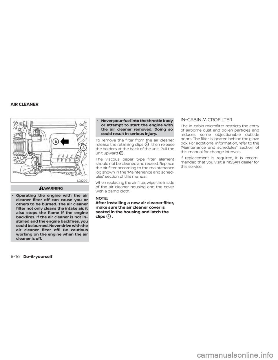
To remove the filter from the air cleaner,
release the retaining clips
OA, then release
the holders at the back of the unit. Pull the
unit upward
OB.
The viscous paper type filter element
should not be cleaned and reused. Replace
the air filter according to the maintenance
log shown in the “Maintenance and sched-
ules” section of this manual.
When replacing the air filter, wipe the inside
of the air cleaner housing and the cover
with a damp cloth.
NOTE:
Af ter installing a new air cleaner filter,
make sure the air cleaner cover is
seated in the housing and latch the
clips
OA.
IN-CABIN MICROFILTER
The in-cabin microfilter restricts the entry
of airborne dust and pollen particles and
reduces some objectionable outside
odors. The filter is located behind the glove
box. For additional information, refer to the
“Maintenance and schedules” section of
this manual for change intervals.
If replacement is required, it is recom-
mended that you visit a NISSAN dealer for
this service.
LDI2991
AIR CLEANER
8-16Do-it-yourself