NISSAN LATIO 2007 Service Repair Manual
LATIO 2007
NISSAN
NISSAN
https://www.carmanualsonline.info/img/5/57361/w960_57361-0.png
NISSAN LATIO 2007 Service Repair Manual
Trending: fuel pressure, inflation pressure, refrigerant type, radiator cap, tow, mirror, CD player
Page 2471 of 2896
TROUBLE DIAGNOSIS
MTC-59
C
D
E
F
G
H
I
K
L
MA
B
MTC
Revision: June 20062007 Versa
8. CHECK ENGINE COOLANT TEMPERATURE SENSOR
Check engine control temperature sensor. Refer to EC-200, "
DTC P0117, P0118 ECT SENSOR" .
OK or NG
OK >> System OK.
NG >> Repair or replace as necessary. Retest.
9. CHECK HEATER HOSES
Check heater hoses for proper installation.
OK or NG
OK >> GO TO 10.
NG >> Repair /replace as necessary. Retest GO TO 7.
10. BACK FLUSH HEATER CORE
1. Back flush heater core.
2. Drain the water from the system.
3. Refill system with new engine coolant. Refer to CO-8, "
Changing Engine Coolant" .
4. Start engine and warm it up to normal operating temperature.
5. Touch both the inlet and outlet heater hoses.
Is the inlet hose hot and the outlet hose warm? YES or NO
YES >> System OK.
NO >> Replace heater core and refill engine coolant. Refer to MTC-73, "
HEATER CORE" .
Page 2472 of 2896
MTC-60
TROUBLE DIAGNOSIS
Revision: June 20062007 Versa
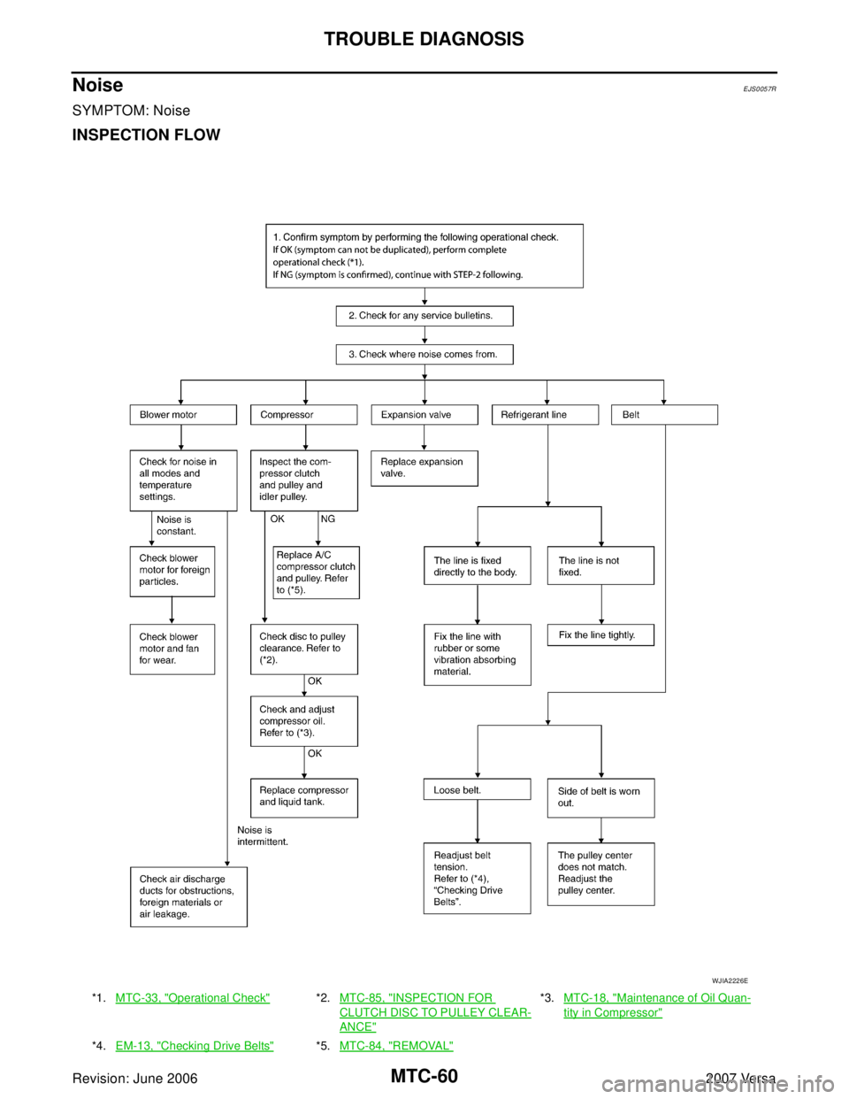
NoiseEJS0057R
SYMPTOM: Noise
INSPECTION FLOW
*1.MTC-33, "Operational Check"*2.MTC-85, "INSPECTION FOR
CLUTCH DISC TO PULLEY CLEAR-
ANCE"
*3.MTC-18, "Maintenance of Oil Quan-
tity in Compressor"
*4.EM-13, "Checking Drive Belts"*5.MTC-84, "REMOVAL"
WJIA2226E
Page 2473 of 2896
CONTROLLER
MTC-61
C
D
E
F
G
H
I
K
L
MA
B
MTC
Revision: June 20062007 Versa
CONTROLLERPFP:28074
Removal and InstallationEJS00580
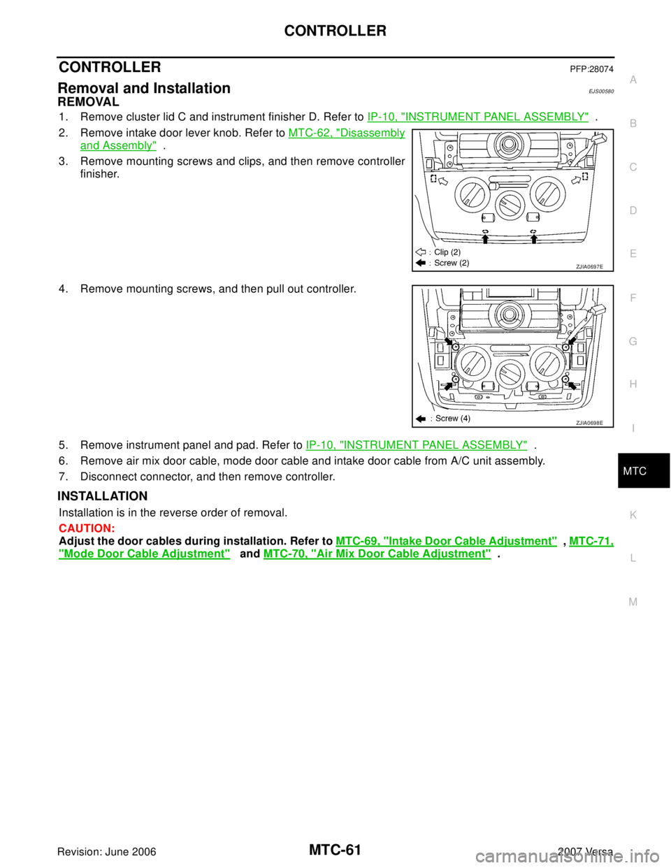
REMOVAL
1. Remove cluster lid C and instrument finisher D. Refer to IP-10, "INSTRUMENT PANEL ASSEMBLY" .
2. Remove intake door lever knob. Refer to MTC-62, "
Disassembly
and Assembly" .
3. Remove mounting screws and clips, and then remove controller
finisher.
4. Remove mounting screws, and then pull out controller.
5. Remove instrument panel and pad. Refer to IP-10, "
INSTRUMENT PANEL ASSEMBLY" .
6. Remove air mix door cable, mode door cable and intake door cable from A/C unit assembly.
7. Disconnect connector, and then remove controller.
INSTALLATION
Installation is in the reverse order of removal.
CAUTION:
Adjust the door cables during installation. Refer to MTC-69, "
Intake Door Cable Adjustment" , MTC-71,
"Mode Door Cable Adjustment" and MTC-70, "Air Mix Door Cable Adjustment" .
ZJIA0697E
ZJIA0698E
Page 2474 of 2896
MTC-62
CONTROLLER
Revision: June 20062007 Versa
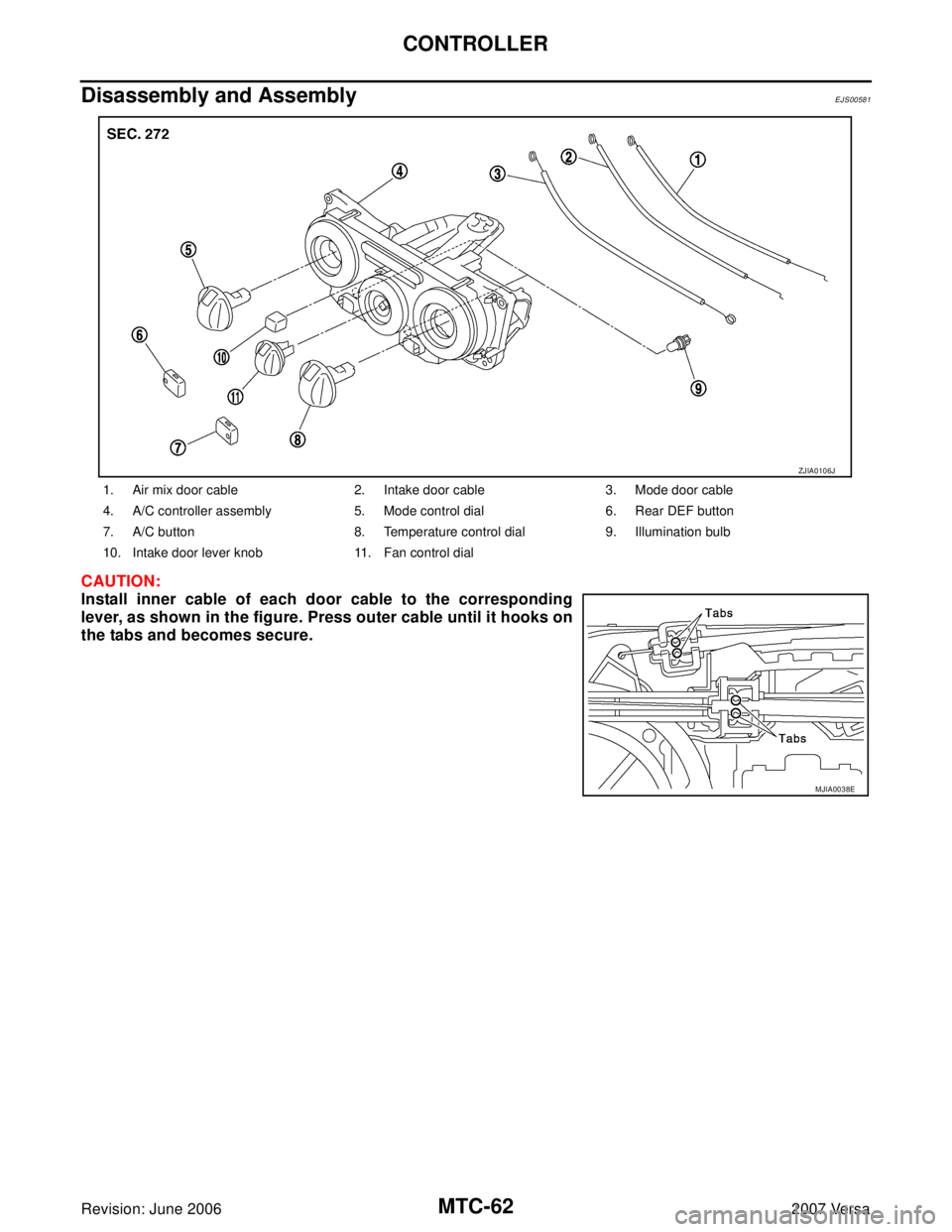
Disassembly and AssemblyEJS00581
CAUTION:
Install inner cable of each door cable to the corresponding
lever, as shown in the figure. Press outer cable until it hooks on
the tabs and becomes secure.
1. Air mix door cable 2. Intake door cable 3. Mode door cable
4. A/C controller assembly 5. Mode control dial 6. Rear DEF button
7. A/C button 8. Temperature control dial 9. Illumination bulb
10. Intake door lever knob 11. Fan control dial
ZJIA0106J
MJIA0038E
Page 2475 of 2896
THERMO CONTROL AMPLIFIER
MTC-63
C
D
E
F
G
H
I
K
L
MA
B
MTC
Revision: June 20062007 Versa
THERMO CONTROL AMPLIFIERPFP:27675
Removal and InstallationEJS00582
REMOVAL
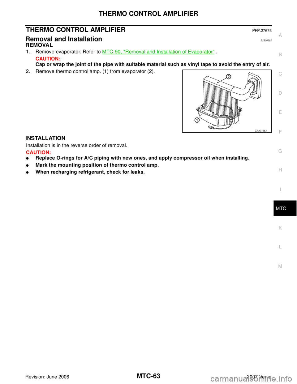
1. Remove evaporator. Refer to MTC-90, "Removal and Installation of Evaporator" .
CAUTION:
Cap or wrap the joint of the pipe with suitable material such as vinyl tape to avoid the entry of air.
2. Remove thermo control amp. (1) from evaporator (2).
INSTALLATION
Installation is in the reverse order of removal.
CAUTION:
�Replace O-rings for A/C piping with new ones, and apply compressor oil when installing.
�Mark the mounting position of thermo control amp.
�When recharging refrigerant, check for leaks.
ZJIA0798J
Page 2476 of 2896
MTC-64
A/C UNIT ASSEMBLY
Revision: June 20062007 Versa
A/C UNIT ASSEMBLYPFP:27110
Removal and InstallationEJS00583
REMOVAL
1. Use a recovery/recycling equipment (for HFC-134a) to discharge refrigerant.
2. Drain coolant from cooling system. Refer to CO-8, "
Changing Engine Coolant" .
3. Remove cowl top cover. Refer to EI-20, "
COWL TOP" .
4. Remove lower dash insulator.
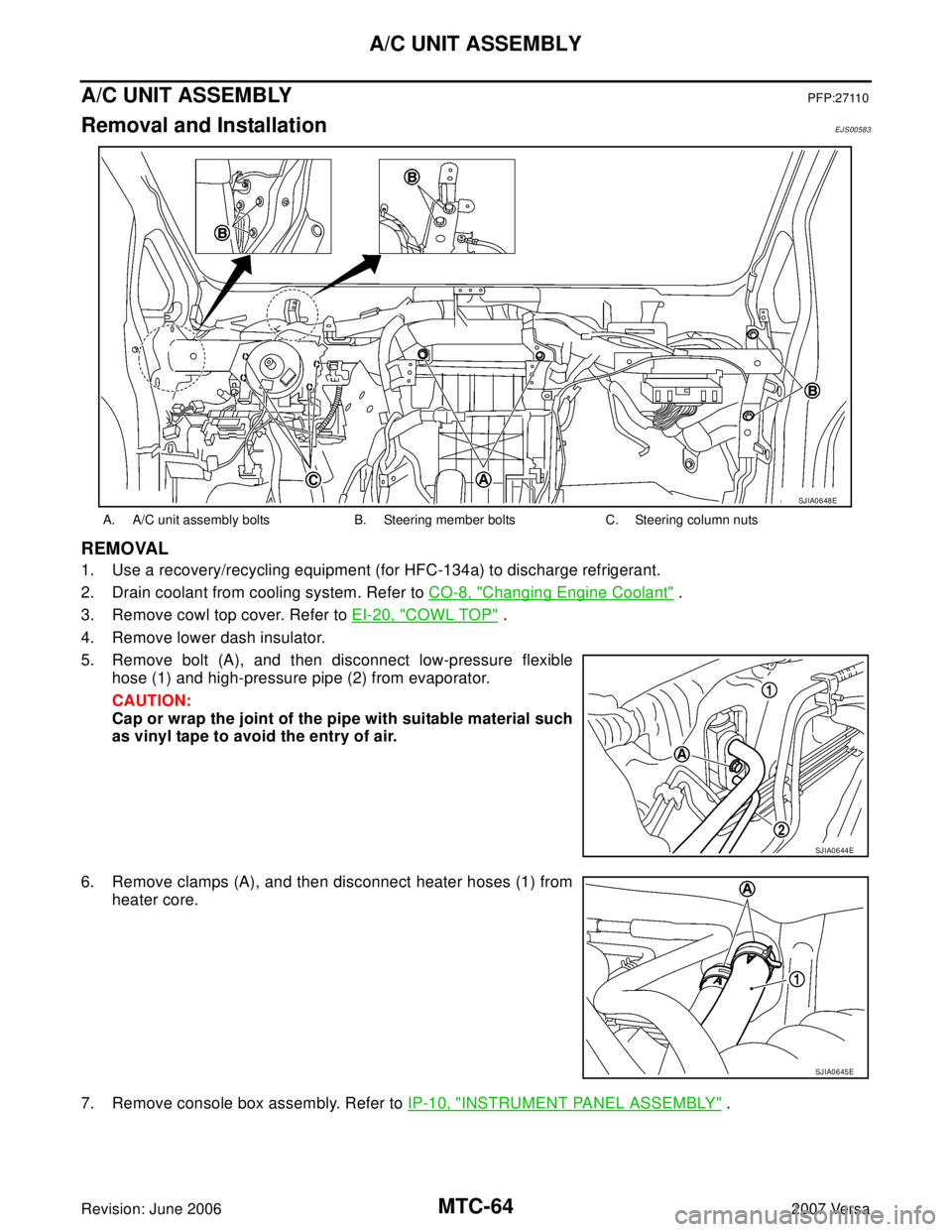
5. Remove bolt (A), and then disconnect low-pressure flexible
hose (1) and high-pressure pipe (2) from evaporator.
CAUTION:
Cap or wrap the joint of the pipe with suitable material such
as vinyl tape to avoid the entry of air.
6. Remove clamps (A), and then disconnect heater hoses (1) from
heater core.
7. Remove console box assembly. Refer to IP-10, "
INSTRUMENT PANEL ASSEMBLY" .
A. A/C unit assembly bolts B. Steering member bolts C. Steering column nuts
SJIA0648E
SJIA0644E
SJIA0645E
Page 2477 of 2896
A/C UNIT ASSEMBLY
MTC-65
C
D
E
F
G
H
I
K
L
MA
B
MTC
Revision: June 20062007 Versa
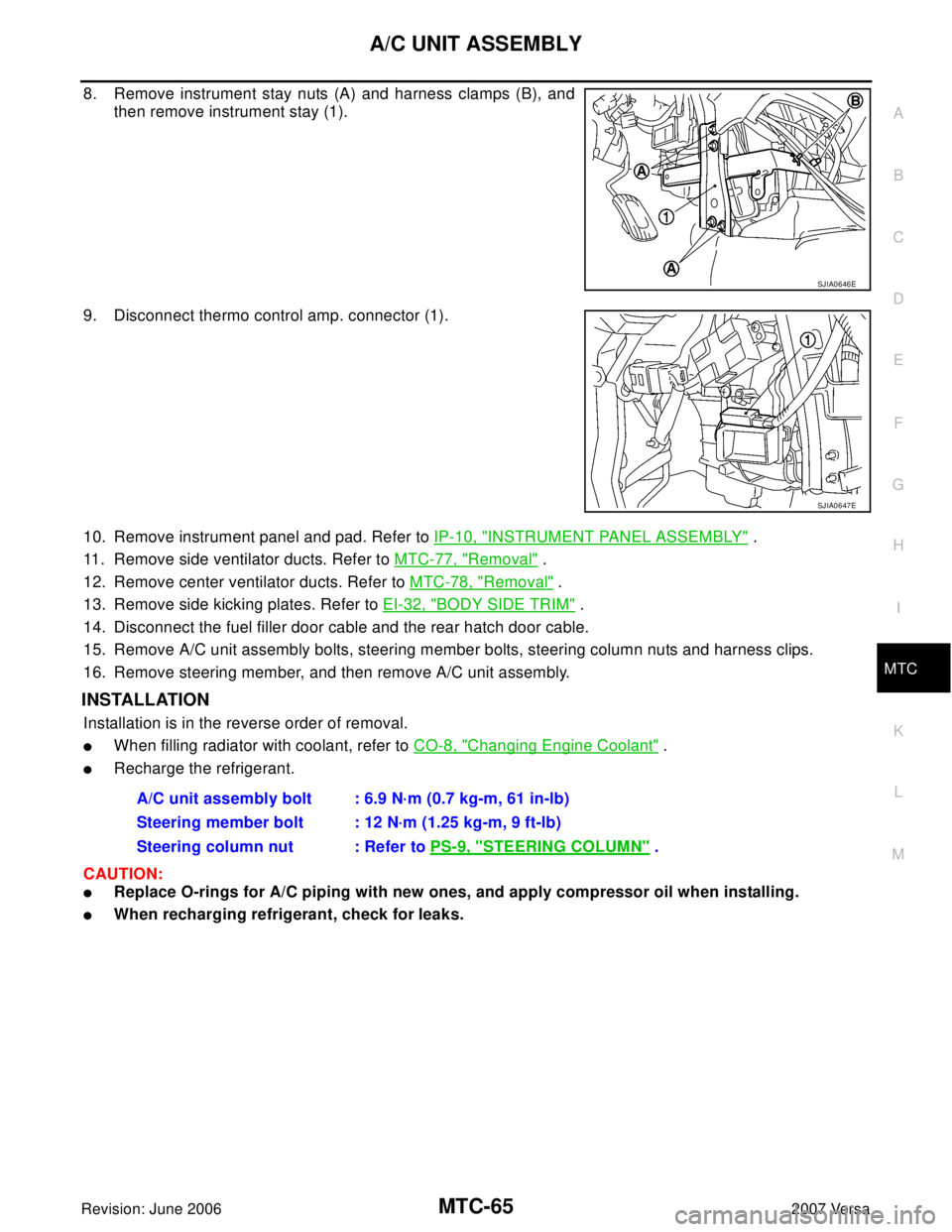
8. Remove instrument stay nuts (A) and harness clamps (B), and
then remove instrument stay (1).
9. Disconnect thermo control amp. connector (1).
10. Remove instrument panel and pad. Refer to IP-10, "
INSTRUMENT PANEL ASSEMBLY" .
11. Remove side ventilator ducts. Refer to MTC-77, "
Removal" .
12. Remove center ventilator ducts. Refer to MTC-78, "
Removal" .
13. Remove side kicking plates. Refer to EI-32, "
BODY SIDE TRIM" .
14. Disconnect the fuel filler door cable and the rear hatch door cable.
15. Remove A/C unit assembly bolts, steering member bolts, steering column nuts and harness clips.
16. Remove steering member, and then remove A/C unit assembly.
INSTALLATION
Installation is in the reverse order of removal.
�When filling radiator with coolant, refer to CO-8, "Changing Engine Coolant" .
�Recharge the refrigerant.
CAUTION:
�Replace O-rings for A/C piping with new ones, and apply compressor oil when installing.
�When recharging refrigerant, check for leaks.
SJIA0646E
SJIA0647E
A/C unit assembly bolt : 6.9 N·m (0.7 kg-m, 61 in-lb)
Steering member bolt : 12 N·m (1.25 kg-m, 9 ft-lb)
Steering column nut : Refer to PS-9, "
STEERING COLUMN" .
Page 2478 of 2896
MTC-66
A/C UNIT ASSEMBLY
Revision: June 20062007 Versa
Disassembly and AssemblyEJS00584
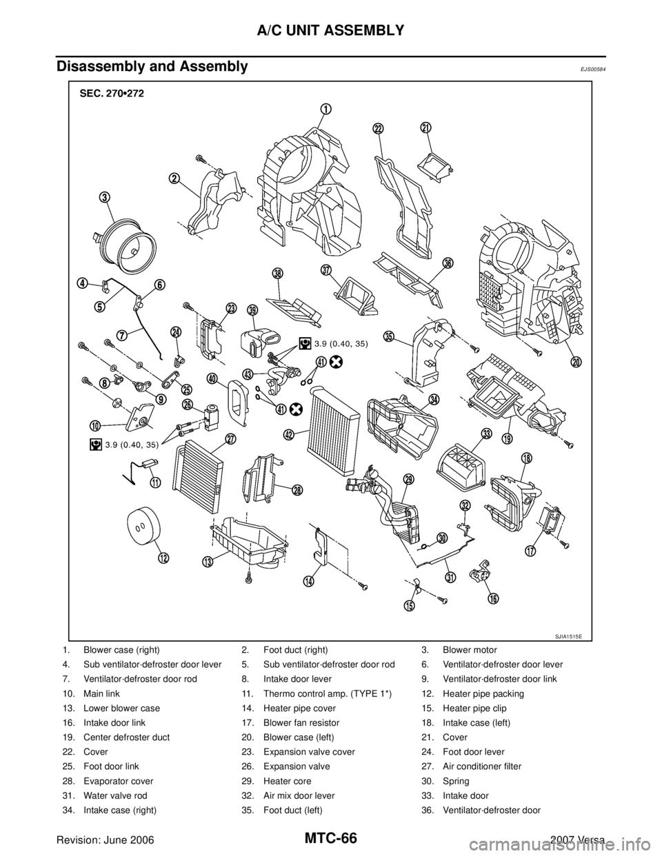
1. Blower case (right) 2. Foot duct (right) 3. Blower motor
4. Sub ventilator·defroster door lever 5. Sub ventilator·defroster door rod 6. Ventilator·defroster door lever
7. Ventilator·defroster door rod 8. Intake door lever 9. Ventilator·defroster door link
10. Main link 11. Thermo control amp. (TYPE 1*) 12. Heater pipe packing
13. Lower blower case 14. Heater pipe cover 15. Heater pipe clip
16. Intake door link 17. Blower fan resistor 18. Intake case (left)
19. Center defroster duct 20. Blower case (left) 21. Cover
22. Cover 23. Expansion valve cover 24. Foot door lever
25. Foot door link 26. Expansion valve 27. Air conditioner filter
28. Evaporator cover 29. Heater core 30. Spring
31. Water valve rod 32. Air mix door lever 33. Intake door
34. Intake case (right) 35. Foot duct (left) 36. Ventilator·defroster door
SJIA1515E
Page 2479 of 2896
A/C UNIT ASSEMBLY
MTC-67
C
D
E
F
G
H
I
K
L
MA
B
MTC
Revision: June 20062007 Versa
37. Foot door 38. Air mix door 39. Seal
40. Expansion valve grommet 41. O-ring 42. Evaporator
43. Cooler pipe assembly
Page 2480 of 2896
MTC-68
BLOWER MOTOR
Revision: June 20062007 Versa
BLOWER MOTORPFP:27226
Removal and InstallationEJS00585
REMOVAL
1. Remove instrument panel and pad. Refer to IP-10, "INSTRUMENT PANEL ASSEMBLY" .
2. Remove side ventilator duct (right). Refer to MTC-77, "
Removal" .
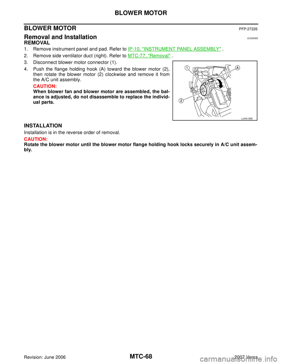
3. Disconnect blower motor connector (1).
4. Push the flange holding hook (A) toward the blower motor (2),
then rotate the blower motor (2) clockwise and remove it from
the A/C unit assembly.
CAUTION:
When blower fan and blower motor are assembled, the bal-
ance is adjusted, do not disassemble to replace the individ-
ual parts.
INSTALLATION
Installation is in the reverse order of removal.
CAUTION:
Rotate the blower motor until the blower motor flange holding hook locks securely in A/C unit assem-
bly.
LJIA0199E
Trending: tires, tire size, fuel consumption, ECO mode, window, boot, torque
